Makita 8391D Technical Information
Hide thumbs
Also See for 8391D:
- User manual ,
- Instruction manual (64 pages) ,
- Instruction manual (13 pages)
Advertisement
Quick Links
Download this manual
See also:
Instruction Manual
T
ECHNICAL INFORMATION
Models No.
Description
C
ONCEPT AND MAIN APPLICATIONS
Model 8391D has been developed as the successor model of 8390D,
featuring:
Single sleeve keyless drill chuck for easy bit installation/removal
New tool design
Model 8391D is available in the following variations.
Model No.
type
8391DZ
No
8391DWAE
1822
(Ni-Cd 2.0Ah)
8391DWALE
8391DWPE
PA18
(Ni-Cd 1.3Ah)
8391DWPLE
Also, the models include the accessory listed in "Standard equipment".
S
pecification
Voltage: V
Battery
Capacity: Ah
Cell
Max output: W
No load speed:
min-
=rpm
1
Impacts per minute:
min-
=ipm
1
Capacity of drill chuck: mm (")
Capacity: mm (")
Torque setting
Clutch torque setting: N.m (in.lbs)
Lock torque: N.m (in.lbs)
Max. fastening
torque: N.m (in.lbs)
Electric brake
Mechanical speed control
Variable speed control
Reverse switch
Net weight [with Battery 1822]: kg (lbs)
S
tandard equipment
+- Bit 2-65 (double-end) ........ 1 pc
Note: The standard equipment for the tool shown above may differ by country.
O
ptional accessories
Battery 1822
Battery 1835
Battery 1834
Battery 1835F
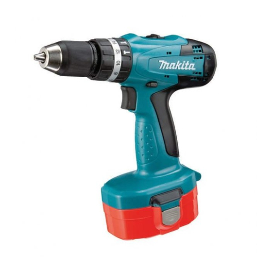
8391D
18V Cordless Hammer Driver Drill
13mm (1/2")
Battery
Battery
Charger
quantity
cover
---
No
No
2
2
DC1804
2
2
DC1804
High
Low
High
Low
Steel
Wood
Masonry
Hard joint
Soft joint
Battery PA18
Charger DC1804
Rechargeable
Plastic carrying
flashlight
case
No
No
No
Yes
ML180
No
Yes
ML180
18
1.3/ 2.0
Ni-Cd
230
0 - 1,300
0 - 400
0 - 19,500
0 - 6,000
1.5 - 13 (1/16 - 1/2)
13 (1/2)
36 (1-7/16)
13 (1/2)
16 stage + drill mode
1.0 - 4.0 (9 - 35)
38 (340)
42 (370)
27 (240)
Yes
Yes (2 speed)
Yes
Yes
2.3 (5.1)
Automotive charger DC1822
Drill bits for wood
L1
H
W
Dimensions: mm (")
Length (L1)/ (L2)
234 (9-1/4) / 241 (9-1/2)
Width (W)
Height (H)
L1: for all countries except those described
below in L2
L2: for countries of North America and
Latin America
Drill bits for steel
Drill bits for masonry
Driver bitsTCT drill bits
PRODUCT
P 1/ 7
L2
97 (3-13/16)
252 (9-7/8)
Advertisement

Related Manuals for Makita 8391D


Summary of Contents for Makita 8391D
- Page 1 8391D Description 18V Cordless Hammer Driver Drill 13mm (1/2") ONCEPT AND MAIN APPLICATIONS Model 8391D has been developed as the successor model of 8390D, featuring: Single sleeve keyless drill chuck for easy bit installation/removal New tool design Dimensions: mm (") Model 8391D is available in the following variations.
-
Page 2: Necessary Repairing Tools
Note: 1) Pay attention that the machine except Keyless drill chuck starts revolving with strong force. Do not pinch your hand between the moved machine and Vise in this step. 2) If it is impossible to remove Keyless drill chuck, use 1R359 (Chuck removing tool) to remove it. Refer to Makita repair tool list. - Page 3 P 3/ 7 epair [3] DISASSEMBLY/ASSEMBLY [3]-2. Gear Ass’y, DC Motor DISASSEMBLING (1) Remove Keyless drill chuck. (2) Gear ass’y and DC Motor can be disassembled in the order of Figs. 3, 4, 5, 6 and 7. Fig. 3 Fig. 4 Gear ass’y Housing set (R) 3x16 Tapping...
- Page 4 P 4/ 7 epair [3] DISASSEMBLY/ASSEMBLY [3]-2. Gear Assembly, DC Motor ASSEMBLING The following portions of DC motor, Motor bracket and Gear ass’y have to face the same side. (Fig. 8) * Red point mark (designated as plus terminal) on DC Motor * None of protrusion side of Motor bracket * Gear assembly’s protrusion Fig.
- Page 5 P 5/ 7 epair [3] DISASSEMBLY/ASSEMBLY [3]-4. Leaf Spring ASSEMBLING Before assembling Gear ass’y and DC motor, Leaf spring has to be mounted to Housing set (L) as illustrated in Fig. 12. Fig. 12 Housing set (L) Leaf spring Leaf spring [3]-5.
-
Page 6: Circuit Diagram
P 6/ 7 ircuit diagram Fig. D-1 Connecting of Lead Wire (red) Color index of lead wires' sheath to DC Motor Black red point mark Connect Lead wire (red) to the Terminal marked with red point mark. DC Motor Switch viewed from Switch viewed from Housing set (L) side Housing set (R) side... -
Page 7: Wiring Diagram
P 7/ 7 iring diagram Fig. D-2 Housing set (L) Rear view of Housing set (L) Red point mark DC Motor DC Motor has to be so assembled to Housing set (L) that its Red point mark Switchs’ Lead wires (black, red) have to be fixed with Lead wire is positioned on the back holder.