Advertisement
Available languages
Available languages
Quick Links
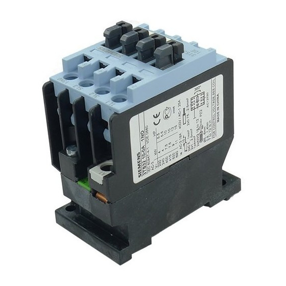
Contactor
Operating Instructions
Read and understand these instructions before installing,
operating, or maintaining the equipment.
DANGER
!
Hazardous voltage.
Will cause death or serious injury.
Turn off and lock out all power supplying this device before
working on this device.
CAUTION
Reliable functioning of the equipment is only ensured with
certified components.
Mounting
For dimension drawings (dimensions in mm) see:
Fig. Ia
Fig. Ib
Snap onto 35 mm standard mounting rail to DIN EN 50022 or fix on a plain surface
with two M4 screws. With screw mounting, always use plain washers and spring
washers. Cover the contactors during installation if foreign particles, such as swarf,
can fall onto them. Install contactors in a housing if they are exposed to dirt, dust or
aggressive atmospheres.
For permissible mounting positions see:
Fig. IIa
Fig. IIb
Connection
The terminal screws can be tightened with a power screwdriver.
Screwdriver blade width: 5 to 6 mm.
Permissible Conductor Cross-sections:
Solid
Finely stranded with end sleeve
AWG wires
Tightening Torque standard type
Tightening Torque auxiliary contact block
Use 75 °C copper wire only.
For circuit diagrams and positions of connection terminals see Fig. III。
- Fig. IIIa
- Fig. IIIb
- Fig. IIIc
Operation
Observe operating voltage (see rating plate of magnet coil).
The operating state of the contactor is shown at the position indicator; see Fig. IV.
.
When the system voltage is applied and the load is connected, do not
operate the contactor by pressing down the contact carrier.
Maintenance
The following components can be replaced:
magnet coil, single-pole auxiliary contact block 3TX3.
For Order No. see Catalog NSK.
Only use of original spare parts ensures the operational safety of contactors.
Cleaning
Remove dust by suction.
Auxiliary contact block
For replacement see Fig. V.
Magnet coil
For coil replacement see Fig. VI:
Fig. VIa
Fig. VIb
Ensure that the pole faces of the magnet coil are clean. Do not use grease solvents
or sharp objects for cleaning.
**Footnote: According to IEC 60947 / VDE 0660, the types of protection mean:
"Assignment type 1": Short circuits can cause damage to the contactors making replacement of the equipment necessary.
"Assignment type 2": Easily separable contact welding but no other damage.
A5E01070445A-02
Order No.: 3ZX3012-0TS30-0AY0
DIN VDE 0660, IEC 60947-4-1, Q/320500 SMS 009, GB14048.4
AC operation
DC operation
AC operation
DC operation
2
2 x 0.5 to 1 mm
2
2 x 1 to 2.5 mm
2
2 x 0.75 to 2.5 mm
2 x AWG 18 to 12
0.8 to 1.4 Nm
0.8 to 1.1 Nm
1NO
1NC
without auxiliary contacts
AC coil
DC coil
3TS29, 3TS30, 3TS31, 3TS32
Technical Data
Weight:
AC operation
DC operation
Permissible ambient temperature:
operation
storage
Main circuit
Rated insulation voltage U
i
Rated Insulation current I
/ AC-1 (55°C)
e
Rated operational voltage
3TS29
- 230 V
kW
1.5
- 240 V
kW
1.5
- 400 V
kW
2.2
- 415 V
kW
2.2
- 500 V
kW
3
- 690 V
kW
4
Short-circuit protection:
Degree of protection to DIN VDE
0660 / IEC 60947-4-1
- assinment type 1
- assignment type 2
- non-welding I
≥ 100 x I
k
e
- Circuit-breaker (C-char)
Auxiliary circuit
Rated operating voltage
- 230 V / 220 V
- 240 V
- 400 V / 380 V
- 415 V
- 500 V
- 690 V / 660 V
Rated operating voltage
- 24 V
- 48 V
- 110 V
- 220 V
- 440 V
- 600 V
Short-circuit protection:
Fuse-links NEOZED and DIAZED, gL (gG)
Circuit-breaker, C-char.
Auxiliary contact block 3TX3
Rated operating voltage
- 230 V
- 400 V
- 500 V
- 690 V
Rated operating voltage
- 24 V
- 48 V
- 110 V
- 220 V
- 440 V
- 600 V
Short-circuit protection:
Fuse-links NEOZED and DIAZED, gL (gG)
Circuit-breaker, C-char.
For further data and accessories see Catalog IC15.
English
approx. 370 g
approx. 580 g
-25 °C to +55 °C
-50 °C to +80 °C
AC 690 V
25 A
Motor rating P
/ AC-3
N
3TS30
3TS31
3TS32
2.4
3.3
2.6
3.6
4
5.5
4
5.5
5.5
7.5
5.5
7.5
Fuse-links Duty class gL (gG)
3TS29, 3TS30
3TS31, 3TS32
A
32
32
A
20
25
A
10
10
A
16
25
Rated operating current I
/ AC-15 / AC-11
e
A
10
A
10
A
6
A
4
A
4
A
2
Rated operating current I
/ DC-13 / DC-11
e
A
10
A
5
A
0.9
A
0.45
A
0.25
A
0.2
A
16
A
10
Rated operating currentI
/ AC-15 / AC-11
e
A
5.6
A
3.8
A
2.5
A
1.8
Rated operating currentI
/ DC-13 / DC-11
e
A
10
A
4.6
A
0.8
A
0.2
A
0.11
A
0.08
A
16
A
10
Last update: 01 April 2011
4
4
7.5
7.5
9
11
Advertisement

Related Manuals for Siemens 3TS30


Summary of Contents for Siemens 3TS30
- Page 1 3TS29, 3TS30, 3TS31, 3TS32 Contactor DIN VDE 0660, IEC 60947-4-1, Q/320500 SMS 009, GB14048.4 English Operating Instructions Read and understand these instructions before installing, Technical Data operating, or maintaining the equipment. Weight: AC operation approx. 370 g DANGER DC operation approx.
- Page 2 3TS29, 3TS30, 3TS31, 3TS32 Контактор DIN VDE 0660, IEC 60947-4-1, Q/320500 SMS 009, GB14048.4 Инструкция по эксплуатации Русский Перед установкой, вводом в эксплуатацию или Технические данные обслуживанием устройства необходимо прочесть и понять Масса: данную инструкцию. Управление АС прибл. 370 г...
- Page 3 3TS29, 3TS30, 3TS31, 3TS32 接触器 DIN VDE 0660, IEC 60947-4-1, Q/320500 SMS 009, GB14048.4 中文 使用说明 技术参数 安装、使用和维修本设备前必须先阅读并理解本说明。 重量 危险 - 交流操作 约 370 g - 直流操作 约 580 g 危险电压。 允许环境温度 可能导致生命危险或重伤危险。 - 工作时 -25 °C~+55 °C 操作设备时必须确保切断电源。 - 储存时...
- Page 4 M3,5 Ø4,8 Ø4,8 M3,5 M3,5 M3,5 M3,5 M3,5 mininum clearance from earthed parts 10 mm Минимальное расстояние до заземленных частей - 10 мм 中文 对接地部件的最小距离 10 mm 22,5º 22,5º 22,5º 22,5º 90º 90º IIIa 3TX3 001-2A 3TX3 010-2A 3TX4 001-4A 3TX4 010-4A 3ZX3012-0TS30-0AY0...
- Page 5 Technical Assistance: Telephone: +49 (0) 911-895-5900 (8°° - 17°° CET) SIEMENS AG Fax: +49 (0) 911-895-5907 Technical Assistance E-mail: technical-assistance@siemens.com Würzburger Str. 121 Internet: www.siemens.com/industrial-controls/technical-assistance D-90766 Fürth Subject to change without prior notice. Store for use at a later date. Order No.: 3ZX3012-0TS30-0AY0 © Siemens AG 2011...