Advertisement
Quick Links
Use
CE1N2874en
14.07.2005
Siemeca™ AMR
Network Node
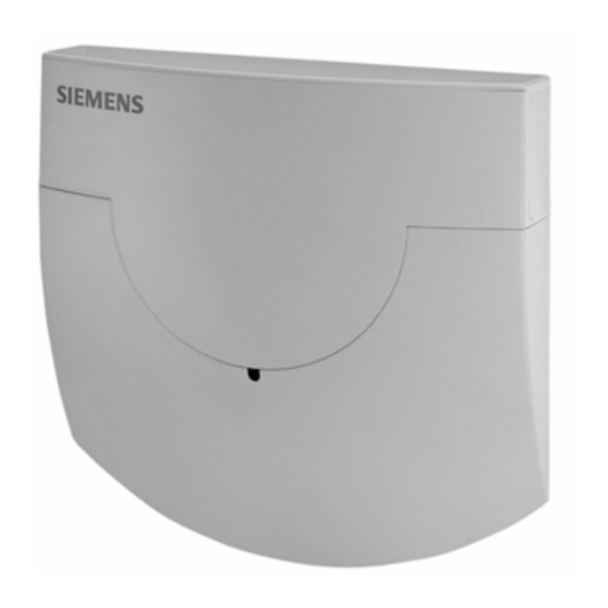
The WT...16... network node is used to receive and handle the data transmitted
by consumption meters of the Siemeca™ AMR system. In small plants, one net-
work node suffices as a data collector. In larger plants, or when consumption
data shall be read out from a remote location, an M-bus interface for connection
to an OZW10 M-bus central unit or a Siemeca™ gateway is required. The
WTT16... network node is battery-powered, the mains-powered WTX16... version
is available for special applications.
The WT...16... network node is a component of the Siemeca™ system. It has been
designed for use in buildings to create a radio network for receiving and storing the
data transmitted by the consumption meters installed in the building. Communication
between several network nodes is via radio also so that no wiring is required. All meas-
ured values acquired by the consumption meters are continuously exchanged within
the network, which means that every network node stores the current consumption
values, the values read out at the end of the month, and the set day values of all meter-
ing devices on the network. Owing to this operating principle, all network data can be
read out at any of the nodes, or a Siemeca™ gateway for remote data transmission can
be used with any of the nodes. The field of use of the Siemeca™ AMR system is de-
scribed in data sheet N2870.
2
WTT16...
WTX16...
Building Technologies
HVAC Products
874
Advertisement

Summary of Contents for Siemens WTT16 Series
- Page 1 Siemeca™ AMR WTT16… Network Node WTX16… The WT…16… network node is used to receive and handle the data transmitted by consumption meters of the Siemeca™ AMR system. In small plants, one net- work node suffices as a data collector. In larger plants, or when consumption data shall be read out from a remote location, an M-bus interface for connection to an OZW10 M-bus central unit or a Siemeca™...
- Page 2 Functions • Reception and storage of the data transmitted by the Siemeca™ AMR consumption meters • Automatic creation of a network with up to 12 WT…16 (with a maximum of 500 con- sumption meters) • Passing on all relevant consumption values to all WT…16 on the network •...
-
Page 3: Electronics Section
The housing with the electronics is identical for all types of network nodes. It contains Electronics section the network controls: MODE RESET DISPLAY Connector for M-bus service connection Connector for enhancements Screw terminal for the fixed M-bus connection Connector for power supply DC 3,6 V Connector for backup battery Indication of mains supply Operating mode button (red) Button for switching the display (blue) - Page 4 The display of the WT…16… facilitates commissioning work and troubleshooting. In Display addition to the standard display that shows the operating mode of the WTT16, there are 5 different display levels from “A“ to “E“ that can be selected by the user. Display level Current operating mode WT…16 number (primary address) and network...
- Page 5 State of the Display Explanation system Remote access When, from a PC, the WT…16 is accessed with a WTZ.RM radio module, symbol “ “ will appear High-speed For example When all WTT… have their receivers continu- mode ously on so that all new data can immediately be exchanged on the network, 2 dots will ap- pear in the upper half of the display Engineering notes...
- Page 6 closed insulating sleeves to ensure compliance with safety class II. Then, the live (L) and neutral (N) conductors must be connected to terminal “IN” of the power pack. Mains voltage must be in the range from AC 100 to 240 V (50 / 60 Hz). There is no protective earth (PE) connection.
- Page 7 as a confirmation. The result would be an erroneous display when showing the remain- ing capacity. First, remove the discharged main battery and insert the new one. Press the blue Battery replacement DISPLAY button once to start the life expectancy calculation for the new main battery. The backup battery MUST NOT be removed simultaneously.
- Page 8 Technical features are binding only when expressly agreed upon at the time a contract is concluded. ©2002 Siemens Building Technologies AG Subject to alteration Building Technologies Network Node WTT16…, WTX16…...


