JVC KW-AVX746 Installation & Connection Manual
Hide thumbs
Also See for KW-AVX746:
- Instructions manual (67 pages) ,
- Installation & connection manual (2 pages)
Advertisement
Quick Links
KW-AVX746/KW-AVX646
Installation/Connection Manual
LVT2177-002A
[U/UT]
ENGLISH
This unit is designed to operate on 12 V DC, NEGATIVE ground electrical systems. If your
vehicle does not have this system, a voltage inverter is required, which can be purchased at JVC
car audio dealers.
WARNINGS
• DO NOT install any unit or wire any cable in a location where;
– it may obstruct the steering wheel and gearshift lever operations, as this may result in a traffic
accident.
– it may obstruct the operation of safety devices such as air bags, as this may result in a fatal
accident.
– it may obstruct visibility.
• DO NOT operate any unit while manipulating the steering wheel, as this may result in a traffic
accident.
• The driver must not watch the monitor while driving. It may lead to carelessness and cause an
accident.
• If you need to operate the unit while driving, be sure to look around carefully or you may be
involved in a traffic accident.
• If the parking brake is not engaged, "Parking Brake" appears on the monitor, and no playback
picture will be shown.
– This warning appears only when the parking brake lead is connected to the parking brake
system built in the car.
To prevent short circuits, we recommend that you disconnect the battery's negative terminal and
make all electrical connections before installing the unit.
• Be sure to ground this unit to the car's chassis again after installation.
• Be sure any cable is not caught on the car's chassis or under seats.
Notes on electrical connections:
• Replace the fuse with one of the specified rating. If the fuse blows frequently, consult your JVC
car audio dealer.
• It is recommended to connect speakers with maximum power of more than 50 W (both at the
rear and at the front, with an impedance of 4 Ω to 8 Ω).
If the maximum power is less than 50 W, change <Amplifier Gain> setting to prevent the
speakers from being damaged (see page 38 of the INSTRUCTIONS).
• To prevent short circuits, cover the terminals of the
UNUSED leads with insulating tape.
• The heat sink becomes very hot after use. Be careful
not to touch it when removing this unit.
• At the time of installation, be sure to fix all wires
(wires both from this unit and from the car itself) in a
way that any wires cannot come into contact with heat
sinks on the rear and side of the unit.
PRECAUTIONS on power supply and speaker connections:
• DO NOT connect the speaker leads of the power cord to the car battery; otherwise,
the unit will be seriously damaged.
• BEFORE connecting the speaker leads of
the power cord to the speakers, check the
speaker wiring in your car.
Parts list for installation and connection
The following parts are provided for this unit.
If anything is missing, contact your dealer immediately.
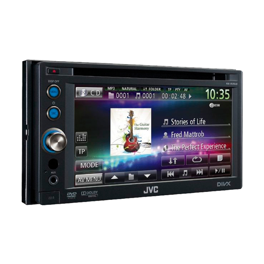
Main unit
Monitor panel and soft case
Extension lead
Power cord
Remove the metal protection plates from the unit before installation.
• Keep the round head screws (M5 x 8 mm) used to attach the metal protection plates. You
may need to use the screws for installation.
Only for KW-AVX746
Bluetooth adapter
Microphone
(inserted)
KS-UBT1
TROUBLESHOOTING
• The fuse blows.
* Are the red and black leads connected
correctly?
• Power cannot be turned on.
* Is the yellow lead connected?
• No sound from the speakers.
* Is the speaker output lead short-circuited?
• Sound is distorted.
* Is the speaker output lead grounded?
* Are the "–" terminals of L and R speakers
grounded in common?
Heat sink
Remote controller
RM-RK252
Batteries
Crimp connector
Flat head screws
Round head
(M5 x 8 mm)
screws
(M5 x 8 mm)
Bag for storing the adapter
• Noise interfere with sounds.
* Is the rear ground terminal connected to
the car's chassis using shorter and thicker
cords?
• This unit becomes hot.
* Is the speaker output lead grounded?
* Are the "–" terminals of L and R speakers
grounded in common?
• This unit does not work at all.
* Have you reset your unit?
INSTALLATION (IN-DASH MOUNTING)
The following illustration shows a typical installation. However, you should make adjustments corresponding to
your specific car. If you have any questions or require information regarding installation kits, consult your JVC
car audio dealer or a company supplying kits.
• If you are not sure how to install this unit correctly, have it installed by a qualified technician.
Before installing the unit
• When mounting the unit, be sure to use the screws provided, as instructed. If other screws are used, parts could
become loose or damaged.
• When tightening screws or bolts, be careful not to pinch any connection cord.
• Make sure not to block the fan on the rear to maintain proper ventilation when installing the unit.
1
Remove the audio system originally installed in the car, together with its mounting brackets.
• Be sure to keep all the screws and parts removed from your car for future use.
2
Attach the mounting brackets (removed from the car) to this unit (see below).
• Use flat head screws or round head screws, depending on installation location.
• When you need to use round head screws, use the supplied screws and the screws used to attach the metal
protection plates to the unit when shipped.
3
Do the required electrical connections.
• See "ELECTRICAL CONNECTIONS" on pages 1 and 2.
4
Install this unit using the screws removed in step
5
Attach the monitor panel (see below).
The following example is for installation in a Toyota car. For more details, consult your JVC car audio dealer.
Mounting bracket removed
from the car
Select the
appropriate type
fitting to your
audio system space.
Supplied screws
5
Step
Monitor panel
• When you use screws other than those
supplied, use 8 mm-long screws. If
longer screws are used, they could
damage the unit.
• Tighten the screws firmly to prevent
the unit from falling off.
ELECTRICAL CONNECTIONS
Connecting the parking brake lead
Parking brake
Crimp
connector
Parking brake switch
(inside the car)
Connecting the reverse gear signal lead (for rear view camera)
Locate the reverse lamp lead in the trunk.
Purple with
white stripe
1
© 2011 Victor Company of Japan, Limited
1
.
Screws removed from the car in step
When installing the unit in a Nissan car
If your Nissan car needs a plate, purchase the plate separately.
Plate for use with a
Nissan car (not supplied)
If necessary, restore the
Install the unit at an angle of
protruding tabs.
less than 30˚.
30˚
Extension lead
Extension lead (not supplied for this unit)
Crimp connector (not supplied
for this unit)
Reverse lamp lead
Reverse lamps
0111NYMMDWJEIN
EN, CT
Supplied
screws
1
Parking brake lead
(light green)
KW-AVX746
KW-AVX646
To metallic body or
chassis of the car
To reverse lamps
Advertisement

Related Manuals for JVC KW-AVX746


Summary of Contents for JVC KW-AVX746
- Page 1 The following example is for installation in a Toyota car. For more details, consult your JVC car audio dealer. • Be sure to ground this unit to the car’s chassis again after installation.
- Page 2 • Please contact your dealer to inquire about compatible navigation units. WHEEL REMOTE • JVC cannot guarantee proper operation of the external devices connected to the RGB input terminal. Steering wheel remote controller (equipped in the car) Connecting the external components...
- Page 3 • 參閱第 3 和 4 頁的“電路連接”。 • 確定沒有任何電纜纏繞在汽車底盤上或座位下方。 使用在步驟 拆卸的螺絲安裝本機。 進行電路連接時注意: 安裝顯示器面板(參閱下列內容)。 • 把保險絲更換為額定負荷值的保險絲。如果保險絲經常燒壞,請向 JVC 汽車音響分銷商 詢問。 • 後置和前置揚聲器的最大輸入功率應大於 50 W,其阻抗為 4 Ω – 8 Ω。 以下以豐田(Toyota)汽車安裝為例。請聯絡您的 JVC 汽車音響分銷商有關更多細節。 如果最大功率少於 50 W,請調校 <Amplifier Gain> 設定值,以防止揚聲器損壞(參閱使 用說明書的第 38 頁)。 • 為防止短路,請用絕緣帶包住未使用電線的端子。...
- Page 4 將外接導航裝置連接至 RGB 輸入端子。 外接導航 轉換器(另購)。關於詳情,請與銷售本機的汽車音響分銷商聯系。 觸摸屏上檢測到的方位訊息和導航裝置中的圖像 裝置 * 信號從該端子進行傳輸。 KW-AVX746 KW-AVX646 關於詳情,參閱外接導航裝置的使用手冊。 OE 遙控轉換器 * RGB 輸入端子 • 請洽詢分銷商關於相容導航裝置的訊息。 STEERING • JVC 不保證接上 RGB 輸入端子的外接裝置是否能正常操作。 WHEEL REMOTE 方向盤遙控器(汽車上配備) 連接外接裝置 KV-CM10 * 連接外接功率放大器和重低音揚聲器 後視照相機 CAMERA IN 您可以連接功率放大器以提昇尊車的音響系統。 • 將遙控導線(藍色帶有白色條紋)和其他裝置上的遙控導線連接起來,以便可以從本機進行 遙控。 • 將揚聲器和本機拔開,再接上功率放大器。將本機的揚聲器接線放置不用。...