Advertisement
Quick Links
I.
DESCRIPTION
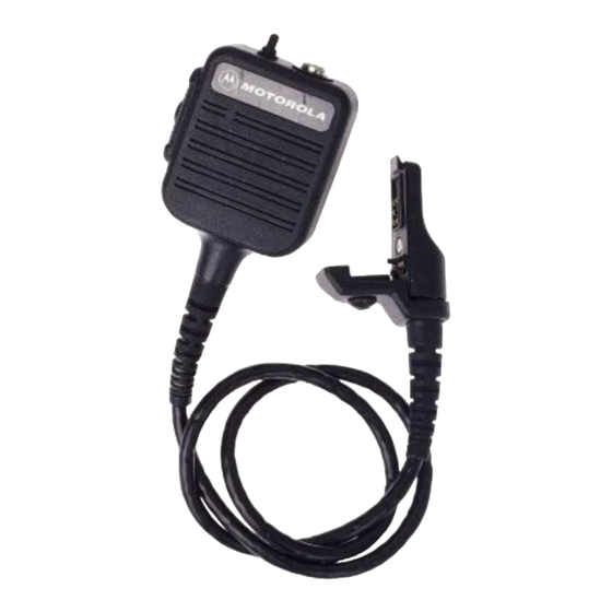
The NMN6227B, NMN6234B, and NMN6236B Public-
Safety Speaker/Microphones include a speaker, microphone,
push-to-talk (PTT) switch, high/low volume switch, swivel clip,
and cord connector assembly. The NMN6227B, NMN6234B,
and NMN6236B models are all the same, except that the
microphones' cord lengths are different: NMN6227B is 30",
NMN6234B is 24", and NMN6236B is 18". The public-safety
speaker/microphones also have a threaded antenna jack
located on top of the housing, which accepts any of the
following antennas:
TABLE 1. ANTENNAS
Antenna
Frequency
Kit Number
NAE6546
UHF, 403-435 MHz
NAE6547
UHF, 435-470 MHz
NAE6548
UHF, 470-512 MHz
NAF5042
800 MHz
•
The antenna is not supplied with the public safety
speaker/microphone kit, and it must be ordered
separately.
•
It is not recommended to use these public-safety
speaker/microphones with vhf radios, since radio
performance is reduced.
•
In shipping, a protective rubber seal (Motorola part
number
3205782P01)
microphone's antenna port. Use this seal to cover
the microphone or radio antenna port when not in
use.
When the speaker/microphone is attached to the radio,
the speaker in the radio is disabled, and the receiver audio is
connected to the accessory speaker. Similarly, the accessory
microphone is connected to the transmitter, and the
accessory PTT switch can now control the PTT function of
the radio. The radio microphone and PTT switch are still
operational, but since the radio speaker is disabled, you can
listen to the received audio only through the accessory
speaker.
II.
PERFORMANCE TEST
A. General
The speaker/microphone audio performance is designed
to be similar to that of the radio. The receive audio speaker
loudness, with the high/low switch on the microphone set for
, and Motorola are trademarks of Motorola, Inc.
© 1995 by Motorola, Inc.
Radio Products Group
8000 W. Sunrise Blvd., Ft. Lauderdale, FL 33322
Printed in U.S.A. 08/95. All Rights Reserved.
Description
Insulator
Color Code
3" Helical
3" Helical
3" Helical
Quarter Wave, Stubby
NOTES
is
inserted
in
the
SPEAKER/MICROPHONE
"high," will equal or exceed the loudness of the radio speaker.
The RF connector on the mike head is not wired as
coaxial. Transmit power measurements should read
ZERO at this connector.
The RF connector (J2) on the microphone head is wired
as center and shield shorted together and connected to the
RF coax cable center. The rf coax shield is connected to pcb
ground for best radiation performance.
B. Audio test
The speaker/microphone accessory can be checked for
proper performance by comparison with another new or
known good unit on the radio. Start each of the following two
tests with the new or known good unit on the radio.
RED
1.
Microphone - Transmit to a communications monitor
GREEN
while voicing a tone or the spoken word 'four.' The
BLACK
speaker/microphone should be held at a distance that
WHITE
causes approximately 3kHz deviation. Repeat these
conditions using the speaker/microphone to be tested.
Good units compare to each other within ±2kHz
deviation.
2.
Speaker - Using the communications monitor, generate
an rf signal to the radio. Set the modulation to a 1kHz
tone at 3kHz deviation. Set the high/low switch on the
speaker/microphone to "high." Set the volume control on
the radio to a loud, yet undistorted position. Without
disturbing any settings, repeat these conditions using the
speaker/microphone to be tested. Good units should
sound equally loud and undistorted. The "low" setting
loudness should compare as above.
C. Antenna test
Refer to Table 1 and verify that the proper antenna is
being used. Use one of the following to conduct this test:
•
a communications monitor set to spectrum analyzer is
best,
•
a monitor receiver set to threshold squelch, or
•
a field strength meter.
Connect a new or known good public-safety microphone
to the radio. Transmit to the equipment using the microphone
PTT by radiating to an input antenna on the equipment at a
distance that causes a mid-scale result. For a receiver set for
threshold squelch, set the squelch to just open when
transmitting. Connect the public-safety microphone for test to
the radio, and transmit at the same distance as above. The
result should compare closely to the known good or new
microphone for field intensity.
PUBLIC-SAFETY
Models: NMN6227B,
NMN6234B, and NMN6236B
NOTE
*6881083C60*
Service Manual
68P81083C60-A
Advertisement

Related Manuals for Motorola NMN6227B


Summary of Contents for Motorola NMN6227B
- Page 1 NMN6236B models are all the same, except that the The RF connector (J2) on the microphone head is wired microphones’ cord lengths are different: NMN6227B is 30”, as center and shield shorted together and connected to the NMN6234B is 24”, and NMN6236B is 18”. The public-safety RF coax cable center.
- Page 2 If disassembly of the public safety speaker microphone is required, do not reassemble it without doing the following Wearing a conductive wrist strap (Motorola No. RSX- (numbers in parentheses refer to item numbers in the 4015A) will minimize static buildup during servicing.
- Page 3 Electrical Parts List TPLF-4195-A REFERENCE MOTOROLA SYMBOL PART NO. DESCRIPTION CAPACITOR, Fixed: pF±5%; 63V SPEAKER: unless stated 5005213W01 1 3/4"; 28Ω 2113741B69 0.1µF 2184008H19 .022µF MICROPHONE: 5005227J06 Electret 2113740A53 2113740A67 RESISTOR, Fixed: Ω±5%; 1/8W C5, 6 Not Used unless stated...
- Page 4 - - - - - - - - - - CABLE and CONNECTOR; factory test 0105955P12 ASSEMBLY, Cover required, not field repairable 3305706X46 LABEL, Kit Number (NMN6227B) or 3305706X47 LABEL, Kit Number (NMN6234B) or 3305706X48 LABEL, Kit Number (NMN6236B) Note: Refer to Electrical Parts List for part number and description.