Advertisement
Quick Links
Thank you for purchasing a Sealey product. Manufactured to a high standard, this product will, if used according to these
instructions, and properly maintained, give you years of trouble free performance.
IMP
P
OR
R TA
TANT: PLEASE READ THESE INSTRUCTIONS CAREFULLY. NOTE THE SAFE OPERATIONAL REQUIREMENTS, WARNINGS & CAUTIONS. USE
TH
H E
P
P
RO
O DUCT CORRECTLY AND WITH CARE FOR THE PURPOSE FOR WHICH IT IS INTENDED. FAILURE TO DO SO MAY CAUSE DAMAGE AND/OR
PE
E
RS
S ON
N AL INJURY AND WILL INVALIDATE THE WARRANTY. KEEP THESE INSTRUCTIONS SAFE FOR FUTURE USE.
Refer to
Wear eye
instructions
protection
Electric shock
Electromagnetic
from welding
fi elds can cause
electrodes can
pacemaker
kill
malfunction
1. SAFETY
1.1.
ELECTRICAL SAFETY
WARNING! It is the user's responsibility to read, understand and comply with the following:
1.1.1.
You must check all electrical equipment and appliances to ensure they are safe before using. You must inspect power supply leads,
plugs and all electrical connections for wear and damage. You must ensure the risk of electric shock is minimised by the installation of
appropriate safety devices. An RCCB (Residual Current Circuit Breaker) should be incorporated in the main distribution board. We
also recommend that an RCD (Residual Current Device) is used with all electrical products. It is particularly important to use an RCD
together with portable products that are plugged into an electrical supply not protected by an RCCB. If in doubt consult a qualified
electrician. You may obtain a Residual Current Device by contacting your Sealey stockist. You must also read and understand the
following instructions concerning electrical safety.
1.1.2.
The Electricity At Work Act 1989 requires all portable electrical appliances, if used on business premises, to be tested by a qualified
electrician, using a Portable Appliance Tester (PAT), at regular intervals.
1.1.3.
The Health & Safety at Work Act 1974 makes owners of electrical appliances responsible for the safe condition of the appliance, and
the safety of the appliance operator. If in any doubt about electrical safety, contact a qualified electrician.
1.1.4.
Ensure the insulation on all cables and the product itself is safe before connecting to the mains power supply. See 1.1.1. & 1.1.2.
above and use a Portable Appliance Tester (PAT).
Ensure that cables are always protected against short circuit and overload.
1.1.5.
1.1.6.
Regularly inspect power supply leads, plugs and all electrical connections for wear and damage. Inspect power connections to
ensure that none is loose.
IMPORTANT: Ensure the voltage marked on the product is the same as the electrical power supply to be used and check that plugs
are fitted with the correct capacity fuse. A 13 amp plug may require a fuse smaller than 13 amps for certain products,
see fuse rating at right.
DO NOT pull or carry the powered appliance by its power supply lead.
DO NOT pull power plugs from sockets by the power cable.
DO NOT use worn or damaged leads, plugs or connections. Immediately replace or have repaired by a
qualified electrician. A U.K. 3 pin plug must be fitted according to the following instructions.
(UK only - see diagram at right).
Ensure the unit is correctly earthed via a three-pin plug.
a) Connect the green/yellow earth wire to the earth terminal.
b) Connect the brown live wire to live terminal.
c) Connect the blue neutral wire to the neutral terminal.
d) After wiring, check that there are no bare wires, that all wires have been correctly connected, that the
cable external insulation extends beyond the cable restraint and that the restraint is tight.
1.1.7.
Cable extension reels. When a cable extension reel is used it should be fully unwound before connection. A cable reel with an RCD
fitted is recommended since any product which is plugged into the cable reel will be protected. The section of the cable on the cable
reel is important and should be at least 1.5mm², but to be absolutely sure that the capacity of the cable is suitable for this product
and for others that may be used in the other output sockets, we recommend the use of 2.5mm² section cable.
© Jack Sealey Limited
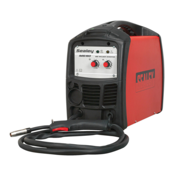
160A, 180A MIG/MMA WELDER INVERTER
MODEL NO:
Wear protective
Wear safety
gloves
footwear
Welding sparks
Arc rays can
can cause
burn eyes and
explosions or
Injure skin
fi re
Original Language Version
IMIG160.V2, IMIG180.V2
Wear protective
Wear a
clothing
welding helmet
Breathing
welding fumes
can be
hazardous to
your health
IMIG160.V2, IMIG180.V2 Issue 1 14/01/22
Keep away
Warning
from rain
Replacement
fuse rating: 13A
Advertisement

Related Manuals for Sealey IMIG160.V2


Summary of Contents for Sealey IMIG160.V2
- Page 1 160A, 180A MIG/MMA WELDER INVERTER IMIG160.V2, IMIG180.V2 MODEL NO: Thank you for purchasing a Sealey product. Manufactured to a high standard, this product will, if used according to these instructions, and properly maintained, give you years of trouble free performance. R TA TANT: PLEASE READ THESE INSTRUCTIONS CAREFULLY.
- Page 2 Use an air hose to regularly blow out any dirt from the liner and keep the welding set clean for best and safest performance. Check and spray the gas cup and contact tip regularly with anti-spatter spray, available from your Sealey stockist. ...
-
Page 3: Specification
3. SPECIFICATION Model ..................IMIG160.V2 ............IMIG180.V2 Welding Current: ................30 - 160A ............... 30 - 180A MIG: ........100% @ 72A , 60%, @ 92A, 20% @ 160A ..100% @ 80A , 60%, @ 104A, 20% @ 180A MMA: ........100% @ 58A , 60%, @ 75A, 20% @ 130A ... 100% @ 67A , 60%, @ 87A, 20% @ 150A Wire Capacity:.................. - Page 4 Set the wire speed control knob to position 5 or 6. Keep the torch cable as straight as possible and press the torch switch and the wire will feed through the torch. 5.6.12. When the wire has fully fed through, switch the welding set off and unplug from the mains. Original Language Version IMIG160.V2, IMIG180.V2 Issue 1 14/01/22 © Jack Sealey Limited...
- Page 5 With the exception of a metallic workbench DO NOT connect the return cable to any metallic structure which is not part of the workpiece, as this may be dangerous. 6. CONTROLS 6.1. Fig 13 illustrates the main panel control for IMIG160.V2. The panel control for IMIG180.V2 is identical. fi g.13 Original Language Version IMIG160.V2, IMIG180.V2 Issue 1 14/01/22...
-
Page 6: Maintenance
To keep the contact tip free from spatter, we recommend the use of Sealey anti-spatter spray (MIG/722307) available from your Sealey stockist.