Advertisement
Quick Links
BLOCK DIAGRAM
The differential input signal is converted to an optical signal by the Laser Diode Driver (LDD) and Laser Diode (LD) in the
plug.
The optical signal is transmitted through the optical fiber and reproduced as differential output signal by the Photo Diode
(PD) and Trans Impedance Amplifier (TIA).
Differential output
Differential input
Arrow.com.
Downloaded from
FEATURES
1. Plug connector is equipped with electrical/optical conversion function
(bi-direction, Max. 6 Gbps transmission).
2. High speed and wide data rate transmission possible: 20 Mbps to 6 Gbps
3. Integration is possible to a small apparatus with compact, bi-directional
transmission device.
4. Noise reduction and electrical isolation easily achieved.
APPLICATIONS
Recommended for the following high speed device transmission or electrical
isolation applications
• Measuring equipment
• Printer
• Industrial robots, etc.
TIA
LDD
LDD: Laser Diode Driver, LD: Laser Diode, TIA: Trans Impedance Amplifier, PD: Photo Diode
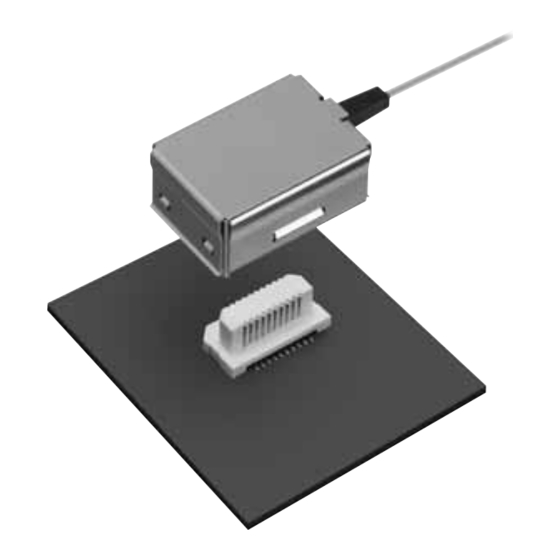
Vertical insertion type
Active Optical Connector
Optical fiber
Plug
(E/O conversion)
Electrical signal
(Differential signal)
Optical signal
Receptacle
LD
LD
Optical fiber
–1–
V
Electrical signal
(Differential signal)
• Image processing instrument
• Medical equipment
LDD
LD
Differential input
Differential output
PD
TIA
Series
[Transmitter]
<E/O Converter>
Laser diode
IC
[Receiver]
<O/E Converter>
Photo diode
IC
O/E: Optical/Electrical
conversion
E/O: Electrical/Optical
conversion
ACCTB69E 201602-T
Advertisement

Summary of Contents for Panasonic V Series
- Page 1 Vertical insertion type Series Active Optical Connector FEATURES 1. Plug connector is equipped with electrical/optical conversion function (bi-direction, Max. 6 Gbps transmission). [Transmitter] Optical fiber Plug <E/O Converter> (E/O conversion) Laser diode Electrical signal (Differential signal) [Receiver] Optical signal <O/E Converter> Photo diode Electrical signal Receptacle...
-
Page 2: Product Types
Active Optical Connector V Series PRODUCT TYPES 1. Integrated cable and plug Transmission rate Transmission specifications Cable length Part No. Packing quantity 50 mm AYG4V10565M1 300 mm AYG4V13065M1 10 pieces AYG4V1A065M1 20 Mbps to 6 Gbps Bi-direction, 1 channel 50 mm... -
Page 3: Terminal Layout
Active Optical Connector V Series 3. Materials specifications Component name Materials Specifications and Remarks Shell Copper alloy Nickel plating Bushing Elastomer Black Cross section: 0.4 × 0.6 mm, 2 cores Optical fiber Silica, UV-cured resin Connector LCP resin, copper alloy... - Page 4 Active Optical Connector V Series DIMENSIONS (Unit: mm) 1. Integrated cable and plug External dimensions 12.7 (3.9) General tolerance: ±0.3 L: Cable length Tolerance Part No. (mm) Unit AYG4V10565 −0 AYG4V13065 −0 +100 AYG4V1A065 −0 2. Receptacle External dimensions 0.10 0.50±0.05...
- Page 5 Active Optical Connector V Series EMBOSSED TAPE DIMENSIONS (Unit: mm) Receptacle: Embossed tape packaging • Specifications for taping (In accordance with JIS C 0806:1990. • Specifications for the plastic reel (In accordance with EIAJ ET- However, not applied to the mounting-hole pitch of some 7200B.)
- Page 6 Notes on Using Active Optical Connector V Series Notes on Using Active Optical Connector V Series ■ About safety Remarks 6) Insertion and removal operations must be performed while the 1) Do not use these connectors beyond the specification sheets.
- Page 7 Notes on Using Active Optical Connector V Series ■ Receptacle Recommended PC board pattern (TOP VIEW) Recommended metal mask pattern Recommended metal mask pattern Metal mask thickness: When 150μm Metal mask thickness: When 120μm (Opening ratio: 69%) (Opening ratio: 87%) 0.50±0.05...
- Page 8 Notes on Using Active Optical Connector V Series Handling Single Components (for Receptacle) 1) Make sure not to drop or allow parts to 3) Do not insert or remove the connector fall from work bench. when it is not soldered. Forcibly applied...


