Advertisement
Quick Links
Connecting the Valve Wires (Figure 3)
Step 1- Route a multi-wire, direct-burial sprinkler
cable from the sprinkler timer to the valves. If the
cable run is less than 800', 18 AWG wire is suffi-
cient. For distance from 800' – 2000', 14 AWG wire
is recommended.
Step 2- Using wire splice connectors, attach either
wire from each valve solenoid to the white cable
wire. This wire is designated as the valve "Common
Wire." Connect the remaining wire from the sole-
noid to one of the color-coded wires.
Important: All wire splices must be properly insu-
lated to prevent a short circuit or corrosion
from occurring. Installing grease caps or waterproof
connectors is recommended.
Step 3- At the timer, connect the control wires from
valves to the numbered terminals in the desired
operating sequence. Connect the valve common
wire to the valve common terminal.
Step 4- Using the timer's manual control feature,
test the operation of each valve.
Finishing the Installation (Figure 4)
Step 1- Once valve operation has been successfully
tested with the timer, control wires can be buried
and a valve box installed.
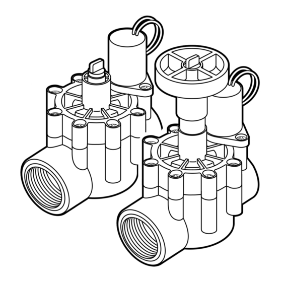
Manual Operation (Figure 5)
• Manually open the valve by turning the bleed
screw counterclockwise 1/2 turn. To close the valve,
turn the bleed screw clockwise. Do not over-tighten!
Note: The valve may take several seconds to shut off when operated manually.
• To adjust flow, (model 53682 only) turn the flow control handle clockwise to
decrease or counterclockwise to increase flow.
The Toro Promise — Limited One-Year Warranty
The Toro Company and its affiliate, Toro Warranty Company, pursuant to an agreement between them, jointly warrants, to the
owner, each new piece of equipment against defects in material and workmanship for the period of one year from the date of purchase.
Neither Toro nor Toro Warranty Company is liable for failure of products not manufactured by them even though such products
may be sold or used in conjunction with Toro products.
During such warranty period, we will repair or replace, at our option, any part found to be defective.
Return the defective part to the place of purchase.
Our liability is limited solely to the replacement or repair of defective parts. There are no other express warranties.
This warranty does not apply where equipment is used, or installation is performed, in any manner contrary to Toro's specifications
and instructions, nor where equipment is altered or modified.
Neither Toro nor Toro Warranty Company is liable for indirect, incidental or consequential damages in connection with the
use of equipment, including but not limited to: vegetation loss, the cost of substitute equipment or services required during peri-
ods of malfunction or resulting non-use, property damage or personal injury resulting from installer's negligence.
Some states do not allow the exclusion or limitation of incidental or consequential damages, so the above limitation or exclusion
may not apply to you.
All implied warranties, including those of merchantability and fitness for use, are limited to the duration of this express warranty.
Some states do not allow limitations of how long an implied warranty lasts, so the above limitation may not apply to you.
This warranty gives you specific legal rights and you may have other rights which vary from state to state.
© 2001 The Toro Company, Irrigation Division
Grease Cap
Figure 3
Timer Connection
Common
Wire
Figure 4
Figure 5
Bleed Screw
Flow Control
Handle
Form Number 373-0158 Rev. B
1" In-line Valve Models 53682 and 53683
Installation Guide
-
The Toro 1" in-line electric valves are designed
for use in an automatic sprinkler system controlled
by a 24 V a.c. timer. Both valve models feature
1" female-threaded inlet and outlet and manual
bleed control which enables the valve to be
operated without the use of the timer. In addi-
tion, the 53682 valve model features manual
flow control adjustable to zero flow.
The in-line valve is generally installed below
grade, grouped with other valves in a manifold
arrangement and housed in a protective valve box.
Important: A backflow prevention device installed between
the 1" in-line valve(s) and the water source point of connection is required in most
areas to prevent back-siphoning of contaminants through the sprinkler system into the
potable water supply. The Toro 1" Pressure Vacuum Breaker (PVB), model number
53300, is specifically designed for this purpose. Before connecting your irrigation system
to the potable water supply, consult with your local water utility department for infor-
mation regarding the type of backflow prevention device required for safe operation.
Valve Specifications:
Operating Pressure: 20–150 PSI
Flow Range: 5–45 GPM
Manual Flow Control: Adjustable to Zero Flow
Solenoid:
24 V a.c., 60 Hz (nominal)
19 V a.c., 60 Hz (minimum)
Inrush: 0.30 amps, 7.2 VA @ 24 V a.c., 60 Hz
Holding: 0.20 amps, 4.8 VA @ 24 V a.c., 60 Hz
Friction Loss:
GPM Flow
5
10
15
20
PSI Loss
3.5
4.0
3.0
3.3
Installation Procedure
Note: To ensure ease of installation and optimum valve performance, please read
through the following instructions completely before starting the installation procedure.
Step 1- Route 1" schedule 40 PVC pipe from the backflow preventer or system shut-
off device to the valve location. Flush the supply line thoroughly!
Caution: Dirt, rocks and debris entering the valve can damage the valve and/or
cause the valve to malfunction.
Step 2- The diagrams on the next page illustrate the two most commonly recom-
mended methods of installing valves in a manifold arrangement. Referring to instal-
lation Method A or B, follow one of the installation procedures.
-
53683
30
35
40
45
6.2
7.0
8.7
10.5
53682
Advertisement

Related Manuals for Toro 53682


Summary of Contents for Toro 53682
- Page 1 Neither Toro nor Toro Warranty Company is liable for failure of products not manufactured by them even though such products Note: To ensure ease of installation and optimum valve performance, please read may be sold or used in conjunction with Toro products.
- Page 2 Installation Method A (Figure 1) • Figure 1 - Installation Method A Step 1- Apply three complete wraps of Teflon tape to the slip/thread adapters. ® Caution: Use only Teflon tape on threaded connections. Pipe dope and other types of pipe thread sealants can damage plastic threads. Valve Inlet Step 2- Install a slip/thread adapter into each end of the valve and tighten securely.