Asus P4S800-MX User Manual
Asus computer hardware user manual
Hide thumbs
Also See for P4S800-MX:
- User manual (84 pages) ,
- Manuel (64 pages) ,
- Guide utilisateur (88 pages)
Table of Contents
Advertisement
Advertisement
Table of Contents

Related Manuals for Asus P4S800-MX


Summary of Contents for Asus P4S800-MX
- Page 1 P4S800-MX (Maxdata) User Guide...
- Page 2 Product warranty or service will not be extended if: (1) the product is repaired, modified or altered, unless such repair, modification of alteration is authorized in writing by ASUS; or (2) the serial number of the product is defaced or missing.
-
Page 3: Table Of Contents
Creating a bootable floppy disk ... 2-2 2.1.2 Using AFUDOS to copy the current BIOS ... 2-3 2.1.3 Using AFUDOS to update the BIOS ... 2-3 2.1.4 Using ASUS EZ Flash to update the BIOS ... 2-5 2.1.5 Recovering the BIOS with CrashFree BIOS ... 2-6... - Page 4 Exit menu ... 2-28 Chapter 3: Software support Install an operating system ... 3-2 Support CD information ... 3-2 3.2.1 Running the support CD ... 3-2 3.2.2 Drivers menu ... 3-3 3.2.3 Utilities menu ... 3-3 3.2.4 ASUS contact information ... 3-4...
-
Page 5: Notices
Notices Federal Communications Commission Statement This device complies with FCC Rules Part 15. Operation is subject to the following two conditions: • This device may not cause harmful interference, and • This device must accept any interference received including interference that may cause undesired operation. -
Page 6: Safety Information
Safety information Electrical safety • To prevent electrical shock hazard, disconnect the power cable from the electrical outlet before relocating the system. • When adding or removing devices to or from the system, ensure that the power cables for the devices are unplugged before the signal cables are connected. -
Page 7: P4S800-Mx Specification Summary
P4S800-MX specifications summary Socket 478 for Intel Intel New power design for next generation Intel Chipset SiS661 FX SiS963L Front Side Bus (FSB) 800/533/400 MHz Memory 2 x 184-pin DDR DIMM sockets for up to 2GB memory Supports PC3200/2700/2100 unbuffered non-ECC DDR DIMMs. -
Page 8: About This Guide
NOTE: Tips and additional information to aid in completing a task. viii 4Mb Flash EEPROM, DMI, PnP features, SM BIOS 2.3, WfM 2.0, ASUS CrashFree BIOS, ASUS EZ Flash, and ASUS C.P.U. (CPU Parameter Recall) PCI 2.2, USB 2.0/1.1 WOL/WOR by PME, Wake on USB KB/Mouse Micro-ATX form factor: 9.6 in x 9.6 in (24.5 cm x 24.5 cm) - Page 9 Chapter 1 This chapter describes the features of the motherboard. It includes brief descriptions of the motherboard components, and illustrations of the layout, jumper settings, and connectors. Product introduction...
-
Page 10: Welcome
Welcome! Thank you for buying the ASUS The ASUS P4S800-MX motherboard delivers a host of new features and latest technologies making it another standout in the long line of ASUS quality motherboards! Before you start installing the motherboard, and hardware devices on it, check the items in your package with the list below. - Page 11 DLS2 MIDI synthesizer with Yamaha DLSbyXG sound set, 5.1 Virtual Theater™ and supports all major game audio technologies including Microsoft DirectX™8.0, Microsoft DirectSound 3D™, A3D, MacroFX, ZoomFX, MultiDrive 5.1 and EAX. See page 1-17. ASUS P4S800-MX motherboard user guide...
-
Page 12: Asus Crashfree Bios
USB 2.0 connectivity The P4S800-MX rear panel is equipped with four (4) Universal Serial Bus (USB) ports to connect USB 2.0 devices. A USB header is also available at mid-board to accommodate a USB module for two (2) additional USB ports. The USB ports and header comply with USB 2.0 specification that supports up to 480 Mbps connection... -
Page 13: Before You Proceed
Onboard LED The P4S800-MX comes with a stand-by power LED. When lit, the green LED indicates that the system is ON, in sleep mode, or in soft-off mode, a reminder that you should shut down the system and unplug the power cable before removing or plugging in any motherboard component. -
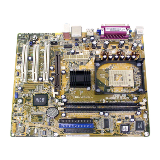
Page 14: Motherboard Overview
Motherboard overview 1.5.1 Motherboard layout KBPWR1 PS/2KBMS T: Mouse B: Keyboard COM1 VGA1 USB1 USB2 ATX12V1 USB2.0 Top: T: USB3 RJ-45 B: USB4 Top:Line In Center:Line Out Below:Mic In Accelerated Graphics Port (AGP1) AUX1 AD1888 CODEC FP_AUDIO1 SB_PWR1 SPDIF COM2 KBPWR1 USBPW12 USBPW34... -
Page 15: Placement Direction
Place eight (8) screws into the holes indicated by circles to secure the motherboard to the chassis. Do not overtighten the screws! Doing so may damage the motherboard. Place this side towards the rear of the chassis ASUS P4S800-MX motherboard user guide... -
Page 16: Central Processing Unit (Cpu)
4 processor has a gold triangular mark on one corner. This mark indicates the processor Pin 1 that should match a specific corner of the CPU socket. P4S800-MX Socket 478 Incorrect installation of the CPU into the socket may bend the pins and severely damage the CPU! ®... -
Page 17: Installing The Cpu
6. Install a CPU heatsink and fan following the instructions that came with the heatsink package. 7. Connect the CPU fan cable to the CPU_FAN1 connector on the motherboard. ASUS P4S800-MX motherboard user guide Socket Lever Gold Mark 90 - 100... -
Page 18: System Memory
You may install 64MB, 128MB, 256MB, 512MB, and 1GB DDR DIMMs into the DIMM sockets. Obtain DDR DIMMs only from ASUS qualified vendors. Refer to the Qualified DDR400 vendors list next page. Visit the ASUS website (www.asus.com) for the latest DDR Qualified Vendors List. -
Page 19: Installing A Dimm
A DDR DIMM is keyed with a notch so that it fits in only one direction. DO NOT force a DIMM into a socket to avoid damaging the DIMM. ASUS P4S800-MX motherboard user guide Part Number Chip Brand Side/s*... -
Page 20: Expansion Slots
Expansion slots In the future, you may need to install expansion cards. The following sub-sections describe the slots and the expansion cards that they support. Make sure to unplug the power cord before adding or removing expansion cards. Failure to do so may cause you physical injury and damage motherboard components. -
Page 21: Standard Interrupt Assignments
When using PCI cards on shared slots, ensure that the drivers support “Share IRQ” or that the cards do not need IRQ assignments. Otherwise, conflicts will arise between the two PCI groups, making the system unstable and the card inoperable. ASUS P4S800-MX motherboard user guide Standard Function System Timer Keyboard Controller... -
Page 22: Pci Slots
Note the notches on the card golden fingers to ensure that they fit the AGP slot on the motherboard. This motherboard does not support 3.3V AGP cards. Install only +1.5V AGP cards. P4S800-MX Accelerated Graphics Port (AGP) 1-14 Keyed for 1.5v Chapter 1: Product introduction... -
Page 23: Jumpers
4. Hold down the <Del> key during the boot process and enter BIOS setup to re-enter data. Except when clearing the RTC RAM, never remove the cap on CLRTC1 jumper default position. Removing the cap will cause system boot failure! P4S800-MX Clear RTC RAM ASUS P4S800-MX motherboard user guide CLRTC1 Normal Clear CMOS (Default) - Page 24 2. The total current consumed must NOT exceed the power supply capability (+5VSB) whether under normal condition or in sleep mode. P4S800-MX USB Device Wake Up 3. Keyboard power (3-pin KBPWR1) This jumper allows you to enable or disable the keyboard wake-up feature. Set this jumper to pins 2-3 (+5VSB) if you wish to wake up the computer when you press a key on the keyboard (the default is the Space Bar).
-
Page 25: Connectors
9. VGA port. This port connects a VGA compatible monitor. 10. Serial port. This 9-pin COM port is for pointing devices or other serial devices. 11. PS/2 keyboard port. This purple connector is for a PS/2 keyboard. ASUS P4S800-MX motherboard user guide 4-Speaker Line In... -
Page 26: Internal Connectors
(Pin 5 is removed to prevent incorrect insertion when using ribbon cables with pin 5 plug). P4S800-MX Floppy Disk Drive Connector 1-18 NOTE: Orient the red markings (usually zigzag) on the IDE ribbon cable to PIN 1. - Page 27 Be default, the pins labeled LINE OUT_R/BLINE_OUT_R and the pins LINE OUT_L/BLINE_OUT_L are shorted with jumper caps. Remove the caps only when you are connecting the front panel audio cable. P4S800-MX Front Panel Audio Connector ASUS P4S800-MX motherboard user guide ATX12V1...
- Page 28 These are not jumpers! DO NOT place jumper caps on the fan connectors! P4S800-MX 12-Volt Fan Connectors 6. USB header (10-1 pin USB56) If the USB ports on the rear panel are inadequate, a USB header is available for two (2) additional USB ports.
- Page 29 LED cable from the system chassis to this connector. The LED lights up when you turn on the system power, and blinks when the system is in sleep mode. P4S800-MX PLED Setting ASUS P4S800-MX motherboard user guide AUX1 (White) CD1 (Black)
- Page 30 An S/PDIF Out connector is available for an S/PDIF audio module. Connect one end of the S/PDIF audio module cable to this connector and the other end to the S/PDIF module. P4S800-MX Digital Audio Connector The S/PDIF module is purchased separately. 11. GAME/MIDI connector (16-1 pin GAME1) This connector supports a GAME/MIDI module.
- Page 31 By default, the pins labeled “Chassis Signal” and “Ground” are shorted with a jumper cap. If you wish to use the chassis intrusion detection feature, remove the jumper cap from the pins. P4S800-MX Chassis Alarm Lead ASUS P4S800-MX motherboard user guide COM2 PIN 1 CHASSIS1...
- Page 32 14. System panel connector (10-1 pin F_PANEL1) This connector accommodates several system front panel functions. P4S800-MX Front Panel Audio Connector • Power LED Lead (2-pin PWR_LED) This 2-pin connector connects to the system power LED. The LED lights up when you turn on the system power, and blinks when the system is in sleep mode.
- Page 33 Chapter 2 This chapter tells how to change system settings through the BIOS Setup menus. Detailed descriptions of the BIOS parameters are also provided. BIOS information...
-
Page 34: Managing And Updating Your Bios
BIOS file to a bootable floppy disk in case you need to restore the BIOS in the future. Copy the original motherboard BIOS using the AFUDOS utility. • Visit the ASUS website to download the latest BIOS file for this motherboard. 2.1.1 Creating a bootable floppy disk 1. -
Page 35: Using Afudos To Copy The Current Bios
To update the BIOS using the AFUDOS.EXE: 1. Visit the ASUS website (www.asus.com) to download the latest BIOS file for your motherboard. Save the BIOS file to a bootable floppy disk. ASUS P4S800-MX motherboard user guide... - Page 36 Write down the BIOS file name to a piece of paper. You need to type the exact BIOS file name at the prompt. 2. Copy the AFUDOS.EXE utility from the support CD to the bootable floppy disk that contains the BIOS file. 3.
-
Page 37: Using Asus Ez Flash To Update The Bios
2.1.4 Using ASUS EZ Flash to update the BIOS The ASUS EZ Flash feature allows you to easily update the BIOS without having to go through the long process of booting from a floppy disk and using a DOS-based utility. The EZ Flash is built-in the BIOS LPC chip so it is accessible by simply pressing <Alt>... -
Page 38: Recovering The Bios With Crashfree Bios
To use the CrashFree BIOS feature on this motherboard, install a VGA card in one of the expansion slots before rebooting the computer. On motherboards with onboard VGA, such as the P4S800-MX, you will not see the screen display when the BIOS crashes even if you reboot the computer. - Page 39 4. When the BIOS update process is complete, reboot the system. The recovered BIOS may not be the latest BIOS version for this motherboard. Visit the ASUS website (www.asus.com) to download the latest BIOS file. ASUS P4S800-MX motherboard user guide...
-
Page 40: Bios Setup Program
The BIOS setup screens shown in this chapter are for reference purposes only, and may not exactly match what you see on your screen. • Visit the ASUS website (www.asus.com) to download the latest product and BIOS information. Chapter 2: BIOS information... -
Page 41: Bios Menu Screen
At the bottom right corner of a menu screen are the navigation keys for that particular menu. Use the navigation keys to select items in the menu and change the settings. Some of the navigation keys differ from one screen to another. ASUS P4S800-MX motherboard user guide Configuration fields [11:51:19] Use [ENTER], [TAB]... -
Page 42: Menu Items
Language [English] Use [+] or [-] to Primary IDE Master :[ST320413A] configure system time. Primary IDE Slave :[ASUS CD-S340] Secondary IDE Master :[Not Detected] Secondary IDE Slave :[Not Detected] System Information Select Screen Select Item Change Field... -
Page 43: Main Menu
2.3.3 Legacy Diskette A [1.44M, 3.5 in.] Sets the type of floppy drive installed. Configuration options: [Disabled] [360K, 5.25 in.] [1.2M , 5.25 in.] [720K , 3.5 in.] [1.44M, 3.5 in.] [2.88M, 3.5 in.] ASUS P4S800-MX motherboard user guide [01:29:59] Use [ENTER], [TAB]... -
Page 44: Primary And Secondary Ide Master/Slave
2.3.4 Primary and Secondary IDE Master/Slave While entering Setup, BIOS auto-detects the presence of IDE devices. There is a separate sub-menu for each IDE device. Select a device item then press <Enter> to display the IDE device information. Primary IDE Master Device : Hard Disk Vendor... -
Page 45: System Information
: Genuine Intel(R) CPU 3.20GHz Speed : 2800MHz Count System Memory Size : 224MB AMI BIOS Displays the auto-detected BIOS information. Processor Displays the auto-detected CPU specification. System Memory Displays the auto-detected system memory. ASUS P4S800-MX motherboard user guide 2-13... -
Page 46: Jumperfree Configuration
Advanced menu The Advanced menu items allow you to change the settings for the CPU and other system devices. Take caution when changing the settings of the Advanced menu items. Incorrect field values may cause the system to malfunction. JumperFree Configuration CPU Configuration Chipset Onboard Devices Configuration... -
Page 47: Cpu Configuration
Technology. Configuration options: [Enabled] [Disabled] The Hyper-Threading Technology item appears only when you install an Intel ® Pentium 4 CPU with Hyper-Threading Technology support. ASUS P4S800-MX motherboard user guide Sets the ratio between CPU Core Clock and the FSB Frequency. NOTE: If an invalid... -
Page 48: Chipset
2.4.3 Chipset The Chipset menu items allow you to change the advanced chipset settings. Select an item then press <Enter> to display the sub-menu. NorthBridge SIS661FX Configuration SouthBridge SiS963/SiS963L Configuration NorthBridge SIS661FX Configuration Primary Graphics Adapter MA 1T/2T Latency DRAM CAS# Latency DRAM Precharge Delay DRAM RAS# to CAS# Delay DRAM RAS# Precharge... - Page 49 Allows you to enable or disable the optional ROM in the onboard LAN controller. This item appears only when the Onboard SiS900 LAN DEVICE item is set to Enabled. Configuration options: [Disabled] [Enabled] ASUS P4S800-MX motherboard user guide [Enabled] <Enter> to enable or [Enabled] disable.
-
Page 50: Onboard Devices Configuration
2.4.4 Onboard Devices Configuration Serial Port1 Address Serial Port2 Address Parallel Port Address Parallel Port Mode Parallel Port IRQ OnBoard Game Port OnBoard MIDI POrt Serial Port1 Address [3F8/IRQ4] Allows you to select the Serial Port1 base address. Configuration options: [Disabled] [3F8/IRQ4] [3E8/IRQ4] [2E8/IRQ3] Serial Port2 Address [2F8/IRQ3] Allows you to select the Serial Port2 base address. -
Page 51: Pci Pnp
Setting to [Disabled] deactivates this feature. Configuration options: [Disabled] [Enabled] PCI IDE BusMaster [Enabled] Allows BIOS to use PCI bus mastering when reading/writing to IDE devices. Configuration options: [Disabled] [Enabled] ASUS P4S800-MX motherboard user guide [No] [64] [Yes] [Disabled]... -
Page 52: Usb Configuration
IRQ-xx assigned to [PCI Device] When set to [PCI Device], the specific IRQ is free for use of PCI/PnP devices. When set to [Reserved], the IRQ is reserved for legacy ISA devices. Configuration options: [PCI Device] [Reserved] 2.4.5 USB Configuration The items in this menu allows you to change the USB-related features. -
Page 53: Power Menu
Allows you to enable or disable the ACPI support in the ASIC. When set to Enabled, the ACPI APIC table pointer is included in the RSDT pointer list. Configuration options: [Disabled] [Enabled] ASUS P4S800-MX motherboard user guide [Yes] [Auto] [No]... -
Page 54: Apm Configuration
2.5.5 APM Configuration Restore On AC Power Loss Power On by PS2 Keyboard Power On by PS2 MOUSE Power On by Internal MAC LAN Power On by PCI Devices Power On by External Modems Power On by RTC Alarm Restore on AC Power Loss [Always OFF] When set to Always OFF, the system goes into off state after an AC power loss. -
Page 55: Hardware Monitor
Configuration options: [Ignored] [xxxRPM] Q-Fan Control [Enabled] Allows you to enable or disable the ASUS Q-Fan feature that smartly adjusts the fan speeds for more efficient system operation. When this field is set to [Enabled], the Q-Fan Control Temperature and Q-Fan Control Tolerance items appear. -
Page 56: Boot Device Priority
These items specify the boot device priority sequence from the available devices. The number of device items that appear on the screen depends on the the number of devices installed in the system. Configuration options: [xxxxx Drive] [Disabled] 2-24 [1st FLOPPY DRIV] [PM-ST320413A] [PS-ASUS CD-S340] Chapter 2: BIOS information... -
Page 57: Boot Settings Configuration
This allows you to enable or disable the full screen logo display feature. Configuration options: [Disabled] [Enabled] Make sure that the above item is set to [Enabled] if you wish to use the ASUS MyLogo™ feature. AddOn ROM Display Mode [Force BIOS] Sets the display mode for option ROM. -
Page 58: Security
2.6.3 Security The Security menu items allow you to change the system security settings. Select an item then press <Enter> to display the configuration options. Security Settings Supervisor Password User Password Change Supervisor Password Change User Password Clear User Password Change Supervisor Password Select this item to set or change the supervisor password. -
Page 59: Change User Password
To change the user password, follow the same steps as in setting a user password. Clear User Password Select this item if you want to clear the user password. ASUS P4S800-MX motherboard user guide : Installed : Not Installed [Full Access]... -
Page 60: Exit Menu
Exit menu The Exit menu items allow you to load the optimal or failsafe default values for the BIOS items, and save or discard your changes to the BIOS items. Exit Options Exit & Save Changes Exit & Discard Changes Discard Changes Load Setup Defaults Pressing <Esc>... - Page 61 Chapter 3 This chapter describes the contents of the support CD that comes with the motherboard package. Software support...
-
Page 62: Install An Operating System
The contents of the support CD are subject to change at any time without notice. Visit the ASUS website for updates. 3.2.1 Running the support CD To begin using the support CD, simply insert the CD into your CD-ROM drive. The CD automatically displays the Drivers menu if Autorun is enabled in your computer. -
Page 63: Drivers Menu
ASUS PC Probe This smart utility monitors the fan speed, CPU temperature, and system voltages, and alerts you on any detected problems. This utility helps you keep your computer at a healthy operating condition. ASUS P4S800-MX motherboard user guide... -
Page 64: Asus Contact Information
Install ASUS Update This program allows you to download the latest version of the BIOS from the ASUS website. Before using the ASUS Update, make sure that you have an Internet connection so you can connect to the ASUS website. See page 2-7 for ASUS Update installation and use.