Table of Contents
Advertisement
Advertisement
Table of Contents

Related Manuals for Motorola AP6522


Summary of Contents for Motorola AP6522
- Page 1 AP6522 Access Point INSTALLATION GUIDE...
- Page 2 AP6522 Access Point MOTOROLA SOLUTIONS and the Stylized M Logo are registered in the US Patent & Trademark Office. © Motorola Solutions, Inc. 2012. All rights reserved.
-
Page 3: Table Of Contents
2.8 External Antenna Suspended Ceiling Tile (Plenum) Mount ....17 2.9 AP6522 External Antenna Model Antenna Options ......18 2.10 LED Indicators . -
Page 4: Introduction
The AP6522 access point provides multiple deployment options. The AP6522 access point receives all power and transfers data through the same CAT-5 or better Ethernet cable. An 802.3af Ethernet switch or power supply (specifically rated for the AP6522) is required (Part No. -
Page 5: Warnings
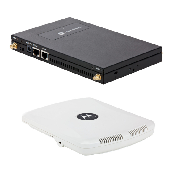
• Verify cable lengths are within the maximum allowable distances for optimal signal transmission. 1.4 Package Contents An AP6522 access point is available in integrated antenna and external antenna models. Contents differ depending on the model ordered. 1.4.1 External Antenna Model Package Contents •... - Page 6 • Lock port for Kensington® style Security Lock The AP6522 access point has one RJ-45 connector supporting an 10/100/1000 Ethernet port and accepts 802.3af-compliant power from an external source. The illustration below is of an integrated antenna model. When operating in a Gigabit Ethernet environment, CAT-5e or CAT-6 cable NOTE is recommended for Gigabit operation.
-
Page 7: Hardware Installation
2.1 Installation Instructions The AP6522 access point mounts either on a wall (with customer supplied M4 x 25 pan head screws and wall anchor - or equivalent) or on a suspended ceiling T-bar. If deploying an external antenna model AP6522 on a suspended ceiling T-bar, access point mounting kit (Part No. -
Page 8: Precautions
2.4 Integrated Antenna Model Wall Mount Instructions Wall mounting requires hanging the AP6522 along its width or length using the two slots on the bottom of the unit. The AP6522 can be mounted on to any plaster, wood, or cement wall surface using customer supplied screw hardware (M3.5 x 0.6 x 20 mm- or equivalent). -
Page 9: Wall Mount Procedure
Installation Guide 2.4.2 Wall Mount Procedure 1. Orient the case on the wall by its width or length. To ensure proper operation of an AP6522 access point, ensure it is CAUTION mounted in the correct orientation as shown above. - Page 10 5. Attach an Ethernet cable from the access point to a controller with an 802.3af-compatible power source or use the PWRS-14000-148R power supply to supply power to the AP6522 (once fully cabled). 6. Place the middle of each of the case’s mount slots over the screw heads.
-
Page 11: Integrated Antenna Model Suspended Ceiling T-Bar Mount
Installation Guide 2.5 Integrated Antenna Model Suspended Ceiling T-Bar Mount Ceiling mount requires holding the AP6522 access point up against a T-bar of a suspended ceiling grid and twisting the case onto the T-bar. 2.5.1 Suspended Ceiling T-Bar Mount Procedure 1. -
Page 12: External Antenna Model Wall Mount Instructions
A wall mount deployment requires hanging the AP6522 access point along its width or length using the pair of slots on the bottom of the unit. The AP6522 can be mounted on to any plaster, wood or cement wall surface using the provided wall anchors. - Page 13 1. Attach the two provided mounting ears (using four ear mounting screws) to the two narrow ens of the AP6522. Align the ears using the built in ear alignment pin on the access point housing. Torque the screws to 6 lb-in.
- Page 14 An existing external antenna model AP300 (WSAP-5100-100) or external antenna model AP650 (AP-0650-660X0) access point, installed on a wall (plenum installation), can be placed by an AP6522. Simply remove the existing legacy model access point from its mounting screws, leave the mounting hardware in place and install the new external antenna model AP6522 directly on to the existing mounting hardware.
-
Page 15: External Antenna Model Suspended Ceiling T-Bar Mount
2.7 External Antenna Model Suspended Ceiling T-Bar Mount Ceiling mount requires holding the AP6522 access point up against a T-bar of a suspended ceiling grid and twisting the case onto the T-bar. If deploying an external antenna model AP6522 on a ceiling T-Bar, access point mounting kit (Part No. - Page 16 5. Attach an Ethernet cable from the access point to a controller with an 802.3af compatible power source or use the PWRS-14000-148R power supply to supply power to the AP6522 (once fully cabled). 6. Attach appropriate antennas to the connectors.
-
Page 17: External Antenna Suspended Ceiling Tile (Plenum) Mount
6. Attach an Ethernet cable from the access point to a controller with an 802.3af compatible power source or use the PWRS-14000-148R power supply to supply power to the AP6522 (once fully cabled). 7. Verify the access point is receiving power by observing the LEDs. -
Page 18: Ap6522 External Antenna Model Antenna Options
2.9 AP6522 External Antenna Model Antenna Options Motorola Solutions supports two antenna suites for AP6522 External Antenna models. One antenna suite supporting the 2.4 GHz band and another antenna suite supporting the 5 GHz band. Select an antenna model best... - Page 19 ML-2452-APAG2A1-01 (Black) Dipole Antenna ML-2452-APAG2A1-02 (White) For up-to-date information on supported antennas and antenna specifications, please refer to the Motorola Solutions Enterprise Wireless LAN Antenna Specification Guide available on the Motorola Solutions Web site. For more information, refer to http://supportcentral.motorola.com/support/product/manuals.do.
-
Page 20: Led Indicators
AP6522 Access Point 2.10 LED Indicators Both Integrated Antenna and External Antenna models have LED activity indicators on the front of the case. With the External Antenna models mounted above a ceiling, LEDs are at the center of an oval badge on the ceiling. - Page 21 Installation Guide Task 5 GHz Activity LED (Amber) 2.4 GHz Activity LED (Green) Unadopted Blink interval at 5 times a second Normal • If this radio band is enabled: • If this radio band is enabled: Operation Blink at 5 second interval Blink at 5 second interval •...
-
Page 22: Initial Access Point Configuration
PWRS-14000-148R power supply to supply power to the AP6522 (once fully cabled). If your host system is a DHCP server, an IP address is automatically assigned to the AP6522 and can be used for device connection. However, if a DHCP server is not available, you’ll need to derive the IP address from the AP6522 MAC address. - Page 23 6. Select the Start Wizard button to run the initial setup wizard. The setup wizard displays the first time the AP6522 user interface is accessed in order to define the AP6522’s initial configuration. 7. If this is the first time the management interface has been accessed, a dialogue displays to start the...
- Page 24 AP6522 Access Point The first page of the Initial AP Setup Wizard displays the Navigation Panel and Introduction for the configuration activities comprising the access point's initial setup A green checkmark to the left of an item in the Navigation Panel defines the listed task as having its minimum required configuration parameters set correctly.
- Page 25 Installation Guide The Introduction screen displays a list of the basic configuration activities supported by the Initial Setup Wizard. 8. Select Save/Commit within each page to save the updates made to that page's configuration. Select Next to proceed to the next page listed in the Navigation Panel. Select Back to revert to the previous screen in the Navigation Panel without saving your updates.
- Page 26 • Standalone AP -Select this option to deploy this access point as an autonomous fat access point. A Standalone AP isn't managed by a Virtual Controller AP, or adopted by a controller. If designating the access point as a Standalone AP, Motorola Solutions recommends NOTE the access point’s UI be used exclusively to define its device configuration, and not...
- Page 27 Installation Guide you’ll also need to define whether the access point receives an IP address using DHCP or if IP resources are provided statically. 11. Select Next. The Initial AP Setup Wizard displays the Access Point Mode screen to define the access point's routing or bridging mode functionality.
- Page 28 AP6522 Access Point 12. Select an Access Point Mode from the available options. • Router Mode - In Router Mode, the access point routes traffic between the local network (LAN) and the Internet or external network (WAN). Router mode is recommended in a deployment supported by just a single access point.
- Page 29 Installation Guide 14. Set the following DHCP and Static IP Address/Subnet information for the LAN interface: • Use DHCP - Select the checkbox to enable an automatic network address configuration using the access point’s DHCP server. • Static IP Address/Subnet - Enter an IP Address and a subnet for the access point's LAN interface. If Use DHCP is selected, this field is not available.
- Page 30 AP6522 Access Point • DNS Forwarding - Select this option to allow a DNS server to translate domain names into IP addresses. If this option is not selected, a primary and secondary DNS resource must be specified. DNS forwarding is useful when a request for a domain name is made but the DNS server, responsible for converting the name into its corresponding IP address, cannot locate the matching IP address.
- Page 31 Installation Guide • Enable NAT on the WAN Interface - Select the checkbox to allow traffic to pass between the access point's WAN and LAN interfaces. 17. Select Next. The Initial AP Setup Wizard displays the Radio Configuration screen to define support for the 2.4GHz radio band, 5GHz radio band or to set the radio's functionality as a dedicated sensor.
- Page 32 AP6522 Access Point • Channel Mode - Select either Random, Best or Static. Select Random for use with a 802.11an radio. To comply with Dynamic Frequency Selection (DFS) requirements in the European Union, the 802.11an radio uses a randomly selected channel each time the access point is powered on.
- Page 33 Installation Guide 20. Set the following parameters for each of the two WLAN configurations available as part of this Initial AP Setup Wizard: • SSID - Enter or modify the Services Set Identification (SSID) associated with the WLAN. The WLAN name is auto-generated using the SSID until changed by the user.
- Page 34 AP6522 Access Point 22. Refer to the Username, Password, Description and Actions columns to review credentials of existing RADIUS Server user accounts. Add new accounts or edit the properties of existing accounts as updates are required. 23. Refer to the Add On-Board RADIUS Server Users field to set the following parameters for a user account: •...
- Page 35 • Location - Define the location of the access point. The Location parameter acts as a reminder of where the AP is deployed within the Motorola Solutions managed wireless network. • Contact - Specify the contact information for the administrator. The credentials provided should accurately reflect the individual responding to service queries.
- Page 36 AP6522 Access Point • Time Zone - Set the time zone where the access point is deployed. This is a required parameter. The setting should be complimentary with the selected deployment country. 27. If an NTP resource is unavailable, set the System Date and Time (calendar date, time and AM/PM designation).
- Page 37 Navigational Panel, or use the Back and Next buttons to scroll to the target screen For information on how use a Motorola Solutions RFS Series controller to manage an AP6522 access point, refer to http://supportcentral.motorola.com/support/product/manuals.do.
-
Page 38: Specifications
Voltage 48V,0.25A (PoE connector) 4.2 AP6522 Integrated Antenna Model Physical Characteristics An AP6522 Integrated Antenna model Access Point has the following physical characteristics: Dimensions 9.38 inches x 7.5 inches x 1.38 inches 23.82 cm x 19.50 cm x 3.50 cm... -
Page 39: Ap6522 External Antenna Model Electrical Characteristics
Installation Guide 4.3 AP6522 External Antenna Model Electrical Characteristics An AP6522 External Antenna model Access Point has the following electrical characteristics: Operating Current & 12VDC, 1A (accessory power connector) Voltage 48V,0.25A (PoE connector) 4.4 AP6522 External Antenna Model Physical Characteristics... -
Page 40: Radio Characteristics
AP6522 Access Point 4.5 Radio Characteristics The AP6522 model Access Points have the following radio characteristics: Operating Channels All channels from 4920 MHz to 5825 MHz except channel 52 -64 Channels 1-13 (2412-2472 MHz) Channel 14 (2484 MHz) Japan only Actual operating frequencies depend on regulatory approval for the country of use. -
Page 41: Regulatory Information
Solutions, Inc. (collectively "Motorola"). This guide applies to Model Number AP6522. The AP6522 access point is approved under MODEL: AP-0622. All Motorola/Symbol devices are designed to be compliant with rules and regulations in locations they are sold and will be labeled as required. -
Page 42: Health And Safety Recommendations
AP6522 Access Point Industry Canada Statement: Caution: The device for the band 5150-5250 MHz is only for indoor usage to reduce potential for harmful interference to co-Channel mobile satellite systems. High power radars are allocated as primary users (meaning they have priority) of 5250-5350 MHz and 5650-5850 MHz and these radars could cause interference and/or damage to LE-LAN devices. -
Page 43: Us And Canada
Power Supply Use ONLY a LISTED Motorola, Type no. PWRS-14000-148R (12VDC @ 4.16A), direct plug-in power supply, marked Class 2 (IEC60950-1, SELV). This device can be powered from a 802.3af compliant power source which is certified by the appropriate agencies. -
Page 44: Radio Transmitters
AP6522 Access Point Radio Frequency Interference Requirements—FCC This equipment has been tested and found to comply with the limits for a Class B digital device, pursuant to Part 15 of the FCC rules. These limits are designed to provide reasonable protection against harmful interference in a residential installation. -
Page 45: Statement Of Compliance
Declarações Regulamentares para AP6522 - Brasil Nota: A marca de certificação se aplica ao Transceptor, modelo AP6522. Este equipamento opera em caráter secundário, isto é, não tem direito a proteção contra interferência prejudicial, mesmo de estações do mesmo tipo, e não pode causar interferência a sistemas operando em caráter primário. - Page 46 AP6522 Access Point Taiwan 5.25-5.35 Korea Turkish WEEE Statement of Compliance EEE Yönetmeliğine Uygundur...
- Page 47 : http://www.motorola.com/recycling/weee. Español: Para clientes en la Unión Europea: todos los productos deberán entregarse a Motorola al final de su ciclo de vida para que sean reciclados. Si desea más información sobre cómo devolver un producto, visite: http://www.motorola.com/recycling/weee.
- Page 48 Motorola-yhtiöön, kun tuotetta ei enää käytetä. Lisätietoja tuotteen palauttamisesta on osoitteessa http://www.motorola.com/recycling/weee. Dansk: Til kunder i EU: Alle produkter skal returneres til Motorola til recirkulering, når de er udtjent. Læs oplysningerne om returnering af produkter på: http://www.motorola.com/recycling/weee. Ελληνικά: Για πελάτες στην Ε.Ε.: Όλα τα προϊόντα, στο τέλος της διάρκειας...
-
Page 49: Part Numbers, Support And Sales
• Software type and version number Motorola Solutions responds to calls by email or telephone within the time limits set forth in support agreements. If you purchased your product from a Motorola Solutions business partner, contact that business partner for support. -
Page 50: Motorola Solutions, Inc. End-User License Agreement
BIND THAT COMPANY, PERSON OR ENTITY. LICENSE GRANT. Subject to the terms of this Agreement, Motorola, Inc. and/or its subsidiaries ("Licensor") hereby grants Licensee a limited, personal, non-sublicensable, non-transferable, nonexclusive license to use the software that Licensee is about to download or install and the documentation that accompanies it (collectively, the "Software") for Licensee's personal use in connection with... - Page 51 FAR, 48 CFR 52.227-14 (JUNE 1987) or DFAR, 48 CFR 252.227-7013 (OCT 1988), as applicable. The "Manufacturer" for purposes of these regulations is Motorola, Inc., One Symbol Plaza, Holtsville, NY 11742. EXPORT RESTRICTIONS. Licensee shall comply with all export laws and restrictions and regulations of the Department of Commerce, the United States Department of Treasury Office of Foreign Assets Control ("OFAC"), or other United States or foreign agency or...
- Page 52 AP6522 Access Point Agreement shall be held by a court or other tribunal of competent jurisdiction to be illegal, invalid or unenforceable, such provisions shall be limited or eliminated to the minimum extent necessary so that this Agreement shall otherwise remain in full force and effect.
-
Page 53: Ap6522 Access Point China Rohs Compliance
塑料和聚合物部件 (Plastic and Polymeric Parts) 光学和光学组件 (Optics and Optical Components) 电池 (Batteries) O: 表示该有毒有害物质在该部件所有均质材料中的含量均在 SJ/T11363-2006 标准规定的限量要求以 下。 X: 表示该有毒有害物质至少在该部件的某一均质材料中的含量超出 SJ/T11363-2006 标准规定的限量 要求。 对销售之日的所售产品,本表表示,公司供应链的电子信息产品可能包含这些物质。注意:在所售产品 中可能会也可能不会含有所有所列的部件。 This table was created to comply with China RoHS requirements for Motorola Solutions‘ AP6522 Access Point. - Page 54 AP6522 Access Point...
- Page 55 Installation Guide...
- Page 56 Schaumburg, IL 60196-1078, U.S.A. http://www.motorolasolutions.com MOTOROLA, MOTO, MOTOROLA SOLUTIONS and the Stylized M Logo are trademarks or registered trademarks of Motorola Trademark Holdings, LLC and are used under license. All other trademarks are the property of their respective owners. © 2012 Motorola Solutions, Inc. All Rights Reserved.