
Related Manuals for KitchenAid KICU508SBL


Summary of Contents for KitchenAid KICU508SBL
-
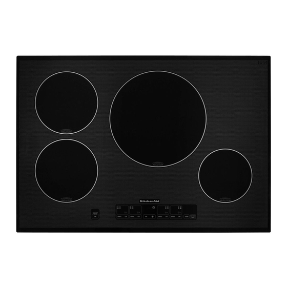
Page 1: Induction Cooktop
KAC-47 TECHNICAL EDUCATION TOUCH-ACTIVATED ELECTRONIC INDUCTION COOKTOP MODELS: KICU508SBL & KICU568SBL JOB AID 4317409... - Page 2 FORWARD This KitchenAid Job Aid “Touch-Activated Electronic Induction Cooktop” (Part No. 4317409), pro- vides the In-Home Service Professional with information on the installation, operation, and service of the Touch-Activated Electronic Induction Cooktop. For specific information on the model being serviced, refer to the “Use and Care Guide,” or “Wiring Diagram” provided with the cooktop.
-
Page 3: Table Of Contents
TABLE OF CONTENTS Page GENERAL ..........................1-1 Cooktop Safety ........................1-1 Model & Serial Number Designations ................1-2 Model & Serial Number Label And Wiring Diagram Locations ........... 1-3 Specifications ........................1-4 INSTALLATION INFORMATION .................... 2-1 Installation Instructions ...................... 2-1 PRODUCT OPERATION ....................... - Page 4 — NOTES — - iv -...
-
Page 5: General
GENERAL COOKTOP SAFETY Your safety and the safety of others are very important. We have provided many important safety messages in this manual and on the appliance. Always read and obey all safety messages. This is the safety alert symbol. This symbol alerts you to potential hazards that can kill or hurt you and others. -
Page 6: Model & Serial Number Designations
MODEL & SERIAL NUMBER DESIGNATIONS MODEL NUMBER PRODUCT GROUP K = KITCHENAID PRODUCT IDENTIFICATION EC = ELECTRIC COOKTOP GC = GAS COOKTOP IC = INDUCTION COOKTOP MERCHANDISING SCHEME C = CERAMIC GLASS S = STANDARD / PORCELAIN METAL T = TEMPERED GLASS... -
Page 7: Model & Serial Number Label And Wiring Diagram Locations
MODEL & SERIAL NUMBER LABEL AND WIRING DIAGRAM LOCATIONS The Model/Serial Number label and Wiring Diagram locations are shown below. Wiring Diagram Location Model & Serial Number (On Bottom Of Cooktop) Label Location... -
Page 8: Specifications
SPECIFICATIONS Model Number KICU508SBL KICU568SBL Model Description Touch Activated 30˝ Ceramic Touch Activated 36˝ Ceramic Premium Black Induction Cooktop Premium Black Induction Cooktop Size-Configuration 30˝ 36˝ Dimensions/Specifications Exterior Dimensions Overall Height (in) 3-1/4˝ 3-1/4˝ Overall Width (in) 31˝ 37˝ Overall Depth (in) 21-9/16˝... - Page 9 Model Number KICU508SBL KICU568SBL Miscellaneous Product Literature Installation Instructions Parts List Service Manual/Job Aid Tech Sheet Use & Care Guide Other Agency Approvals UL, CUL UL, CUL Approved to Install Over BI Oven Hardware Power Cord Length & # Wires...
- Page 10 — NOTES —...
-
Page 11: Installation Information
INSTALLATION INFORMATION INSTALLATION INSTRUCTIONS INSTALL HEAT SHIELD Using two screws, reattach the heat shield to the underside of the cooktop at the Decide on the final location for the cooktop. predrilled holes as shown in the following WARNING illustration. Excessive Weight Hazard Use two or more people to move and install cooktop. - Page 12 Style 2: Cooktop over cabinets Rotate brackets so they do not extend beyond edge of cooktop base. Determine whether your cabinet construc- tion provides clearance for installing clamp- Tighten screws enough to hold brackets ing brackets at cooktop base ends. This in place when cooktop is placed into the cutout.
-
Page 13: Make Electrical Connection
MAKE ELECTRICAL CONNECTION 4-Wire Cable from Home Power Supply IMPORTANT: Use the 4-wire cable from home WARNING power supply in the U.S. where local codes do not allow grounding through neutral, New Branch circuit installations (1996 NEC), mobile homes and recreational vehicles, new construction, and in Canada. - Page 14 ATTACH COOKTOP TO 3-Wire Cable from Home Power Supply - U.S. Only COUNTERTOP IMPORTANT: Use the 3-wire cable from power NOTE: This section applies only if you are using supply where local codes permit a 3-wire con- clamping brackets. nection. A.
-
Page 15: Product Operation
PRODUCT OPERATION THEORY OF OPERATION Principles Of Induction Heating A temperature sensor under the glass is used in order to protect the inductor, and it moreover The use of induction heating in glass-ceramic allows detecting that an empty container is cooking devices has existed since 1987. - Page 16 User-Friendly • As mentioned earlier, induction cooking en- ergy is supplied directly to the cooking utensil • Working conditions are improved with the by the magnetic field; thus, almost all of the absence of smoke and heat produced by source energy gets transferred to that cook- heating equipment.
-
Page 17: Overview Of Induction Cookware
Noises that are Common to the different speeds according to the temperature detected. The fan can also continue operating Normal Operation of Induction when the cooktop is turned off after being Cooktops used if the detected temperature continues Induction heating technology is based on the to be high. -
Page 18: Troubleshooting
TROUBLESHOOTING Nothing will operate Display shows messages • Is the cooktop wired properly? See the In- • Is “E” flashing on the surface cooking stallation Instructions for more information. area display? Thoroughly wipe or remove any object on touch keys. When finished •... - Page 19 • Is the display flashing “Er” and numbers? Operational cooktop sounds If an “Er” and a series of numbers appear in the display panel, turn power off at the circuit • Is there a low humming? This occurs when breaker. Turn on again. If a problem contin- cooking at high power.
- Page 20 — NOTES —...
-
Page 21: Component Access
COMPONENT ACCESS This section instructs you on how to service each component inside the KitchenAid Touch-Activated Electronic Induction Cooktop. The components and their locations are shown below. COMPONENT LOCATIONS Negative Temperature Coefficient (NTC) Sensor (1 For Each Element) Left Induction Element Assembly... -
Page 22: Removing The Cooktop Glass
REMOVING THE COOKTOP GLASS WARNING Remove the fourteen flat-head screws from the front, rear, and side ceramic glass brackets. Remove the two small side brackets from the cooktop base. Electrical Shock Hazard Disconnect power before servicing. Replace all parts and panels before operating. -
Page 23: Removing The Touch Control Board
REMOVING THE TOUCH CONTROL BOARD Press and unlock the two holder tabs, raise WARNING the touch control board, and remove the board from the holder. Touch Control Board Holder Tabs Electrical Shock Hazard Disconnect power before servicing. Slide the three edge connectors off the Replace all parts and panels before touch control board. -
Page 24: Removing An Induction Element Assembly
REMOVING AN INDUCTION ELEMENT ASSEMBLY WARNING Electrical Shock Hazard Disconnect power before servicing. Replace all parts and panels before operating. Left Induction Element Failure to do so can result in death or Mounting Plate Screws (3) electrical shock. Unplug cooktop or disconnect power. Remove the cooktop glass from the cooktop (see page 4-2 for the procedure). - Page 25 Disconnect the induction element assembly Remove the induction element assembly connectors from the electronic board as from the cooktop. follows: Unhook the two cover tabs and remove 2-wire connector at CNT3. the cover from the induction element you 2-wire connector at CNT1. are replacing.
-
Page 26: Removing A Negative Temperature Coefficient (Ntc) Sensor
REMOVING A NEGATIVE TEMPERATURE COEFFICIENT (NTC) SENSOR WARNING Unplug the NTC sensor connector from the electronic board as shown in the chart below. NOTE: If necessary, refer to the Wiring Diagrams in Section 7 for the con- nector locations. ELEMENT LOCATION NTC CONNECTOR CNT3 (LEB) Electrical Shock Hazard... -
Page 27: Removing A Cooling Fan And An Electronic Board
REMOVING A COOLING FAN AND AN ELECTRONIC BOARD WARNING Electronic Board Tabs Cooling Fan Electrical Shock Hazard Disconnect power before servicing. CNT5 Replace all parts and panels before operating. To remove an electronic board: Failure to do so can result in death or a) Remove the cooling fan (see step 4). -
Page 28: Removing A 20A Line Fuse
REMOVING A 20A LINE FUSE LIft the front of the component panel ap- WARNING proximately 8˝, disconnect the 4-wire bridge communication cable connector, and rest the panel back against a sup- port. Component Panel Electrical Shock Hazard Disconnect power before servicing. 4-Wire Bridge Replace all parts and panels before Communication... -
Page 29: Component Testing
COMPONENT TESTING Before testing any of the components, perform Check all connections before replacing • the following checks: components, looking for broken or loose wires, failed terminals, or wires not pressed • The most common cause for control failure into connectors far enough. is corrosion on connectors. -
Page 30: Negative Temperature Coefficient (Ntc) Sensor
WARNING Electrical Shock Hazard Disconnect power before servicing. Replace all parts and panels before operating. Failure to do so can result in death or electrical shock. NEGATIVE TEMPERATURE Temp (°F) R (k Ω) Temp (°F) R (k Ω) COEFFICIENT (NTC) SENSOR 98.264 78.8 47.788... -
Page 31: Electronic Board Ic Check
WARNING Electrical Shock Hazard Disconnect power before servicing. Replace all parts and panels before operating. Failure to do so can result in death or electrical shock. 20A LINE FUSES ELECTRONIC BOARD IC CHECK Electronic Board Refer to page 4-8 for the procedure for access- ing the 20A line fuses. - Page 32 — NOTES —...
-
Page 33: Diagnostics & Troubleshooting
DIAGNOSTICS & TROUBLESHOOTING WARNING Electrical Shock Hazard Disconnect power before servicing. Replace all parts and panels before operating. Failure to do so can result in death or electrical shock. ELECTRONIC BOARD ERROR CODES Error Description Burners Solution No communications between the touch 2 or 4 1. -
Page 34: Touch Control Board Error Codes
TOUCH CONTROL BOARD ERROR CODES Error Description U400 U400 appears static on the display and indicates an acoustic signal when the electronics have been connected erroneously at 400 V. (This warning appears when the measured voltage on the power grids reaches 280 volts, and cases have occurred in which this warning appears at 250 volts). The electric company can divert the supplied voltage by ±7%. -
Page 35: Wiring Diagrams
WIRING DIAGRAMS 30˝ COOKTOP BLACK BLACK... -
Page 36: Cooktop
36˝ COOKTOP... - Page 37 — NOTES —...
- Page 38 — NOTES —...
-
Page 39: Product Specifications
WARRANTY INFORMATION SOURCES IN THE UNITED STATES: FOR PRODUCT SPECIFICATIONS AND WARRANTY INFORMATION CALL: FOR WHIRLPOOL PRODUCTS: 1-800-253-1301 FOR KITCHENAID PRODUCTS: 1-800-422-1230 FOR ROPER PRODUCTS: 1-800-447-6737 FOR TECHNICAL ASSISTANCE WHILE AT THE CUSTOMER’S HOME CALL: THE TECHNICAL ASSISTANCE LINE: 1-800-832-7174...