Table of Contents
Advertisement
Quick Links
Advertisement
Table of Contents

Related Manuals for Asus Desktop PC T2-AE1


Summary of Contents for Asus Desktop PC T2-AE1
- Page 1 Terminator 2 Barebone System Model T2-AE1...
- Page 2 Product warranty or service will not be extended if: (1) the product is repaired, modified or altered, unless such repair, modification of alteration is authorized in writing by ASUS; or (2) the serial number of the product is defaced or missing.
-
Page 3: Table Of Contents
Table of contents Notices ... vi Safety information ... vii About this guide ... viii System package contents ... x Chapter 1: System Introduction Chapter 1: System Introduction Chapter 1: System Introduction Chapter 1: System Introduction Chapter 1: System Introduction Welcome! ... - Page 4 Creating a bootable floppy disk ... 5-2 5.1.2 ASUS EZ Flash utility ... 5-3 5.1.3 AFUDOS utility ... 5-4 5.1.4 ASUS CrashFree BIOS 2 utility ... 5-6 5.1.5 ASUS Update utility ... 5-8 BIOS setup program ... 5-11 5.2.1 BIOS menu screen ... 5-12 5.2.2...
- Page 5 Table of contents Main menu ... 5-14 5.3.1 System Time ... 5-14 5.3.2 System Date ... 5-14 5.3.3 Legacy Diskette A ... 5-14 5.3.4 Primary IDE Master/Slave ... 5-15 5.3.5 Onboard PCI S-ATA Controller ... 5-16 5.3.6 System Information ... 5-17 Advanced menu ...
-
Page 6: Notices
Notices Federal Communications Commission Statement Federal Communications Commission Statement Federal Communications Commission Statement Federal Communications Commission Statement Federal Communications Commission Statement This device complies with Part 15 of the FCC Rules. Operation is subject to the following two conditions: • This device may not cause harmful interference, and •... -
Page 7: Safety Information
Safety information Electrical safety Electrical safety Electrical safety Electrical safety Electrical safety • To prevent electrical shock hazard, disconnect the power cable from the electrical outlet before relocating the system. • When adding or removing devices to or from the system, ensure that the power cables for the devices are unplugged before the signal cables are connected. -
Page 8: About This Guide
Audience Audience Audience This guide provides general information and installation instructions about the ASUS Terminator 2 barebone system. This guide is intended for experienced users and integrators with hardware knowledge of personal computers. How this guide is organized How this guide is organized... - Page 9 A S U S W e b s i t e s A S U S W e b s i t e s The ASUS websites worldwide provide updated information on ASUS hardware and software products. Refer to the ASUS contact information.
-
Page 10: System Package Contents
A S U S T e r m i n a t o r 2 b a r e b o n e s y s t e m with • ASUS motherboard • 200 W Passive PFC power supply unit •... - Page 11 Chapter 1 This chapter gives a general description of the ASUS Terminator 2. The chapter lists the system features including introduction on the front and rear panel, and internal components. A S U S T 2 - A E 1...
-
Page 12: Chapter 1: System Introduction
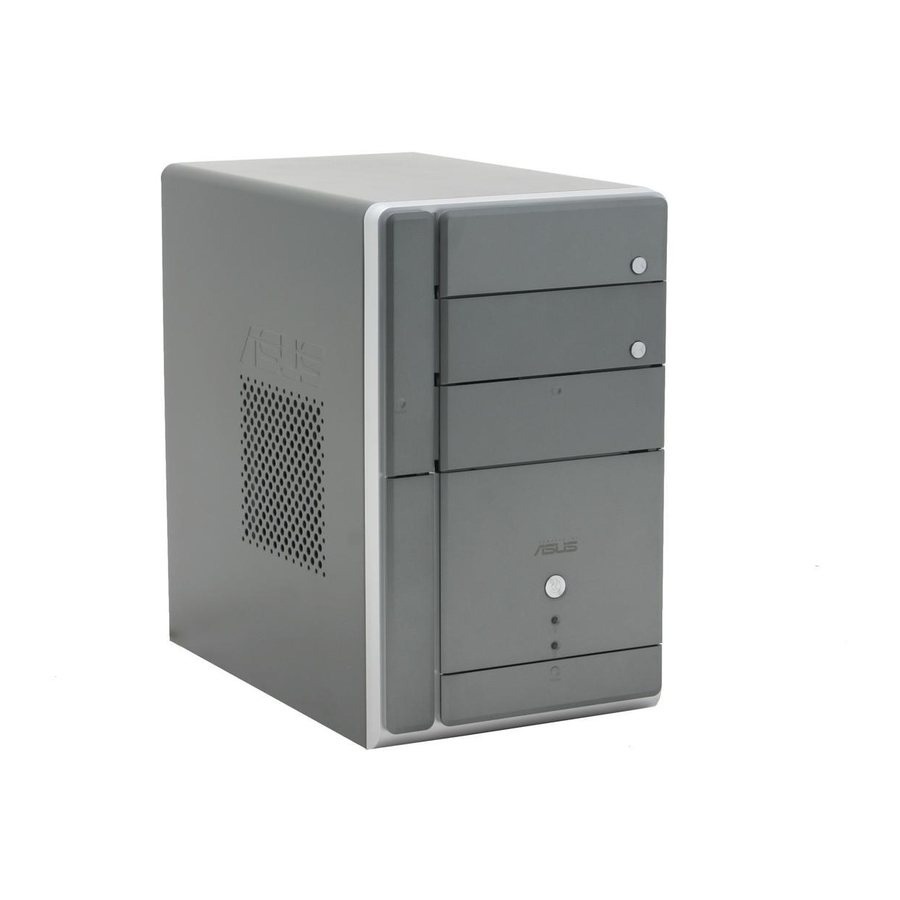
The ASUS Terminator 2 is an all-in-one barebone system with a versatile home entertainment feature. The system comes in a stylish mini-tower casing, and powered by the ASUS motherboard that supports the AMD Athlon™ 64/Athlon™ XP processor with 800 MHz FSB and up to 2 GB system memory. -
Page 13: Drive Bay
1 . 1 . F l o p p y d r i v e d o o r . F l o p p y d r i v e d o o r . Open this door to access the floppy disk drive. F l o p p y d r i v e d o o r . -
Page 14: Front Panel (Internal)
Front panel (internal) The optical drive(s), storage card reader slots, and several I/O ports are located inside the front panel doors. Open the front panel doors by pressing the 9 . 9 . F l o p p y d i s k d r i v e . F l o p p y d i s k d r i v e . -
Page 15: Rear Panel
Rear panel The system rear panel includes the power connector and several I/O ports that allow convenient connection of devices. 1 1 1 1 1 2 2 2 2 2 3 3 3 3 3 4 4 4 4 4 5 5 5 5 5 6 6 6 6 6 7 7 7 7 7... -
Page 16: Expansion Cards
9 . 9 . L i n e I n p o r t L i n e I n p o r t L i n e I n p o r t L i n e I n p o r t L i n e I n p o r t player or other audio sources. -
Page 17: Internal Components
Optical drive (optional) 5.25-inch empty optical drive bay Floppy disk drive (optional) Front panel cover Hard disk drive metal tray Chassis fan ASUS motherboard DIMM sockets CPU heatsink and fan 10. AGP slot 11. PCI slot 12. Serial ATA connectors 13. - Page 18 1 - 8 1 - 8 1 - 8 1 - 8 1 - 8 C h a p t e r 1 : S y s t e m i n t r o d u c t i o n C h a p t e r 1 : S y s t e m i n t r o d u c t i o n C h a p t e r 1 : S y s t e m i n t r o d u c t i o n C h a p t e r 1 : S y s t e m i n t r o d u c t i o n...
- Page 19 Chapter 2 This chapter provides step-by-step instructions on how to install components in the system. A S U S T 2 - A E 1 A S U S T 2 - A E 1 A S U S T 2 - A E 1 A S U S T 2 - A E 1 A S U S T 2 - A E 1...
-
Page 20: Chapter 2: Basic Installation
Preparation Before you proceed, make sure that you have all the components you plan to install in the system. Basic components to install Basic components to install Basic components to install Basic components to install Basic components to install 1. Central processing unit (CPU) 2. -
Page 21: Removing The Cover
Removing the cover To remove the cover: On the rear panel, locate the three screws that secure the cover to the chassis. Use a Phillips screw driver to remove the cover screws. Keep the screws for later use. Slightly pull the cover toward the rear panel until the side tabs are disengaged from the chassis. -
Page 22: Removing The Power Supply
Removing the power supply You must remove the power supply unit (PSU) before you can install a central processing unit( CPU) and other system components. To remove the PSU: Lay the system on its side on a flat, stable surface. Disconnect the optical drive and floppy disk drive power plugs. -
Page 23: Installing A Cpu
Installing a CPU The motherboard comes with a surface mount 754-pin Zero Insertion Force (ZIF) socket designed for the AMD Athlon™ 64 processor in the 754-pin lidded ceramic micro PGA package. Take note of the marked corner (with gold triangle) on the CPU. This mark should match a specific corner on the socket to ensure correct installation. - Page 24 Unlock the socket by pressing the lever sideways, then lift it up to a 90°-100° angle. Make sure that the socket lever is lifted up to 90°-100° angle, otherwise the CPU does not fit in completely. Position the CPU above the socket such that the CPU corner with the gold triangle matches the socket corner with a small...
-
Page 25: Installing The Cpu Fan And Heatsink Assembly
Installing the CPU fan and heatsink assembly Make sure to turn off your computer and unplug the cable from the power source before installing the CPU fan and heatsink assembly. To install the CPU fan and heatsink assembly: Remove the CPU fan and heatsink assembly from its packaging and vacuum cover. -
Page 26: Installing A Dimm
Installing a DIMM The system motherboard comes with two Double Data Rate (DDR) Dual Inline Memory Module (DIMM) sockets. The following figure illustrates the location of the sockets: ® 184-pin DDR DIMM sockets 2.7.1 2.7.1 2.7.1 Memory configurations Memory configurations Memory configurations 2.7.1 2.7.1... - Page 27 512MB Hynix HY5DU56822DT-D43 Obtain DDR DIMMs only from ASUS qualified vendors. Refer to the Qualified DDR400 vendors list on this page. Visit the ASUS website (www.asus.com) for the latest DDR Qualified Vendors List. A S U S T 2 - A E 1...
-
Page 28: Dimm Installation
2.7.2 2.7.2 2.7.2 DIMM installation DIMM installation DIMM installation 2.7.2 2.7.2 DIMM installation DIMM installation To install a DDR DIMM. Locate the two DIMM sockets on the motherboard. Unlock a socket by pressing the retaining clips outward. Align a DIMM on the socket such that the notch on the DIMM matches the break on the socket. -
Page 29: Installing An Expansion Card
Installing an expansion card In the future, you may need to install expansion cards. The motherboard has one PCI and one AGP 8X slot. The following sub-sections describe the slots and the expansion cards that they support. Make sure to unplug the power cord before adding or removing expansion cards. -
Page 30: Expansion Card Installation
2.8.3 2.8.3 2.8.3 Expansion card installation Expansion card installation Expansion card installation 2.8.3 2.8.3 Expansion card installation Expansion card installation To install an expansion card. Before installing the expansion card, read the documentation that came with it and make the necessary hardware settings for the card. Pull the expansion card lock to the direction of the arrow. -
Page 31: Configuring An Expansion Card
2.8.4 2.8.4 2.8.4 Configuring an expansion card Configuring an expansion card Configuring an expansion card 2.8.4 2.8.4 Configuring an expansion card Configuring an expansion card After installing the expansion card, configure it by adjusting the software settings. Turn on the system and change the necessary BIOS settings, if any. See Chapter 5 for information on BIOS setup. -
Page 32: Installing An Optical Drive
Installing an optical drive The Terminator 2 system comes with two 5.25-inch drive bays for two optical drives. • You may install a second optical drive only if you installed a Serial ATA hard disk drive. • Set your second optical drive as Slave device before connecting the IDE cable and power plug. - Page 33 Carefully push the optical drive into the bay until its screw holes align with the holes on the bay as shown. Secure the optical drive with two screws on one side of the bay. Connect a power cable from the power supply unit to the power connector at the back of the optical drive.
- Page 34 13. Reinstall the front panel cover by aligning its hooks with the chassis holes. 14. Lock the front panel cover hooks to the chassis holes as indicated. 2 - 1 6 2 - 1 6 2 - 1 6 2 - 1 6 2 - 1 6 1 1 1 1 1 3 3 3 3 3 C h a p t e r 2 : B a s i c i n s t a l l a t i o n...
-
Page 35: 2.10 Installing A Floppy Disk Drive
2.10 Installing a floppy disk drive The Terminator 2 system comes with one 3.25-inch drive bay for a floppy disk drive. To install a floppy disk drive: Remove the front panel cover. For instructions on how to remove the front panel cover, refer to steps 1-5 of section “2.8 Installing an optical drive.”... -
Page 36: Installing A Hard Disk Drive (Hdd)
2.11 Installing a hard disk drive (HDD) The system supports one Ultra ATA/133 IDE or one Serial ATA hard disk drive. To install an IDE hard disk drive: Locate the HDD tray lock screw on the other side of the chassis. Remove the lock screw with a Philips screw driver. - Page 37 Reinstall the tray and the HDD to the chassis by locking the tray slots to the chassis hooks. Secure the tray with the screw you removed earlier. Connect one end of the 40-pin IDE cable to the IDE connector on the drive. Connect a 4-pin power plug from the power supply unit to the HDD power connector.
-
Page 38: 2.12 Reinstalling The Power Supply Unit
2.12 Reinstalling the power supply unit Reinstall the power supply unit (PSU) after installing the system components and reconnecting the cables, . To reinstall the PSU: Connect the 4-pin 12 V power plug to the ATX12V connector on the motherboard. See page 4-10 for the location of this connectors. -
Page 39: Power Supply Specifications
Power supply unit plugs Connect the 4-pin power plug to the power connector of the floppy disk drive. Connect the 4-pin power plug(s) to the power connector of the optical drive(s) or hard disk drive. Connect the 4-pin power plug to the power connector of the Serial ATA (SATA) drive. -
Page 40: 2.13 Replacing The Cover
2.13 Replacing the cover To replace the cover: Turn the chassis upright. Position the front edge of the cover at least two inches from the front panel cover. Fit the cover tabs with the chassis rail and the front panel tabs. Lower the rear edge of the cover as shown. -
Page 41: 2.14 Connecting External Devices
2.14 Connecting external devices To the front panel To the front panel To the front panel To the front panel To the front panel H e a d p h o n e H e a d p h o n e M i c M i c H e a d p h o n e... - Page 42 To the rear panel To the rear panel To the rear panel To the rear panel To the rear panel J o y s t i c k J o y s t i c k J o y s t i c k J o y s t i c k J o y s t i c k Serial mouse...
- Page 43 Chapter 3 This chapter helps you power up the system and install drivers and utilities from the support CD. A S U S T 2 - A E 1 A S U S T 2 - A E 1 A S U S T 2 - A E 1 A S U S T 2 - A E 1 A S U S T 2 - A E 1...
-
Page 44: Chapter 3: Starting Up
Screen display and driver options may not be the same for other operating system versions. • The contents of the support CD are subject to change at any time without notice. Visit the ASUS website for updates. 3 - 2 3 - 2 3 - 2... -
Page 45: Running The Support Cd
3.3.1 3.3.1 3.3.1 Running the support CD Running the support CD Running the support CD 3.3.1 3.3.1 Running the support CD Running the support CD To begin using the support CD, place the CD in your optical drive. The CD automatically displays the D r i v e r s computer. -
Page 46: Utilities Menu
SiS191/SiS190 Ethernet Device Driver SiS191/SiS190 Ethernet Device Driver SiS191/SiS190 Ethernet Device Driver SiS191/SiS190 Ethernet Device Driver SiS191/SiS190 Ethernet Device Driver Installs the SiS191/SiS190 ethernet device driver. SiS180/182 RAID Controller Drivers SiS180/182 RAID Controller Drivers SiS180/182 RAID Controller Drivers SiS180/182 RAID Controller Drivers SiS180/182 RAID Controller Drivers Installs the SiS180/182 RAID controller drivers. - Page 47 ASUS Radio Application ASUS Radio Application ASUS Radio Application ASUS Radio Application ASUS Radio Application Installs the ASUS radio application that allows you to tune in to an FM radio station. See page 3-9 for details. ASUS Screensaver ASUS Screensaver ASUS Screensaver...
-
Page 48: Asus Contact Information
3.3.4 3.3.4 ASUS contact information ASUS contact information ASUS contact information 3.3.4 3.3.4 ASUS contact information ASUS contact information The Contact tab displays the ASUS contact information. 3.3.5 3.3.5 3.3.5 Other information Other information Other information 3.3.5 3.3.5 Other information... -
Page 49: Software Information
Instant Music does not work if you installed and enabled an add-on sound card. • Instant Music only supports PS/2 keyboard. To enable ASUS Instant Music: To enable ASUS Instant Music: To enable ASUS Instant Music: To enable ASUS Instant Music:... - Page 50 To use ASUS Instant Music: Connect the PC power plug to an electrical outlet. Use either one of the two sets of special function keys on your keyboard to play audio CDs. These keys only function as indicated if you enabled the Instant Music item in BIOS.
-
Page 51: Asus Radio Player
3.4.2 ASUS Radio Player ASUS Radio Player ASUS Radio Player allows you to tune in to an FM station using the optional radio module. By default, the radio region of the ASUS FM radio module is set to E u r o p e... - Page 52 Storing a radio station Storing a radio station Storing a radio station Storing a radio station Storing a radio station To store a radio station: Use the S c a n S c a n or T u n e S c a n S c a n S c a n...
- Page 53 Chapter 4 This chapter gives information about the motherboard that comes with the system. This chapter includes the motherboard layout, jumper settings, and connector locations. A S U S T 2 - A E 1 A S U S T 2 - A E 1 A S U S T 2 - A E 1 A S U S T 2 - A E 1 A S U S T 2 - A E 1...
-
Page 54: Introduction
Introduction The ASUS Terminator 2 motherboard comes already installed in the ASUS Terminator 2 system. This chapter provides technical information about the motherboard for future upgrades or system reconfiguration. Motherboard layout IOC_MB KBMS ATX12V Line Line ALC655 CHA_FAN USB12 FP_AUDIO... -
Page 55: Jumpers
Jumpers 1 . 1 . C l e a r R T C R A M ( C L R T C ) C l e a r R T C R A M ( C L R T C ) C l e a r R T C R A M ( C L R T C ) C l e a r R T C R A M ( C L R T C ) C l e a r R T C R A M ( C L R T C ) - Page 56 2 . 2 . U S B d e v i c e w a k e - u p ( 3 - p i n U S B P W R 1 2 , U S B P W R 3 4 ) U S B d e v i c e w a k e - u p ( 3 - p i n U S B P W R 1 2 , U S B P W R 3 4 ) U S B d e v i c e w a k e - u p ( 3 - p i n U S B P W R 1 2 , U S B P W R 3 4 ) U S B d e v i c e w a k e - u p ( 3 - p i n U S B P W R 1 2 , U S B P W R 3 4 )
-
Page 57: Connectors
Connectors This section describes and illustrates the connectors on the motherboard. See page 1-7 for the description of rear panel connectors. 1 . 1 . F r o n t p a n e l U S B c o n n e c t o r ( 1 0 - 1 p i n U S B 5 6 ) F r o n t p a n e l U S B c o n n e c t o r ( 1 0 - 1 p i n U S B 5 6 ) F r o n t p a n e l U S B c o n n e c t o r ( 1 0 - 1 p i n U S B 5 6 ) F r o n t p a n e l U S B c o n n e c t o r ( 1 0 - 1 p i n U S B 5 6 ) - Page 58 3 . 3 . I E E E 1 3 9 4 a c o n n e c t o r s ( 6 - p i n I E 1 394_1, 8-pin IE1394_0) I E E E 1 3 9 4 a c o n n e c t o r s ( 6 - p i n I E 1 3 I E E E 1 3 9 4 a c o n n e c t o r s ( 6 - p i n I E 1 3 I E E E 1 3 9 4 a c o n n e c t o r s ( 6 - p i n I E 1 3 I E E E 1 3 9 4 a c o n n e c t o r s ( 6 - p i n I E 1 3...
- Page 59 5 . 5 . I / O e x t e n s i o n m o d u l e ( 2 2 - p i n I O C _ M B ) I / O e x t e n s i o n m o d u l e ( 2 2 - p i n I O C _ M B ) I / O e x t e n s i o n m o d u l e ( 2 2 - p i n I O C _ M B ) I / O e x t e n s i o n m o d u l e ( 2 2 - p i n I O C _ M B ) I / O e x t e n s i o n m o d u l e ( 2 2 - p i n I O C _ M B )
- Page 60 7 . 7 . A T X p o w e r c o n n e c t o r s ( 2 0 - p i n A T X P W R , 4 - p i n A T X 1 2 V ) A T X p o w e r c o n n e c t o r s ( 2 0 - p i n A T X P W R , 4 - p i n A T X 1 2 V ) A T X p o w e r c o n n e c t o r s ( 2 0 - p i n A T X P W R , 4 - p i n A T X 1 2 V ) A T X p o w e r c o n n e c t o r s ( 2 0 - p i n A T X P W R , 4 - p i n A T X 1 2 V )
-
Page 61: Hard Disk Drives
9 . 9 . S e r i a l A T A c o n n e c t o r s S e r i a l A T A c o n n e c t o r s S e r i a l A T A c o n n e c t o r s S e r i a l A T A c o n n e c t o r s S e r i a l A T A c o n n e c t o r s... - Page 62 1 0 . 1 0 . I n t e r n a l a u d i o c o n n e c t o r s ( 4 - p i n A U X , C D ) 1 0 .
- Page 63 1 2 . 1 2 . S y s t e m p a n e l c o n n e c t o r ( 8 - 1 p i n P A N E L ) 1 2 . S y s t e m p a n e l c o n n e c t o r ( 8 - 1 p i n P A N E L ) S y s t e m p a n e l c o n n e c t o r ( 8 - 1 p i n P A N E L ) S y s t e m p a n e l c o n n e c t o r ( 8 - 1 p i n P A N E L )
- Page 64 4 - 1 2 4 - 1 2 4 - 1 2 4 - 1 2 4 - 1 2 C h a p t e r 4 : M o t h e r b o a r d i n f o C h a p t e r 4 : M o t h e r b o a r d i n f o C h a p t e r 4 : M o t h e r b o a r d i n f o C h a p t e r 4 : M o t h e r b o a r d i n f o...
- Page 65 Chapter 5 This chapter tells how to change system settings through the BIOS Setup menus and describes the BIOS parameters. A S U S T 2 - A E 1 A S U S T 2 - A E 1 A S U S T 2 - A E 1 A S U S T 2 - A E 1 A S U S T 2 - A E 1...
-
Page 66: Managing And Updating Your Bios
Refer to the corresponding sections for details on these utilities. Save a copy of the original motherboard BIOS file to a bootable floppy disk in case you need to restore the BIOS in the future. Copy the original motherboard BIOS using the ASUS Update or AFUDOS utilities. 5.1.1 5.1.1... -
Page 67: Asus Ez Flash Utility
ASUS EZ Flash utility ASUS EZ Flash utility The ASUS EZ Flash feature allows you to update the BIOS without having to go through the long process of booting from a floppy disk and using a DOS-based utility. The EZ Flash utility is built-in the BIOS chip so it is accessible by pressing <Alt>... -
Page 68: Afudos Utility
5.1.3 5.1.3 5.1.3 AFUDOS utility AFUDOS utility AFUDOS utility 5.1.3 5.1.3 AFUDOS utility AFUDOS utility The AFUDOS utility allows you to update the BIOS file in DOS environment using a bootable floppy disk with the updated BIOS file. This utility also allows you to copy the current BIOS file that you can use as backup when the BIOS fails or gets corrupted during the updating process. - Page 69 Updating the BIOS file To update the BIOS file using the AFUDOS utility: Visit the ASUS website (www.asus.com) and download the latest BIOS file for the motherboard. Save the BIOS file to a bootable floppy disk. Write the BIOS filename on a piece of paper. You need to type the exact BIOS filename at the DOS prompt.
-
Page 70: Asus Crashfree Bios 2 Utility
ASUS CrashFree BIOS 2 utility ASUS CrashFree BIOS 2 utility The ASUS CrashFree BIOS 2 is an auto recovery tool that allows you to restore the BIOS file when it fails or gets corrupted during the updating process. You can update a corrupted BIOS file using the motherboard support CD or the floppy disk that contains the updated BIOS file. - Page 71 The utility displays the following message and automatically checks the floppy disk for the original or updated BIOS file. Bad BIOS checksum. Starting BIOS recovery... Checking for floppy... When found, the utility reads the BIOS file and starts flashing the corrupted BIOS file.
-
Page 72: Asus Update Utility
ASUS Update utility ASUS Update utility ASUS Update utility ASUS Update utility The ASUS Update is a utility that allows you to manage, save, and update the motherboard BIOS in Windows allows you to: • Save the current BIOS file •... - Page 73 Updating the BIOS through the Internet To update the BIOS through the Internet: Launch the ASUS Update utility from the Windows S t a r t > P r o g r a m s S t a r t...
- Page 74 S t a r t A S U S U p d a t e A S U S U p d a t e. The ASUS Update main window appears. A S U S U p d a t e...
-
Page 75: Bios Setup Program
• Visit the ASUS website (www.asus.com) to download the latest BIOS file for this motherboard. A S U S T 2 - A E 1 A S U S T 2 - A E 1... -
Page 76: Bios Menu Screen
[Thu,01/06/2005] [1.44M, 3.5 in.] [ST320410A] [ASUS CD-S520/A] [Disabled] C h a p t e r 5 : B I O S s e t u p C h a p t e r 5 : B I O S s e t u p... -
Page 77: Menu Items
[1.44M, 3.5 in] Primary IDE Master : [ST320410A] Primary IDE Slave : [ASUS CD-S520/A] Onboard PCI S-ATA controller [Disabled] System Information M a i n m e n u i t e m s M a i n m e n u i t e m s... -
Page 78: Main Menu
[Thu,01/06/2005] [1.44M, 3.5 in.] [ST320410A] [ASUS CD-S520/A] [RAID By ROM] C h a p t e r 5 : B I O S s e t u p C h a p t e r 5 : B I O S s e t u p... -
Page 79: Primary Ide Master/Slave
5.3.4 5.3.4 5.3.4 Primary IDE Master/Slave Primary IDE Master/Slave Primary IDE Master/Slave 5.3.4 5.3.4 Primary IDE Master/Slave Primary IDE Master/Slave While entering Setup, the BIOS automatically detects the presence of IDE devices. There is a separate sub-menu for each IDE device. Select a device item then press <Enter>... -
Page 80: Onboard Pci S-Ata Controller
PIO Mode [Auto] PIO Mode [Auto] PIO Mode [Auto] PIO Mode [Auto] PIO Mode [Auto] Selects the PIO mode. Configuration options: [Auto] [0] [1] [2] [3] [4] DMA Mode [Auto] DMA Mode [Auto] DMA Mode [Auto] DMA Mode [Auto] DMA Mode [Auto] Selects the DMA mode. -
Page 81: System Information
5.3.6 5.3.6 5.3.6 System Information System Information System Information 5.3.6 5.3.6 System Information System Information This menu gives you an overview of the general system specifications. The BIOS automatically detects the items in this menu. AMIBIOS Version : 0117 Build Date : 02/21/05 Processor Type : AMD Athlon (tm) 64 Processor 3200+... -
Page 82: Advanced Menu
Advanced menu The Advanced menu items allow you to change the settings for the CPU and other system devices. Take caution when changing the settings of the Advanced menu items. Incorrect field values can cause the system to malfunction. CPU Configuration Chipset Onboard Devices Configuration PCI PnP... - Page 83 Memory Configuration Memory Configuration Memory Configuration Memory Configuration Memory Configuration CPU Configuration Burst length Memclock Mode Memory CLK CAS Latency TRCD TRAS Burst length [4 Beats] Sets the burst length. Configuration options: [8 Beats] [4 Beats] [2 Beats] Memclock Mode [Auto] [Auto] allows the BIOS to set the memclock mode automatically.
-
Page 84: Chipset
5.4.2 5.4.2 5.4.2 Chipset Chipset Chipset 5.4.2 5.4.2 Chipset Chipset Chipset Settings AGP Configuration Hyper Transport Configuration MPS Configuration AGP Configuration AGP Configuration AGP Configuration AGP Configuration AGP Configuration AGP Configuration Aperture Size Graphic Adapter Priority AGP FAST WRITE Select AGP 3.0 Data Ratio Share Memory Aperture Size [64 MB] Configuration options: [32 MB] [64 MB] 128 MB]... - Page 85 HyperTransport Configuration HyperTransport Configuration HyperTransport Configuration HyperTransport Configuration HyperTransport Configuration HyperTransport Configuration HT Width HT Speed HT Width [ 8x16 BIT] Configuration options: [8x8 BIT] [16x16 BIT] [16x8 BIT] [8x16 BIT] HT Speed [800 MHz] Configuration options: [200 MHz] [400 MHz] [600 MHz] [800 MHz] MPS Configuration MPS Configuration MPS Configuration...
-
Page 86: Onboard Devices Configuration
5.4.3 5.4.3 Onboard Devices Configuration Onboard Devices Configuration 5.4.3 5.4.3 5.4.3 Onboard Devices Configuration Onboard Devices Configuration Onboard Devices Configuration Onboard AC97 Audio Device Onboard SiS190 LAN Device SiS190 LAN Boot ROM USB Configuration Serial Port1 Address Parallel Port Address Parallel Port Mode ECP Mode DMA Channel Parallel Port IRQ... - Page 87 USB Configuration USB Configuration USB Configuration USB Configuration USB Configuration The items in this menu allow you to change the USB-related features. Select an item then press <Enter> to display the configuration options. USB Configuration USB Devices Enabled: None Onboard SiS USB1.1 Device Onboard SiS USB2.0 Device Legacy USB Support USB 2.0 Controller Mode...
- Page 88 Serial Port1 Address [3F8/IRQ4] Serial Port1 Address [3F8/IRQ4] Serial Port1 Address [3F8/IRQ4] Serial Port1 Address [3F8/IRQ4] Serial Port1 Address [3F8/IRQ4] Allows you to select the Serial Port1 base address. Configuration options: [Disabled] [3F8/IRQ4] [2F8/IRQ3] [3E8/IRQ4] [2E8/IRQ3] Parallel Port Address [378] Parallel Port Address [378] Parallel Port Address [378] Parallel Port Address [378]...
-
Page 89: Pci Pnp
5.4.4 5.4.4 5.4.4 PCI PnP PCI PnP PCI PnP 5.4.4 5.4.4 PCI PnP PCI PnP The PCI PnP menu items allow you to change the advanced settings for PCI/PnP devices. The menu includes setting IRQ and DMA channel resources for either PCI/PnP or legacy ISA devices, and setting the memory size block for legacy ISA devices. - Page 90 PCI IDE BusMaster [Enabled] PCI IDE BusMaster [Enabled] PCI IDE BusMaster [Enabled] PCI IDE BusMaster [Enabled] PCI IDE BusMaster [Enabled] Allows BIOS to use PCI bus mastering when reading/writing to IDE devices. Configuration options: [Disabled] [Enabled] OffBoard PCI/ISA IDE Card [Auto] OffBoard PCI/ISA IDE Card [Auto] OffBoard PCI/ISA IDE Card [Auto] OffBoard PCI/ISA IDE Card [Auto]...
-
Page 91: Instant Music Configuration
5.4.5 5.4.5 Instant Music Configuration Instant Music Configuration 5.4.5 5.4.5 5.4.5 Instant Music Configuration Instant Music Configuration Instant Music Configuration Instant Music Option Instant Music Instant Music [Disabled] Instant Music [Disabled] Instant Music [Disabled] Instant Music [Disabled] Instant Music [Disabled] Enables or disables the Instant Music feature. -
Page 92: Power Menu
Power menu The Power menu items allow you to change the settings for the ACPI and Advanced Power Management (APM). Select an item then press <Enter> to display the configuration options. Suspend Mode Repost Video on S3 Resume ACPI 2.0 Support ACPI APIC Support APM Configuration Hardware Monitor... -
Page 93: Apm Configuration
5.5.5 5.5.5 5.5.5 APM Configuration APM Configuration APM Configuration 5.5.5 5.5.5 APM Configuration APM Configuration APM Configuration Power Button Mode Restore on AC Power Loss Resume on Ring Resume on LAN Resume on PME# Resume On Keyboard Resume PS/2 Mouse Resume On RTC Power Button Mode [On/Off] Power Button Mode [On/Off]... -
Page 94: Hardware Monitor
Resume on PS/2 Mouse [Disabled] Resume on PS/2 Mouse [Disabled] Resume on PS/2 Mouse [Disabled] Resume on PS/2 Mouse [Disabled] Resume on PS/2 Mouse [Disabled] When set to [Enabled], this parameter allows you to use the PS/2 mouse to turn on the system. This feature requires an ATX power supply that provides at least 1A on the +5VSB lead. - Page 95 CPU Q-Fan Control [Enabled] CPU Q-Fan Control [Enabled] Allows you to enable or disable the ASUS Q-Fan feature that smartly adjusts the fan speeds for more efficient system operation. When this field is set to [Enabled], the three succeeding items appear. Configuration...
-
Page 96: Boot Menu
[PM-ST320410A] [PS-ASUS CD-S520/A] C h a p t e r 5 : B I O S s e t u p C h a p t e r 5 : B I O S s e t u p... -
Page 97: Boot Settings Configuration
This allows you to enable or disable the full screen logo display feature. Configuration options: [Disabled] [Enabled] Set this item to [Enabled] to use the ASUS MyLogo™ feature. Add On ROM Display Mode [Force BIOS] Add On ROM Display Mode [Force BIOS]... -
Page 98: Security
Hit ‘DEL’ Message Display [Enabled] Hit ‘DEL’ Message Display [Enabled] Hit ‘DEL’ Message Display [Enabled] Hit ‘DEL’ Message Display [Enabled] Hit ‘DEL’ Message Display [Enabled] When set to Enabled, the system displays the message “Press DEL to run Setup” during POST. Configuration options: [Disabled] [Enabled] Interrupt 19 Capture [Disabled] Interrupt 19 Capture [Disabled] Interrupt 19 Capture [Disabled]... - Page 99 If you forget your BIOS password, you can clear it by erasing the CMOS Real Time Clock (RTC) RAM. See section “4.3 Jumpers” for information on how to erase the RTC RAM. After you have set a supervisor password, the other items appear to allow you to change other security settings.
-
Page 100: Exit Menu
The message “Password Installed” appears after you set your password successfully. To change the user password, follow the same steps as in setting a user password. Clear User Password Clear User Password Clear User Password Clear User Password Clear User Password Select this item to clear the user password. - Page 101 Exit & Save Changes Exit & Save Changes Exit & Save Changes Exit & Save Changes Exit & Save Changes Once you are finished making your selections, choose this option from the Exit menu to ensure the values you selected are saved to the CMOS RAM. An onboard backup battery sustains the CMOS RAM so it stays on even when the PC is turned off.
- Page 102 5 - 3 8 5 - 3 8 5 - 3 8 5 - 3 8 5 - 3 8 C h a p t e r 5 : B I O S s e t u p C h a p t e r 5 : B I O S s e t u p C h a p t e r 5 : B I O S s e t u p C h a p t e r 5 : B I O S s e t u p C h a p t e r 5 : B I O S s e t u p...
-
Page 103: Appendix
Appendix The Appendix includes the power supply unit specification for this system. A S U S T 2 - A E 1 A S U S T 2 - A E 1 A S U S T 2 - A E 1 A S U S T 2 - A E 1 A S U S T 2 - A E 1... -
Page 104: Power Supply Specifications
Power supply specifications Input characteristics Input characteristics Input characteristics Input characteristics Input characteristics I n p u t V o l t a g e R a n g e I n p u t V o l t a g e R a n g e I n p u t V o l t a g e R a n g e I n p u t V o l t a g e R a n g e I n p u t V o l t a g e R a n g e...