Table of Contents

Related Manuals for Sanyo VHR-VK210A


Summary of Contents for Sanyo VHR-VK210A
- Page 1 FILE NO. SERVICE MANUAL Video Cassette Recorder VHR-VK210A (Product Code : 143 182 00) (Australia) (New Zealand) VHR-VK810A (Product Code : 143 182 03) (Australia) (VHR-VK810A) PAL NTSC KR2LN/A, KR4HN/A REFERENCE No.SM5310153 i n d ex...
-
Page 2: Table Of Contents
TABLE OF CONTENTS SECTION 1 BLOCK DIAGRAMS .....3-20 1. Power Block Diagram ....3-20 SUMMARY 2. -
Page 3: Key To Abbreviations
SECTION1 SUMMARY KEY TO ABBREVIATIONS :Alternating Current :Low Pass Filter :Automatic Color Control :Maximum ACSS :Automatic Channel Setting System :Modulator :Adjust MECHA.CTL :Mechanism Control :Audio Erase :Microphone :Automatic Frequency Control :Minimum :Automatic Fine Tuning :Mixer, Mixing :Automatic Gain Control M.M. :Monostable, Multivibrator A.H.SW :Audio Head Switch... -
Page 4: Important Safety Precautions
IMPORTANT SAFETY PRECAUTIONS Prior to shipment from the factory, the products are strictly inspected to confrom with the recognized product safety and electrical codes of the countries in which they are to be sold. However, in order to maintain such com- pliance, it is equally important to implement the following precautions when a set is being serviced. -
Page 5: Safety Check After Servicing
SAFETY CHECK AFTER SERVICING Examine the area surrounding the repaired location for damage or deterioration. Observe that screws, parts and wires have been returned to original positions. Afterwards, perform the following tests and confirm the specified values in order to verify compliance with safety standards. •... -
Page 6: Proposal For Applying Short Protection
PROPOSAL FOR APPLYING SHORT PROTECTION • The Contents of Examination As all the IC that is applied to VCR is controlled by IIC, mutual communication, if Vcc of IC is short or open with detecting ‘Acknowledge’ data of the specific IC according to each power(5V, 5VT) µ-COM gets unable to detect ‘ACK’... -
Page 7: Service Notice On Replacing Eeprom
SERVICE NOTICE ON REPLACING EEPROM In case that defective EEPROM of PAL models is replaced, to operate these sets from the initial state MP KEY must be repaired as well before delivering to the customer. If MP KEY isn’t repaired the setting of RF OUT channel or LANGUAGE might be different from that for cus- tormer’s country. -
Page 8: Specifications
: 110~240V, 50/60Hz Power consumption : Approx. 18 watts(Energy Saving mode : 3 watts) (VHR-VK810A) Approx, 16watts(Energy Saving mode : 3 watts) (VHR-VK210A) Video Head system : Double azimuth 4 heads, helical scanning system (VHR-VK810A) Rotary 2 heads, helical scanning system... -
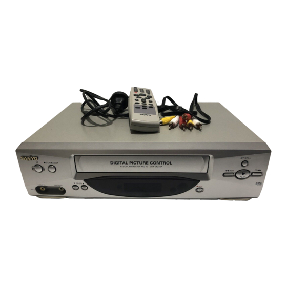
Page 9: Location Of Customer Controls
LOCATION OF CUSTOMER CONTROLS F R O N T (VHR-VK810A ONLY) 11. POWER 18. REC 12. STOP & TAPE EJECT 19. REMOTE CONTROL SENSOR 13. CASSETTE COMPARTMENT 10. VCR DISPLAY 14. REWIND 11. PROGRAM 15. PAUSE/STILL 12. AUDIO IN SOCKET 16. - Page 10 R E M O T E C O N T R O L 11. MARCHE 12. NUMBER BUTTONS 13. TV/VCR 14. BASIC OPERATION BUTTONS 15. CLEAR 16. A.TRACKING 17. CHILD LOCK 18. CM SKIP 19. EJECT 10. CURSORS( D E F G 11.
-
Page 11: Cabinet & Main Chassis
SECTION 2 CABINET & MAIN CHASSIS SERVICE METHOD Electrical Part (1) Re-assembly Flow for service like Fig. 2-1 Timer C.B.A Main C.B.A Housing & Deck Assembly (2) To check and replace Electrical parts Re-assemble the unit according to No.1) Re-assembly Flow. Place the unit like Fig. -
Page 12: Exploded Views
EXPLODED VIEWS 1. Cabinet and Main Frame Section NOTE) Refer to “SECTION 5 REPLACEMENT PARTS LIST” in order to look for the part number of each part. _ OPTIONAL PARTS... -
Page 13: Packing Accessory Section
2.Packing Accessory Section NOTE) Refer to “SECTION REPLACEMENT PARTS LIST NOTE) in order to look for the part number of each part. OPTIONAL PARTS CABLE SET ASS'Y (Optional parts) PLUG ASS'Y 1WAY (Optional parts) PLUG ASS'Y 2WAY (Optional parts) INSTRUCTION MANUAL BATTERY PACKING (LF) BAG. -
Page 14: Remote Control Section
3.Remote Control Section... -
Page 15: Electrical Adjustment Points Arrangement
SECTION 3 ELECTRICAL ELECTRICAL ADJUSTMENT POINTS ARRANGEMENT : Measurement point : Adjustment point RCA JACK Drum Connector Hi-Fi AVCP W5J5 SYSTEM NICAM Micom W5J4 H/SW PG.ADJ L/D IC E2PROM DISPLAY(DOT,CLK) SHUTTLE KEY-BOARD MAIN P.C.B (Component Side) -
Page 16: Electrical Adjustment Procedures
ELECTRICAL ADJUSTMENT PROCEDURES 1. Servo Adjustment 1) PG Adjustment • Test Equipment a) OSCILLOSCOPE b) PAL TEST TAPE (VHS SP) • Adjustment And Specification MODE MEASUREMENT POINT ADJUSTMENT POINT SPECIFICATION V.Out PLAY VR501 6.5 ± 0.5H H/SW(W5J4, W5J5) • Adjustment Procedure a) Insert the PAL SP Test Tape and play. -
Page 17: Electrical Troubleshooting Guide
ELECTRICAL TROUBLESHOOTING GUIDE 1. Power Circuit(SMPS) (1) No 5.3VA. No 5.3VA. Replace the F101 Is the F101 normal? (Use the same Fuse). Is the BD101 normal? Replace the BD101. Is the R101 normal? Replace the R101. Does the oscillation waveform appear at Is Vcc(about 13~15V) permittable at the the IC101 Pin 1? IC101 Pin 5? - Page 18 7. Power Circuit(SMPS) (2) No 12VA.(Capstan) No 12VA. Does 5.3VA work normally? Check whether 5.3VA is out of order. Is the D109 normal? Replace the D109. Check 12VA Line of the Main PCB short. (3) No 12VA (Hi-Fi, Buffer) No 12VA. Is Vcc(about 14VA) put into the Q155 Replace the Peripheral Circuitry of Q155.
- Page 19 7. Power Circuit(SMPS) (4) No 5VT(5V) No 5VT.(5V) Is 5.3VA put into the Q152(Q151) collector? Is the Q163(Q162) Base “H”? Check the µ-com Control. Is about 4.7V put into the Check the Q163(Q162) Q152(Q151) Base? whether it works normally. Check or Replace the Q152(Q151).
-
Page 20: Servo Circuit
2. Servo Circuit Unstable Video in PB Mode. Does the on screen noise level change periodically? Do CTL pulses appear at IC501 pin 37? Does the CFG divide Is the height of the CTL waveform appear at IC501 Head adjusted correctly? pin 40? Do the CTL pulses move Adjust the CTL Head. - Page 21 Drum Motor stopped. Does 12V appear at PMD01 Pin 4? Does 2.8V appear at PMD01 Pin 1? Check Power. Check Connector and Drum Motor Ass’y. Does Drum PWM appear at IC501 Pin 26? Check the Components and foil Pattern between IC501 Pin 26 and PMD01 Do DFG Pulses appear at PMD01 Pin 3? Pin 1 for shorts.
- Page 22 Capstan Motor Stopped. Does 12VA appear at PMD02 Pin 5? Does 2.8V appear at PMD02 Pin 4? Check Power. Check Connector and Capstan Does PWM wave appear at IC501 Motor Ass’y. Pin 25? Check the Components and foil Patterns Does the CFG signal appear at PMD02 Connected between IC501 Pin 25 and Pin 6? PMD02 Pin 4 for shorts.
-
Page 23: System & Front Panel Circuit
3. System & Front Panel Circuit Auto stop. Does SW30 waveform appear at IC501 Pin 24? Do Take-up reel pulses Check the Drum Motor appear at IC501 Pin 4? Signal. Do Take-up reel pulses Change IC501. appear at the base of Q514? Does 5.3V appear at RS501. - Page 24 Cassette tape loading is unstable. Is REG 12V applied to IC502 Pin 7? Is High signal applied to IC501 Pin 57 Check the power. when inserting the CST? Is 5.3V applied to R560? Does Low signal occur form IC501 Pin 19 Check the CST SW and Check the power.
-
Page 25: Y/C Circuit
4. Y/C CIRCUIT (1) No Video in EE Mode, No Video in EE Mode Check the Video Input Does the Video signal Jack. appear at the IC301 Pin 38? (Line In Jack) Is 5V applied to the IC301 Check the 5V Line. Pins 16, 40, 55, 58, 75, 87? (Power Circuit) Check the System Circuit. - Page 26 3. Y/C CIRCUIT (2) When the Y(Luminance) signal doesn’t appear on the screen in PB Mode, Is 5V applied to the IC301 Check the line of the 5.2V Line. (Power Circuit) Pins 16, 40, 55, 58, 87? Is the I C Bus siganl applied Refer to ‘SYSTEM I C BUS...
- Page 27 3. Y/C CIRCUIT (3) When the C(Color) signal doesn’t appear on the screen in PB Mode, Is 5V applied to the IC301 Check the line of the 5.2V Line. (Power Circuit) Pins 16, 40, 55, 58, 87? Is the Color Rotary signal Check the Color Rotary applied to the IC301 Circuit.
- Page 28 3. Y/C CIRCUIT (4) When the Video signal doesn’t appear on the screen in REC Mode, Is the EE signal normal? Check EE Mode. Is 5V applied to the IC301 Check the line of the 5.2V Pins 16, 40, 55, 58, 87? Line.(Power Circuit) Does PB Mdoe operate Check PB Mode.
-
Page 29: Tuner/If Circuit
5. Tuner/IF circuit (1) No picture on the TV screen No picture on the TV screen Does the Video signal at Is +30VT applied to Check 33VT line. the TU701 Pin24? TU701 Pin 16? Is +5VT applied to Check 5VT line. TU701 Pin 13? Does the Clock signal Check the liC Clock... - Page 30 (2) No sound (VHR-VK810A) No sound Check the Vcc of IC751 Pins 1, 19, 33. Check 5V power. Check the Tuner SiF signal at IC751 Pin 2. Check the Tuner Audio of TU701 Pin 22. Check the oscillator of IC751 Pins 5, 6. Replace X751.
- Page 31 (3) No sound (VHR-VK210A) No sound Check the Vcc of IC301 Pin 75. Check 5VT power. Check the Tuner Audio signal Chekc the signal flow from TU701 at IC301 Pin 76. Pin21 to IC301 Pin 76. Check the Audio signal at IC301 Pin 96.
-
Page 32: Hi-Fi Circuit
6. Hi-Fi Circuit (VHR-VK810A) Hi-Fi Playback. Check the Vcc of No sound IC801.(Pins 34, 40) Check the Hi-Fi Selection Check power. Switch and the Tape quality. Is the RF Envelope at Is the Head switching signal Check IC501 Pin 23. IC801 Pin 44 over 2Vp-p? IC802 Pin 41 O.K? (Audio head switch 25) - Page 33 Hi-Fi REC. It is impossible to record and playback Hi-Fi Audio signal. Check Vcc of IC801. (Pins 34,40) Check IC801 Pin 42(Data),Pin 43(CLOCK). Check Power. Do Audio signals appear at IC801 Check ports of µ-COM. Pins 16, 17? Do FM Audio signals appear at IC801 Check Audio input signal of IC801 Pin 36? Pins 2, 3(TU.A.), 6, 7(Scart 1)