Table of Contents
Advertisement
Quick Links
This manual contains text, diagrams and explanations which will guide the reader in the correct installation and
operation of the FX and FX
ing to install or use these units.
Further information can be found in the FX PROGRAMMING MANUAL, FX and FX0/FX
manuals.
When the FX
-485ADP is used with the FX
0N
USER'S GUIDE for operation.
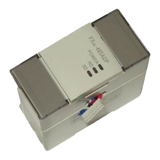
FX-485ADP COMMUNICATION ADAPTER
FX
0N
, 485 communication adapters. It should be read and understood before attempt-
0N
series programmable contoller, please see the FX
2N
-485ADP COMMUNICATION ADAPTER
USER'S GUIDE
JY992D53201C
series hardware
0N
-485-BD
2N
Advertisement
Table of Contents

Related Manuals for Mitsubishi Electric FX-485ADP


Summary of Contents for Mitsubishi Electric FX-485ADP
- Page 1 Further information can be found in the FX PROGRAMMING MANUAL, FX and FX0/FX manuals. When the FX -485ADP is used with the FX USER'S GUIDE for operation. FX-485ADP COMMUNICATION ADAPTER -485ADP COMMUNICATION ADAPTER USER'S GUIDE JY992D53201C series programmable contoller, please see the FX...
-
Page 2: External Dimensions
The adapter for FX-485ADP RS485 or the adapter for FX is designed to link the data between PC and computer by using 485PC-IF. (1)Data exchange by request from computer Specified data can be exchanged by sending a request command from the computer to the PC. Except for few functions (global function, on-demand function), the program for data link is not needed at the PC side. -
Page 3: System Configuration
1.2 System configuration The system configuration of computer and PC is either 1 : 1 or 1 : n, and for communication with the computer, the RS-485 or RS-422 is used. (1) Computer and PC by 1 : 1 configuration Computer 485PC-IF (2) Computer and PC by 1 : n configuration... -
Page 4: Connection With Pc
Ver. 1.20 or later Exclusive protocol format 1 and format 4 are supported. Ver. 3.30 or later Exclusive protocol format 1 and format 4 are supported. In the case of FX-485ADP WIRING Remarks M IT S U B IS H I... - Page 5 2.1 Examples of two-pair wiring (for RS-422 circuit) (1) When connecting one computer and one PC 485PC-IF Cable connection and signal direction Signal name LINK SG Grounding resistance of or less (2) Computer and PCs in 1 : n connection ( n has a maximum value of 16 ). The terminal lagout shown is diagrammatic only.
- Page 6 2.2 Examples of one-pair wiring (for RS-485 circuit) (1) When connecting one computer and one PC 485PC-IF Cable connection and signal direction Signal name LINK SG Grounding resistance of or less (2) Computer and PCs in 1 : n connection ( n has a maximum value of 16 ). The terminal lagout shown is diagrammatic only.
-
Page 7: Cautions For Wiring
2.3 Terminating resistances The terminating resistances are resistances connected between terminals SDA and SDB, and between terminals RDA and RDB at both end stations of the circuit (or the interface when an interface such as 485PC-IF is used at both end stations), when connecting with the RS-485 or RS-422 circuit. For connection examples, see section 2.1 and 2.2. -
Page 8: Environmental Specifications
Environmental specifications Operating ambient temperature 0 to 55°C, storage temperature -20 to 70°C Humidity no condensation 35 to 85% RH (No condensation) Conforming to JIS C 0911. 10 to 55 Hz, 0.5 mm (max. 2G), 2 hr each in 3 axes; however, 0.5G Vibration resistance when mounting DIN rail. -
Page 9: Device Range
COMMAND AND DEVICE RANGE 4.1 Computer commands Command Symbol ASCII code To read out on/off state of bit device in batch in the unit of 1 42H,52H point. To read out on/off state of bit device in batch in the unit of 16 points. - Page 10 In case of trouble, check the following points, and remedy according to the troubleshooting guide in the 485PC- IF manual. (1) Power LED : The extension cable is normally connected to the PC. Otherwise : The extension cable is not connected correctly, or external 24 V DC power supply is not func- tioning correctly.
-
Page 11: Start-Up Procedure
Prior to start of operation, follow the procedure below. As for detail of procedure, see the 485PC-IF manual. Determine system configuration Setting of transfer specification (D8120) • Specification of data length • Specification of parity • Specification of stop bit •... - Page 12 This manual has been written to be used by trained and competent personnel. This is defined by the European directives for machinery, low voltage and EMC. If in doubt at any stage during the installation of the FX-485ADP, FX professional electical engineer who is qualified and trained to the local and national standards. If in doubt about the operation or use of the FX-485ADP, FX Mitsubishi Electric distributor.