Table of Contents
Advertisement
Quick Links
SERVICE MANUAL
Ver 1.0 2001.10
Recording time
NW-E7: Approx. 60 min. (132kbps)
Approx. 80 min. (105kbps)
Approx. 120 min. (66kbps)
NW-E10: Approx. 120min. (132kbps)
Approx. 160 min. (105kbps)
Approx. 240 min. (66kbps)
Sampling frequency response
44.1kHz
Recording format
ATRAC3
MP3; Bit rate*: 32–256 kbps
Sampling rate: 32/44.1/48 kHz
* Variable bit rate files are not supported. Bit rate
higher than 128 kbps is not guaranteed when
you select the sampling rate 32 or 48 kHz.
Frequency response
20 to 20,000 Hz (single signal measurement)
Output
Earphone: stereo mini-jack
Signal-to-noise ratio (S/N)
More than 80dB (excluding 66 kbps)
Dynamic range
More than 85dB (excluding 66 kbps)
Operating temperature
5°C to 35°C (-41°F to 95°F)
Sony Corporation
9-873-343-01
2001J0200-1
Personal Audio Company
© 2001.10
Service Manual Production Group
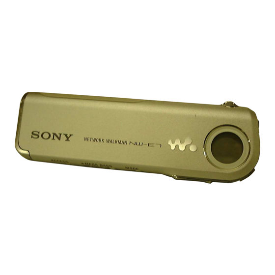
NW-E7/E10
Photo : NW-E7
SPECIFICATIONS
Power source
• DC IN 1.2V (internal nickel metal hydride battery)
• DC IN 4.5V (supplied AC power adaptor)
Battery life
Approx. 11 hours
Dimensions (approx.)
27.8 × 92.4 × 13.3mm (1
(w/h/d, projecting parts not included)
30.9 × 92.4 × 14.7mm (1
(including projecting parts)
Mass (approx.)
55g (1.9 oz) (battery included)
Memory capacity
NW-E7: 64MB (including the system software)
NW-E10: 128MB (including the system software)
Supplied accessories
USB cradle (1)
Earphones (1)
USB cable (1)
AC power adaptor (for the supplied USB cradle) (1)
Carrying pouch (1)
CD-ROM (OpenMG Jukebox installation disc) (1)
NW-E7/E10 Operating Instructions (1)
OpenMG Jukebox Operating Instructions (1)
Design and specifications are subject to change without notice.
AEP Model
UK Model
E Model
× 3
×
1
3
17
/
/
/
inches)
8
4
32
× 3
×
1
/
3
/
19
/
inches)
4
4
32
NETWORK WALKMAN
NW-E7/E10
NW-E7
Advertisement
Table of Contents

Related Manuals for Sony NW-E7


Summary of Contents for Sony NW-E7
-
Page 1: Specifications
55g (1.9 oz) (battery included) Memory capacity Sampling rate: 32/44.1/48 kHz * Variable bit rate files are not supported. Bit rate NW-E7: 64MB (including the system software) higher than 128 kbps is not guaranteed when NW-E10: 128MB (including the system software) Supplied accessories you select the sampling rate 32 or 48 kHz. -
Page 2: Table Of Contents
NW-E7/E10 TABLE OF CONTENTS SECTION 1 SERVICING NOTE Specifications ................1 UNLEADED SOLDER 1. SERVICING NOTE ............2 Boards requiring use of unleaded solder are printed with the lead-free mark (LF) indicating the solder contains no lead. 2. GENERAL ................3 (Caution: Some printed circuit boards may not come printed with the lead free mark due to their particular size.) -
Page 3: General
NW-E7/E10 SECTION 2 GENERAL This section is extracted from instruction manual. LOCATION AND FUNCTION OF CONTROLS (front) (rear) 1 i (Headphones/earphones) jack 2 Display 3 PLAY MODE button 4 Jog lever 5 VOLUME+/– button 6 MEGA BASS/AVLS button 7 Access lamp... -
Page 4: Basic Operations
Windows Explorer. software and NW-E7/E10 driver from the supplied CD-ROM to your computer. If you have already installed "OpenMG Jukebox" software, you also need to install NW-E7/E10 driver before connecting the player to your computer. -
Page 5: Disassembly
NW-E7/E10 SECTION 3 DISASSEMBLY The equipment can be removed using the following procedure. Case Battery, nickel hydrogen Main board Note : Follow the disassembly procedure in the numerical order given. 3-1. CASE Control ornamental plate 1 Screw Protector 5 Claws... -
Page 6: Main Board
NW-E7/E10 3-2. BATTERY, NICKEL HYDROGEN Lid case ASSY 1 Screw Battery, nickel hydrogen 3-3. MAIN BOARD 5 Screw Main board 6 Claws CN902 Switch flexible board 6 Claw 2 Claw 4 Peel off from frame Frame... -
Page 7: Diagrams
SECTION 4 NW-E7/E10 DIAGRAMS 4-1. BLOCK DIAGRAMS CN901 STATUS/ (1/2) CONTROL D– D– PROTOCOL APPLICATION TRANSCEIVER ENGINE SWITCH INTERFACE INTR Q901 RESET D903 END POINT FIFO/ CONNECTOR 256M BIT FLASH ROM (E7) DPLL 8 BYTE SET-UP REGISTER SIGNAL PATH 512M BIT FLASH ROM (E10) XOUT AD0 –... -
Page 8: Printed Wiring Boards (Main Section)
NW-E7/E10 4-2. PRINTED WIRING BOARDS – MAIN SECTION – : Uses unleaded solder. Semiconductor Location Ref. No. Location Ref. No. Location D101 IC604 RECHAGEABLE BATTERY D201 IC701 NICKEL HYDROGEN D401 IC801 1PC, 1.2V D402 IC802 D403 IC803 MAIN BOARD (SIDE B) -
Page 9: Schematic Diagram (Main Section (1/2))
NW-E7/E10 4-3. SCHEMATIC DIAGRAM – MAIN SECTION (1/2) – See page 11 for Notes. See page 11 for IC Block Diagrams. See page 11 for Waveforms. -
Page 10: Schematic Diagram (Main Section (2/2))
NW-E7/E10 4-4. SCHEMATIC DIAGRAM – MAIN SECTION (2/2) – See page 11 for Notes. See page 11 for IC Block Diagrams. See page 11 for Waveforms. - Page 11 NW-E7/E10 Note on Schematic Diagram: Waveforms • All capacitors are in µF unless otherwise noted. pF: µµF 50 WV or less are not indicated except for electrolytics and tantalums. • All resistors are in Ω and W or less unless otherwise specified.
- Page 12 NW-E7/E10 IC901 ML60851CTB DACK PROTOCOL END POINT F1F0/ TRANSCEIVER ENGINE 8 BYTE SETUP REGISTER D– APPLICATION INTERFACE VCC3 TEST1 TEST2 STATUS/ OSCILLATOR CONTROL XOUT RESET ADSEL IC701 SM8142BD-EL HIGH VOLTAGE SWITCHING CIRCUIT DIVIDING CIRCUIT DIVIDING CIRCUIT OSCILLATOR FOR BOOSTING VOLTAGE AND EL DRIVE...
-
Page 13: Exploded View
NW-E7/E10 SECTION 5 EXPLODED VIEWS • Accessories are given in the last of this NOTE : • Items marked “ * ”are not stocked since they parts list. are seldom required for routine service. Some • -XX, -X mean standardized parts, so they may •... -
Page 14: Case Section
NW-E7/E10 5-2. CASE SECTION not supplied not supplied not supplied Ref. No. Part No. Description Remark Ref. No. Part No. Description Remark 3-233-056-01 SHEET (WINDOW), ADHESIVE * 51 3-234-481-01 SHEET (MODE), ADHESIVE * 52 3-233-060-01 BUTTON (MODE) 3-343-254-71 SCREW B1.7x3.5... -
Page 15: Electrical Parts List
NW-E7/E10 SECTION 6 MAIN ELECTRICAL PARTS LIST NOTE : • Due to standardization, replacements in the • SEMICONDUCTORS In each case, u : µ , for example : The components identified by mark ! or dotted parts list may be different from the parts line with mark ! are critical for safety. - Page 16 NW-E7/E10 MAIN Ref. No. Part No. Description Remark Ref. No. Part No. Description Remark <CONNECTOR> <INDUCTOR> CN601 1-794-743-21 CONNECTOR, FFC(LIF(NON-ZIF)) L101 1-469-424-21 INDUCTOR 47uH CN901 1-815-777-21 CONNECTOR, FPC(ZIF) 10P L201 1-469-424-21 INDUCTOR 47uH L301 1-414-373-31 INDUCTOR 10uH <DIODE> L401 1-424-872-21 INDUCTOR...
- Page 17 NW-E7/E10 MAIN Ref. No. Part No. Description Remark Ref. No. Part No. Description Remark R409 1-218-965-11 RES-CHIP 1/16W R817 1-218-977-11 RES-CHIP 100K 1/16W R410 1-218-965-11 RES-CHIP 1/16W R818 1-218-977-11 RES-CHIP 100K 1/16W R411 1-218-953-11 RES-CHIP 1/16W R819 1-218-941-11 RES-CHIP 1/16W...
- Page 18 NW-E7/E10 Ref. No. Part No. Description Remark X802 1-795-313-21 VIBRATOR, CERAM (8MHz) ACCESSORIES X901 1-781-620-21 VIBRATOR, CERAM (48MHz) ************ ************************************************************ 1-418-261-12 ADAPTOR, AC (AC-E455F) (FR,E33) MISCELLANEOUS 1-473-115-11 ADAPTOR, AC (AC-E455F) (UK,HK) 1-476-905-11 CRADLE UNIT(NWA-UC7) *************** 1-757-412-31 USB CABLE 1-756-226-11 BATTERY, NICKEL HYDROGEN...
- Page 19 NW-E7/E10...
- Page 20 NW-E7/E10 REVISION HISTORY Clicking the version allows you to jump to the revised page. Also, clicking the version at the upper right on the revised page allows you to jump to the next revised page. Ver. Date Description of Revision...