Table of Contents
Advertisement
SAFETY PRECAUTION FOR SERVICE MANUAL ........................................................................................................... 2
IMPORTANT SERVICE NOTES (FOR UK ONLY) ............................................................................................................ 3
SPECIFICATIONS ............................................................................................................................................................. 3
NAMES OF PARTS ........................................................................................................................................................... 4
OPERATION MANUAL ...................................................................................................................................................... 6
DISASSEMBLY .................................................................................................................................................................. 7
REMOVING AND REINSTALLING THE MAIN PARTS ..................................................................................................... 9
ADJUSTMENT .................................................................................................................................................................. 10
NOTES ON SCHEMATIC DIAGRAM ............................................................................................................................... 12
BLOCK DIAGRAM ............................................................................................................................................................ 13
SCHEMATIC DIAGRAM / WIRING SIDE OF P.W.BOARD .............................................................................................. 16
WAVEFORMS OF CD CIRCUIT ....................................................................................................................................... 30
TROUBLESHOOTING (CD CHANGER CONTROL / CD SECTION) ............................................................................... 31
FUNCTION TABLE OF IC ................................................................................................................................................ 35
FL DISPLAY ...................................................................................................................................................................... 41
WIRING OF PRIMARILY SUPPLY LEADS (FOR UK ONLY) ......................................................................................... 41
REPLACEMENT PARTS LIST/EXPLODED VIEW
SERVICE MANUAL
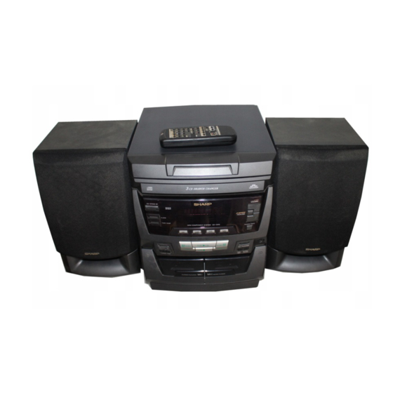
CD-C410H and CP-C410 constitute CD-C410H.
• In the interests of user-safety the set should be restored to its
• Note for users in UK
CONTENTS
SHARP CORPORATION
- 1 -
CD-C410H
CP-C410
original condition and only parts identical to those specified be
used.
Recording and playback of any material may require consent
which SHARP is unable to give. Please refer particularly to the
provisions of Copyright Act 1956, the Dramatic and Musical
Performers Protection Act 1956, the Performers Protection Acts
1963 and 1972 and to any subsequent statutory enactments and
orders.
CD-C410H,CP-C410
No. S5728CDC410H/
Page
Advertisement
Table of Contents

Related Manuals for Sharp CD-C410H


Summary of Contents for Sharp CD-C410H
-
Page 1: Table Of Contents
• Note for users in UK Recording and playback of any material may require consent which SHARP is unable to give. Please refer particularly to the provisions of Copyright Act 1956, the Dramatic and Musical Performers Protection Act 1956, the Performers Protection Acts 1963 and 1972 and to any subsequent statutory enactments and orders. -
Page 2: Safety Precaution For Service Manual
CD-C410H,CP-C410 (Except for UK) SAFETY PRECAUTION FOR SERVICE MANUAL Precaution to be taken when replacing and servicing the Laser Pickup. The AEL (Accessible Emission Level) of Laser Power Output for this model is specified to be lower than Class I Requirements. -
Page 3: Important Service Notes (For Uk Only)
CD-C410H,CP-C410 FOR A COMPLETE DESCRIPTION OF THE OPERATION OF THIS UNIT, PLEASE REFER TO THE OPERATION MANUAL. IMPORTANT SERVICE NOTES (FOR UK ONLY) WITHSTANDING Before returning the unit to the customer after completion of a VOLTAGE TESTER repair or adjustment it is necessary for the following withstand... -
Page 4: Names Of Parts
CD-C410H,CP-C410 NAMES OF PARTS CD-C410H Front Panel 1. Disc Tray 2. Disc Number Indicator 3. Timer Indicator 3 4 5 4. Record Indicator 5. Sleep Indicator 6. Extra Bass Indicator: X-BASS SLEEP X-BASS 7. Function/CD Track/CD Counter/Frequency/Preset Channel/Volume/Timer/Sleep Time Indicator 8 9 10 8. - Page 5 CD-C410H,CP-C410 CD-C410H Rear Panel 1. Video/Auxiliary (Audio Signal) Input Sockets 2. Speaker Terminals 3. AC Power Lead 4. FM 75 ohms Aerial Socket 5. AM Loop Aerial Input Socket CP-C410 Speaker Section 6. Full Range Speaker 7. Bass Reflex Duct 8.
-
Page 6: Operation Manual
CD-C410H,CP-C410 OPERATION MANUAL – 6 –... -
Page 7: Disassembly
CD-C410H,CP-C410 DISASSEMBLY CP-C410H Caution on Disassembly Follow the below-mentioned notes when disassembling Top Cabinet the unit and reassembling it, to keep it safe and ensure ( A1 ) x2 excellent performance: ø3 x12mm 1. Take cassette tape and compact disc out of the unit. - Page 8 CD-C410H,CP-C410 Display PWB ( K1 ) x4 Front Panel ø3 x12mm ( E1 ) x9 ( L1 ) x1 ø3 x10mm ø2.6 x10mm ( E1 ) x1 ø3 x10mm Shift Lever ( E2 ) x2 CD Changer Mechanism Tape ( E1 ) x1 Mechanism ø3 x8mm...
-
Page 9: Removing And Reinstalling The Main Parts
CD-C410H,CP-C410 REMOVING AND REINSTALLING THE MAIN PARTS CD MECHANISM SECTION Perform steps 1, 2, 3, 10 and 11 of the disassembly method Loading Motor to remove the CD mechanism. How to remove the loading motor (See Fig. 9-1) 1. Remove the screws (A1) x 2 pcs., to remove the loading motor. -
Page 10: Adjustment
CD-C410H,CP-C410 ADJUSTMENT TUNER SECTION MECHANISM SECTION • Driving Force Check fL: Low-range frequency fH: High-renge frequency Torque Meter Specified Value • AM IF/RF Play: TW-2412 Tape 1: Over 80 g Signal generator: 400 Hz, 30%, AM modulated Tape 2: Over 80 g... -
Page 11: Test Mode
CD-C410H,CP-C410 TEST MODE • Setting the test mode Any one of test mode can be set by pressing several keys as follows. <REC. PAUSE> + <DISC. SKIP> + <POWER> TEST: CD operation test • TEST mode Function — CD test mode Setting of TEST mode Indication of CD TST mode (Fig. -
Page 12: Notes On Schematic Diagram
CD-C410H,CP-C410 NOTES ON SCHEMATIC DIAGRAM • The indicated voltage in each section is the one measured • Resistor: by Digital Multimeter between such a section and the chas- To differentiate the units of resistors, such symbol as K and sis with no signal given. -
Page 13: Block Diagram
CD-C410H,CP-C410 Figure 13 BLOCK DIAGRAM (1/3) – 13 –... - Page 14 CD-C410H,CP-C410 SO301 FM IF AM IF FE301 ANTENNA CF301 Q301 CF302 L354 TERMINAL FM FRONT END T351 MONO/ST FM IF IN IC303 VR351 L-CH LA1832 FM MUTE LEVEL R-CH FM IF DET./FM MPX./AM IF AM LOOP ANTENNA MUTING FM OSC...
- Page 15 CD-C410H,CP-C410 UNSWITCH FL701 DISPLAY MEMORY BACK UP MONO/ST 31 32 TO CD SECTION TO CD SECTION Q701 TO POWER SECTION L-CH R-CH M IF PHM1 MUTING Q353 Q354 SW701 AVDD SW725 IC701 AVREF IX0191AW XL702 SYSTEM CONTROL TAGE 4.19MHz ATER...
-
Page 16: Schematic Diagram / Wiring Side Of P.w.board
CD-C410H,CP-C410 P19 7 - H TO MOTOR PWB CNS10 SW717 POWER 10 9 8 7 6 5 4 3 2 1 SW718 10 15 CLOCK R769 CNP10 R765 SW715 TIMER/SLEEP TUN-DOWN SW719 SW721 MEMORY/SET P18 2 - A B C E... - Page 17 CD-C410H,CP-C410 P18 6 - H P18 5 - D P18 5 - D TO CD MOTOR TO PICKUP UNIT TO PICKUP UNIT CNS3A CNS2A CNS1A MAIN PWB-A1 6 5 4 3 2 CNP3 5 4 3 2 D404 D403 CNP1...
- Page 18 CD-C410H,CP-C410 P16 1 - C TO DISPLAY PWB PICKUP UNIT CNSM1 COLOR TABLE BROWN RD(R) ORANGE YELLOW GREEN BLUE VIOLET GRAY WH(W) WHITE BLACK PINK CNS1B 1 2 3 4 5 1 2 3 4 5 6 7 8 CNS2B...
- Page 19 CD-C410H,CP-C410 TUNER PWB-B1 POWER PWB-B2 F963 T1.6A L 250V CNS901 F962 T2.5A L 250V TO MAIN PWB CNP901 P17 11 - G T961 POWER TRANSFOMER Q354 E C B Q353 R367 E C B C374 C372 C371 C395 R359 C373...
- Page 20 CD-C410H,CP-C410 47/10 KTA1266 GR 0.47/50 1.5V 0.01 0.01 1/50 3.3V 64 63 61 60 55 54 53 52 51 50 49 CNS1B CNS1A CNP1 – FIN2 – – FIN1 EFBAL – – – FOSTA – DGND TOSTA – 2FREQ 0.1/50 –...
- Page 21 CD-C410H,CP-C410 MAIN PWB-A1 (1/4) 0.01 64 63 62 61 60 59 58 57 56 55 54 53 52 51 50 EFLG µ-COM SUB-CODE SBSY INTERFACE DEF1 XVSS 3.3M 0.033 X-TAL XOUT 2KX8 GENERATOR 0.047 VVSS XVDD 0.022 ISET MUTER 5.6K 0.047...
- Page 22 CD-C410H,CP-C410 C702 FL701 220/6.3 25 26 27 28 29 30 31 32 33 Q701 KRC107 M –24.8V 4.4V –24.9V R734 R751 R701 100K 100K R750 100K R733 R738 KEY-3 KEY-2 R740 KEY-1 SET UP R797 AVDD IC701 AVREF SRS ON/OFF...
-
Page 23: Tape Mechanism
CD-C410H,CP-C410 DISPLAY PWB-A2 R741 R734 R751 R757 100K 100K R763 R767 R773 R777 R782 1.2K 1.8K 2.2K 3.9K R750 100K SW701 SW702 SW703 SW704 SW705 SW706 R756 RANDOM VOLUME X-BASS VOLUME OPEN DISK 100K /DEMO DOWN /CLOSE SKIP R764 R768... - Page 24 CD-C410H,CP-C410 OUT_R OUT_R CD_R C410 0.047 P21 12 - C A_GND (ML) TO CD SECTION C402 CD_L 0.047 R480 (ML) 100K R422 C434 R420 0.0027 C436 22/16 C404 RVref C403 0.047(ML) 0.047(ML) RINVIN2 C438 R418 100P RTOUT C440 RVRIN C442...
- Page 25 CD-C410H,CP-C410 R477 OUT_R 2.7K MAIN_L P26 1 - B A_GND MAIN_R TO POWER SECTION R478 2.7K R480 100K C434 0027 C436 22/16 C438 100P C440 C442 10/16 1/50 TUN_R C443 TUN_L 22/16 D402 A_GND 1SS119 TO TUNER PWB A–12V C444...
- Page 26 CD-C410H,CP-C410 MAIN PWB-A1 (3/4) – IC801 LA4451 – POWER AMP. 9 8 7 6 5 4 3 2 1 14 13 12 11 10 C829 C855 47/50 560P TO CD G C809 1000/25 C805 1/50 MAIN_L R805 A_GND C810 1000/25...
- Page 27 CD-C410H,CP-C410 L_CHECK ER AMP. P23 9 - G R_CHECK TO MAIN SECTION C453 C454 1/50 1/50 C855 560P TO CD GND 0/25 FM SIGNAL J801 R812 R835 HEADPHONES 330(1/2W) (1/2) R811 R836 (1/2) C811 (1/2W) C844 L832 L831 C843 (ML)
- Page 28 CD-C410H,CP-C410 • NOTES ON SCHEMATIC DIAGRAM can be found on page 12. Figure 28 SCHEMATIC DIAGRAM (9/10) – 28 –...
- Page 29 CD-C410H,CP-C410 IC401 IC701 IC302 NO. VOLTAGE NO. VOLTAGE NO. VOLTAGE NO. VOLTAGE NO. VOLTAGE NO. VOLTAGE NO. VOLTAGE –24.7V 0.41V 1.2V(1.2V) –24.7V 0V(0V) 2.1V –24.7V 0V(0V) –24.7V 4.4V 2.1V 4.6V(4.6V) –24.7V 1.8V 0V(0V) –24.7V 4.4V 2.2V 4.5V(4.5V) –24.7V 4.4V 2.2V 0.4V(11.3V)
-
Page 30: Waveforms Of Cd Circuit
CD-C410H,CP-C410 WAVEFORMS OF CD CIRCUIT STOP PLAY FOCUS SERCH 0.5ms 0.50 V 10.0 V IC1 20 F.E 0.5ms 10.0 V 0.5ms 5.0 V 0.50 V IC1 54 DRF 0.5ms 1.00 V PLAY 0.5ms 1.00 V NORMAL DISC TN0=01 20ms 1.00 V 0.5ms... -
Page 31: Troubleshooting (Cd Changer Control / Cd Section)
CD-C410H,CP-C410 TROUBLESHOOTING (CD SECTION) When the CD does not function When the CD section does not operate When the objective lens of the optical pickup is dirty,this section may not operate.Clean the objective lens,and check the playback operation.When this section does not operate even after the above step is taken,check the following items. - Page 32 CD-C410H,CP-C410 • When the CD tray fails to open or close. Check the OPEN CLOSE SW and the wiring from the IC701 Is there following voltage input in specific state of IC701 pin 19? pin 19 to the OPEN CLOSE SW.
- Page 33 CD-C410H,CP-C410 • Playback can only be performed when a disc is loaded. Check the laser diode driver. Is the Focus servo active? (Can you hear it working?) Check the area around IC1(16) - (21) (focus servo circuit). If the disc is not turning, the DRF Does the DRF signal change from "L"...
- Page 34 CD-C410H,CP-C410 • Checking the spin system. Play operation is performed without disc. The turntable rotates a little. The spin driver circuit is normal. Check the periphery of IC1 pins 23 to 27, pin 39, and pin 40, IC2 The turntable fails to rotate or rotates at high speed.
-
Page 35: Function Table Of Ic
CD-C410H,CP-C410 FUNCTION TABLE OF IC IC2 VHiLC78622U-1:Servo/Signal Control(LC78622U) (1/2) Terminal Name Input/Output Function Pin No. DEFI Input Input terminal of defect detection signal (DEF). (Connected to OV when not used.) Input For PLL Input terminal for test. Pull-down resistor is integrated. Surely connected to 0V. - Page 36 CD-C410H,CP-C410 IC2 VHiLC78622U-1:Servo/Signal Control(LC78622U) (2/2) Terminal Name Input/Output Pin No. Function Output Output terminal of subcodes P, A, R, S, T, U and W. SFSY Output Output terminal of synchronous signal of subcode frame. It drops when subcode stands by.
- Page 37 CD-C410H,CP-C410 IC1 VHiLA9240M/-1:Servo Amp.,(LA9240M) (1/2) Function Port Name Pin No. FIN2 Connection pin for photodiode of pickup. RF signal is generated through addition with FIN pin, and FE signal is generated through subtraction. FIN1 Connection pin for photodiode of pickup.
- Page 38 CD-C410H,CP-C410 IC1 VHiLA9240M/-1:Servo Amp.,(LA9240M) (2/2) Function Port Name Pin No. Micro computer command clock input pin. Micro computer command data input pin. Micro computer command chip enable input pin. (DETECT RF) RF level detection output. (Focus Serch Select) Pin to switch focus search mode. (± search/+ search for reference voltage) VCC2 VCC pin for servo system and digital system.
- Page 39 CD-C410H,CP-C410 IC701 RH-iX0191AWZZ:System Microcomputer (IX0191AW) (1/2) Function Pin No. Port Name Terminal Name Input/Output FIP6-0 FL DRIVER Output Segment Output — Connect with BACK UP VDD TAPE BIAS Output TAPE BIAS ON: H TAPE REC Output TAPE REC. ON:L T1/T2...
- Page 40 CD-C410H,CP-C410 IC701 RH-iX0191AWZZ:System Microcomputer (IX0191AW) (2/2) Pin No. Port Name Terminal Name Input/Output Function P124 TAPE1 RUN PULSE Input TAPE1 Run pluse P123 TAPE MECHA STOP Input Tape mecha up state: L 58*-60* P122-P120 DISC1-DISC3 Output Non connect 61-70 FIP25-16...
-
Page 41: Fl Display
CD-C410H,CP-C410 IC5 VHiM56748FP-1:Focus/Tracking/Spin/Slide Driver (M56748FP) Figure 41-1 BLOCK DIAGRAM OF IC LCD701 : VVKFiP9EM7R-1 FL Display MEMORY SLEEP X-BASS WIDE DOLBY Figure 41-2 FL DISPLAY WIRING OF PRIMARILY SUPPLY LEADS (FOR UK ONLY) If any one of the bands shown in Fig. 41-3 is removed for some reason, be sure replace it to the original position and same appearance as before. - Page 42 CD-C410H,CP-C410 — M E M O — – 42 –...
-
Page 43: Parts Guide
“HOW TO ORDER REPLACEMENT PARTS” To have your order filled promptly and correctly, please furnish the For U.S.A. only following information. Contact your nearest SHARP Parts Distributor to order. 1. MODEL NUMBER 2. REF. No. 3. PART NO. 4. DESCRIPTION For location of SHARP Parts Distributor, Please call Toll-Free;... - Page 44 CD-C410H,CP-C410 PRICE PRICE PART CODE DESCRIPTION PARTS CODE DESCRIPTION RANK RANK TRANSFORMERS CD-C410H INTEGRATED CIRCUITS T302 RCILZ0014AWZZ AL AM Antenna T351 RCILI0011AWZZ AD AM IF T961 RTRNP0118AWZZ J AW Power VHILA9240M/-1 AV Servo Amp.,LA9240M VHILC78622U-1 AT Servo/Signal Control,LC78622U COILS VHIM56748FP-1...
- Page 45 CD-C410H,CP-C410 PRICE PRICE DESCRIPTION PARTS CODE DESCRIPTION PART CODE RANK RANK AB 47 µF,16V,Electrolytic AA 0.0027 µF,16V RC-GZA476AF1C C433,434 VCTYMN1CX272K J AA 0.022 µF,25V AB 22 µF,16V,Electrolytic VCTYMN1EF223Z C435,436 RC-GZA226AF1C AA 0.001 µF,50V C94,95 VCKYMN1HB102K J C437,438 VCKYMN1HB101K J AA 100 pF,50V AA 0.001 µF,25V...
- Page 46 CD-C410H,CP-C410 PRICE PRICE PART CODE DESCRIPTION PARTS CODE DESCRIPTION RANK RANK VRD-MN2BD152J AA 1.5 kohms,1/8W R310 VRD-MN2BD472J AA 4.7 kohms,1/8W VRD-MN2BD823J AA 82 kohms,1/8W R315 VRD-MN2BD820J AA 82 ohms,1/8W VRD-ST2CD335J AA 3.3 Mohms,1/6W R318 VRD-MN2BD471J AA 470 ohms,1/8W VRD-MN2BD393J AA 39 kohms,1/8W...
- Page 47 CD-C410H,CP-C410 PRICE PRICE DESCRIPTION PARTS CODE DESCRIPTION PART CODE RANK RANK R771 VRD-MN2BD122J AA 1.2 kohms,1/8W SO801 QTANA0404AWZZ J AF Terminal,Speaker R772 VRD-MN2BD104J AA 100 kohm,1/8W SOLM1,2 RPLU-0002AWZZ AH Solenoid Ass’y R773~775 VRD-MN2BD182J AA 1.8 kohms,1/8W QSW-P0004AWZZ J AE Switch,Push Type [Open/Close]...
-
Page 48: Remote Control
CD-C410H,CP-C410 PRICE PRICE PART CODE DESCRIPTION PARTS CODE DESCRIPTION RANK RANK 92LM-EH1658A AG Head,Erase JKNBZ0333AWSA AC Knob,Operation B 92LM-REL1676B AB Cap,Supply Reel JKNBZ0337AWSB AD Knob,X-BASS 92LM-CSPR1676B J AA Spring,Supply Cap JKNBZ0336AWSA AC Knob,Open/Close,Rec./Playback 92LN-BAND1318A AA Nylon Band,80mm MLEVP0068AWZZ J AB Lever,Change 92LS2R6S1746A AA Screw,ø2.6×2.5mm... - Page 49 CD-C410H,CP-C410 PRICE PRICE DESCRIPTION PARTS CODE DESCRIPTION PART CODE RANK RANK TLABE0153AWZZ AB Label P.W.B. ASSEMBLY (Not Replacement Item) PWB-A1~3 92LPWB2529MANS J — Main/Display/Headphones (Combined Ass’y) PWB-B1~3 92LPWB2529TUNS J — Tuner/Power/Powe (Combined Ass’y) PWB-C QPWBF0106AWZZ J AF Tape Mechanism (PWB Only)
- Page 50 CD-C410H,CP-C410 CD-C410H 306-2 306-1 306-3 305x2 PWB-D Figure 7 CD MECHANISM EXPLODED VIEW – 7 – – 52 –...
- Page 51 CD-C410H,CP-C410 CD-C410H TAPE1 TAPE2 503x3 503x2 503x3 503x2 SOLM1 SWM5 501x2 SWM4 SWM3 502x2 PWB-C BELT CONNECTION MOTOR Figure 8 TAPE MECHANISM EXPLODED VIEW – 53 – – 8 –...
- Page 52 CD-C410H,CP-C410 CD-C410H 619x7 PWB-A1 601x9 209-1 606x2 PWB-A2 209-2 618x2 260x2 FL701 PWB-A3 PWB-B1 603x3 Silicon 201-3 603x2 Grease 603x2 601x6 201-1 201-2 TAPE 604x4 204-1 MECHANISM PWB-B2 264x2 606x2 201-2 210-1 204-2 PWB-B3 206-1 260x4 271x2 206-2 210-2 Figure 9 CABINET EXPLODED VIEW (1/2) –...
- Page 53 CD-C410H,CP-C410 CD-C410H 608x2 608x2 243x2 MECHANISM 609x2 612x4 PWB-E Figure 10 CABINET EXPLODED VIEW (2/2) – 10 – – 55 –...
- Page 54 CD-C410H,CP-C410 CP-C410 SP1,2 708x4 Woofer Black Figure 11 SPEAKER EXPLODED VIEW – 56 – – 11 –...
-
Page 55: Packing Method (For Uk Only)
CD-C410H,CP-C410 PACKING METHOD (FOR UK ONLY) Setting position of switches and knobs Tape Mechanism STOP CD-C410H CP-C410 1. Packing Add., Left/Right SPAKA0124AWZZ 1. Polyathylene Bag, Speaker 92L411-0064 2. Polyathylene Bag, Unit SPAKP0013AWZZ1 2. Packing Add.,Speaker (Top/Bottom) 92L412-0063 3. Packing Case SPAKC0505AWZZ 3. - Page 56 CD-C410H,CP-C410 A9705-4778NS•HA•M Printed in Europe Writer and Editor: Quality & Reliability Control Center of Audio-Visual Systems Group, Sharp Corp. SG • SK • STCL – 58 –...