
Related Manuals for Yamaha YZ125X1


Summary of Contents for Yamaha YZ125X1
- Page 1 2008 OWNER’S SERVICE MANUAL MANUEL D’ATELIER DU PROPRIETAIRE FAHRER- UND WARTUNGSHANDBUCH MANUALE DI SERVIZIO DEL PROPRIETARIO YZ125 ( X ) / X1 1C3-28199-33...
- Page 3 2008 OWNER’S SERVICE MANUAL YZ125(X)/X1 1C3-28199-33-E0...
- Page 5 YZ125 (X)/X1 OWNER'S SERVICE MANUAL ©2007 by Yamaha Motor Co., Ltd. 1st Edition, June 2007 All rights reserved. Any reprinting or unauthorized use without the written permission of Yamaha Motor Co., Ltd. is expressly prohibited. Printed in Japan...
-
Page 6: Important Notice
Always turn off the engine Congratulations on your purchase of damage to the machine. while refueling. Take care to a Yamaha YZ series. This model is not spill any gasoline on the the culmination of Yamaha's vast ex- engine or exhaust system. - Page 7 All of the procedures in this manual tion or maintenance of your machine, are organized in a sequential, step- please consult your Yamaha dealer. by-step format. The information has been complied to provide the me- This manual should be considered a...
- Page 8 der of the jobs in the exploded di- 4. A job instruction chart "4" accom- HOW TO READ DESCRIPTIONS agram. A number that is enclosed panies the exploded diagram, To help identify parts and clarify pro- by a circle indicates a disassem- providing the order of jobs, names cedure steps, there are exploded dia- bly step.
-
Page 9: Table Of Contents
TABLE OF CONTENTS GENERAL INFORMATION SPECIFICATIONS REGULAR INSPECTION AND ADJUSTMENTS ENGINE CHASSIS ELECTRICAL TUNING... -
Page 10: General Information
CONTENTS CHAPTER 1 CHAPTER 6 ENGINE ......3-5 CHASSIS ......3-8 GENERAL INFOR- ELECTRICAL ELECTRICAL ....3-18 MATION CHAPTER 4 ELECTRICAL COMPO- NENTS AND WIRING DIA- DESCRIPTION ....1-1 ENGINE GRAM .......6-1 MACHINE IGNITION SYSTEM...6-2 IDENTIFICATION ..... 1-2 INCLUDED PARTS ..1-2 SEAT, FUEL TANK AND CHAPTER 7 IMPORTANT... -
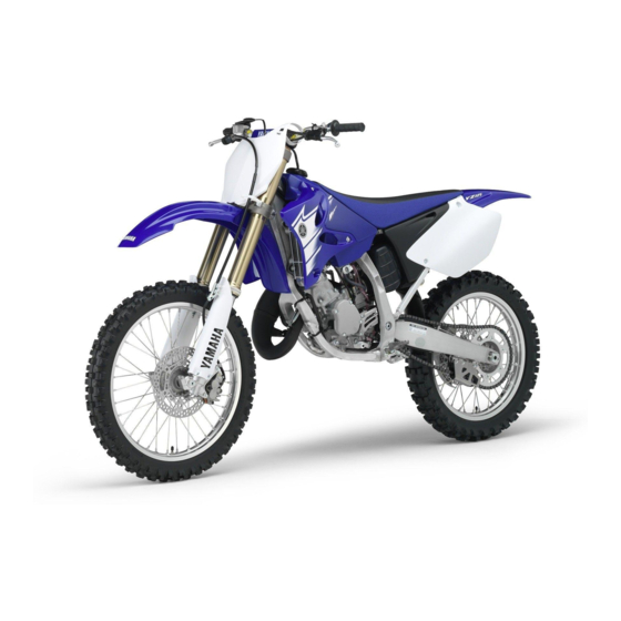
Page 11: Description
DESCRIPTION GENERAL INFORMATION DESCRIPTION Clutch lever 14. Fuel cock Engine stop switch 15. Air filter Front brake lever 16. Drive chain Throttle grip 17. Shift pedal Radiator cap 18. Starter knob Fuel tank cap 19. Front fork Kickstarter crank Fuel tank Radiator 10. -
Page 12: Identification
There are two significant reasons for knowing the serial number of your machine: 1. When ordering parts, you can give the number to your Yamaha dealer for positive identification of the model you own. VALVE JOINT 2. If your machine is stolen, the au- This valve joint "1"... -
Page 13: Checking Of Connec Tion
CHECKING OF CONNECTION ommended by Yamaha for carefully before reassembly. Al- shown. assembly and adjustment. ways replace piston pin clips after one use. Replace distorted cir- GASKETS, OIL SEALS AND O- clips. When installing a circlip "1", RINGS make sure that the sharp-edged 1. -
Page 14: Special Tools
SPECIAL TOOLS SPECIAL TOOLS The proper special tools are necessary for complete and accurate tune-up and assembly. Using the correct special tool will help prevent damage caused by the use of improper tools or improvised techniques. The shape and part number used for the special tool differ by country, so two types are provided. - Page 15 SPECIAL TOOLS Tool name/Part number How to use Illustration Fuel level gauge "1" This gauge is used to measure the YM-1312-A, 90890-01312 fuel level in the float chamber. Fuel level gauge adaptor "2" YM-01470, 90890-01470 Radiator cap tester These tools are used for checking YU-24460-01, 90890-01325 the cooling system.
-
Page 16: Ignition System
Dynamic spark tester This instrument is necessary for YM-34487 checking the ignition system compo- Ignition checker nents. 90890-06754 YAMAHA Bond No. 1215 (ThreeB- This sealant (Bond) is used for ® No. 1215) crankcase mating surface, etc. 90890-85505... -
Page 17: Control Functions
CONTROL FUNCTIONS CONTROL FUNCTIONS ENGINE STOP SWITCH The engine stop switch "1" is located on the left handlebar. Continue push- ing the engine stop switch till the en- gine comes to a stop. THROTTLE GRIP STARTER KNOB (CHOKE) The throttle grip "1" is located on the When cold, the engine requires a right handlebar;... - Page 18 STARTING AND BREAK-IN and avoid engine damage. • When any of the following parts Mixing oil: have been replaced, they must Recommended oil: BREAK-IN PROCEDURES be broken in. Yamalube "2-R" 1. Before starting the engine, fill the CYLINDER AND CRANKSHAFT: (Yamalube racing 2- fuel tank with a break-in oil-fuel About one hour of break-in oper-...
-
Page 19: Torque-Check Points
TORQUE-CHECK POINTS TORQUE-CHECK POINTS Frame construction Frame to rear frame Combined seat and fuel tank Fuel tank to frame Exhaust system Silencer to rear frame Engine mounting Frame to engine Engine bracket to engine Engine bracket to frame Steering Steering stem to handlebar Steering stem to frame Steering stem to upper bracket Upper bracket to handlebar... -
Page 20: Cleaning And Storage
CLEANING AND STORAGE CLEANING AND STORAGE the carburetor float bowl. 2. Remove the spark plug, pour a ta- CLEANING blespoon of SAE 10W-30 motor Frequent cleaning of your machine oil in the spark plug hole, and re- will enhance its appearance, maintain install the plug. -
Page 21: Specifications
GENERAL SPECIFICATIONS SPECIFICATIONS GENERAL SPECIFICATIONS Model name: YZ125X1 (USA, CDN) YZ125 (EUROPE, ZA) YZ125X (AUS, NZ) Model code number: 1C3D (USA, CDN) 1C3E (EUROPE) 1C3G (AUS, NZ, ZA) Dimensions: USA, AUS, NZ, ZA EUROPE, CDN Overall length 2,135 mm (84.1 in) 2,139 mm (84.2 in) -
Page 22: Maintenance Specifica Tions
MAINTENANCE SPECIFICATIONS Transmission type Constant mesh, 6-speed Operation Left foot operation Gear ratio: 31/13 (2.385) 29/15 (1.933) 27/17 (1.588) 23/17 (1.353) 24/20 (1.200) 23/21 (1.095) Chassis: USA, ZA, AUS, NZ EUROPE, CDN ← Frame type Semi double cradle Caster angle 25.5 °... -
Page 23: Maintenance Specifications
MAINTENANCE SPECIFICATIONS Item Standard Limit Out of round limit ---- 0.01 mm (0.0004 in) Piston: Piston size/ 53.957–53.972 mm (2.1243–2.1249 in) ---- Measuring point "H" 17.5 mm (0.69 in) ---- Piston clearance 0.040–0.045 mmm (0.0016–0.0018 in) 0.1 mm (0.004 Piston offset 0.5 mm (0.019 in)/EX-side ---- Piston pin:... - Page 24 MAINTENANCE SPECIFICATIONS Item Standard Limit Warp limit ---- 0.2 mm (0.008 Clutch spring free length 40.1 mm (1.579 in) 38.1 mm (1.500 in) Quantity ---- Clutch housing thrust clearance 0.15–0.26 mm (0.006–0.010 in) ---- Clutch housing radial clearance 0.014–0.046 mm (0.0006–0.0018 in) ---- Clutch release method Inner push, cam push...
- Page 25 MAINTENANCE SPECIFICATIONS Item Standard Limit Water pump: Type Single-suction centrifugal pump ---- CHASSIS Item Standard Limit Steering system: Steering bearing type Taper roller bearing ---- Front suspension: USA, CDN, ZA, AUS, EUROPE ← Front fork travel 300 mm (11.8 in) ---- ←...
- Page 26 Clutch lever free play (lever end) 8–13 mm (0.31–0.51 in) ---- Throttle grip free play 3–5 mm (0.12–0.20 in) ---- ELECTRICAL Item Standard Limit Ignition system: Ignition timing (B.T.D.C.) 0.48 mm (0.019 in) ---- Advancer type Electrical ---- CDI: Magneto-model (stator)/Manufacturer 1C3-10/YAMAHA ----...
-
Page 27: Tightening Torques
20 °C (68 °F) (Black-Green/ ---- Blue) Ω Pickup coil resistance (color) 248–372 at 20 °C (68 °F) (White/Blue- ---- White/Red) CDI unit-model/manufacturer 1C3-10/YAMAHA ---- Ignition coil: Model/manufacturer 1C3-00/YAMAHA ---- Minimum spark gap 6 mm (0.24 in) ---- Ω... - Page 28 TIGHTENING TORQUES Tightening torque Part to be tightened Thread size Q'ty m•kg ft•lb Throttle cable adjust bolt and locknut M8 × 1.25 Throttle cable M6 × 0.75 Crankcase M6 × 1.0 Right crankcase cover M6 × 1.0 Left crankcase cover M6 ×...
- Page 29 TIGHTENING TORQUES Tightening torque Part to be tightened Thread size Q'ty m•kg ft•lb Bleed screw (front fork) and base valve M5 × 0.8 △ Front fork and front fork protector M6 × 1.0 △ Cable guide (front brake hose) and lower bracket M6 ×...
- Page 30 TIGHTENING TORQUES Tightening torque Part to be tightened Thread size Q'ty m•kg ft•lb △ Rear shock absorber and frame M10 × 1.25 △ Rear shock absorber and relay arm M10 × 1.25 △ Rear frame and frame (upper) M8 × 1.25 △...
- Page 31 TIGHTENING TORQUES GENERAL TORQUE TORQUE SPECIFI- SPECIFICATIONS CATION (Bolt This chart specifies torque for stan- (Nut) dard fasteners with standard I.S.O. m•kg ft•lb pitch threads. Torque specifications 6 mm for special components or assem- blies are included in the applicable sections of this book.
-
Page 32: Cable Routing Diagram
CABLE ROUTING DIAGRAM CABLE ROUTING DIAGRAM "ENGINE STOP" button lead 10. YPVS breather hose Align the throttle cable locating Throttle cable 11. Engine bracket (right) tape with the cable guide. Clutch cable 12. Engine bracket (left) Pass the throttle cable, clutch Ground lead 13. - Page 33 CABLE ROUTING DIAGRAM Install the ignition coil, side core and ground lead together to the frame. Take care to fasten the ground lead so that its terminal is within the indicated range. Clamp the throttle cable and high tension cord to the frame. Clamp the clutch cable to the left engine bracket.
- Page 34 CABLE ROUTING DIAGRAM High tension cord 12. CDI unit stay Clamp to the frame the throttle "ENGINE STOP" button lead Pass the high tension cord to the cable, clutch cable, ignition coil Ignition coil lead left of the radiator hose. lead and "ENGINE STOP"...
- Page 35 CABLE ROUTING DIAGRAM Pass the CDI magneto lead and radiator breather hose between the frame and the radiator(right). Clamp the CDI magneto lead to the frame at its locating tape. Bring the connector cover into contact with the coupler. Locate the clamp ends in the ar- rowed range.
- Page 36 CABLE ROUTING DIAGRAM Master cylinder If the brake hose contacts the Brake hose holder spring (rear shock absorber), Brake hose correct its twist. Install the brake hose so that its Install the brake hose so that its pipe portion directs as shown pipe portion directs as shown and lightly touches the projec- and lightly touches the projec-...
- Page 37 CABLE ROUTING DIAGRAM Brake hose Install the brake hose so that its Pass the brake hose in front of Master cylinder pipe portion directs as shown the number plate and through "ENGINE STOP" button lead and lightly touches the projec- the cable guide.
-
Page 38: Regular Inspection And Adjustments
The following schedule is intended as a general guide to maintenance and lubrication. Bear in mind that such factors as weather, terrain, geographical location, and individual usage will alter the required maintenance and lubrication intervals. If you are a doubt as to what intervals to follow in maintaining and lubricating your machine, consult your Yamaha dealer. After... - Page 39 MAINTENANCE INTERVALS After Every Every Every As re- Item break- Remarks third fifth race quired CARBURETOR ● ● Inspect, adjust and clean SPARK PLUG ● ● Inspect and clean ● Replace DRIVE CHAIN Use chain lube. ● ● Lubricate, slack, alignment Chain slack: 48–58 mm (1.9–2.3 in) ●...
-
Page 40: Inspection And Mainte Nance
Check routing and connection ● ● Lubricate Yamaha cable lube or SAE 10W-30 motor oil PRE-OPERATION INSPECTION AND MAINTENANCE Before riding for break-in operation, practice or a race, make sure the machine is in good operating condition. Before using this machine, check the following points. - Page 41 PRE-OPERATION INSPECTION AND MAINTENANCE Item Routine Page Check for excessive wear and tire pressure. Check for loose Wheels P.3-15 spokes and have no excessive play. Check that the handlebar can be turned smoothly and have no ex- Steering P.3-15 – 16 cessive play.
-
Page 42: Engine
ENGINE ENGINE gine. 2. Remove: CHECKING THE COOLANT LEVEL • When coolant splashes to your • Coolant drain bolt "1" eye. Thoroughly wash your eye with Do not remove the radiator cap water and see your doctor. "1", drain bolt and hoses when the •... - Page 43 ENGINE 2. Apply the specified pressure. ADJUSTING THE CLUTCH CABLE ADJUSTING THE THROTTLE FREE PLAY CABLE FREE PLAY Radiator cap opening 1. Check: 1. Check: pressure: • Clutch lever free play "a" • Throttle grip free play "a" 95–125 kPa (0.95–1.25 →...
- Page 44 ENGINE • Do not twist the element when squeezing the element. • Leaving too much of solvent in the element may result in poor starting. 3. Inspect: 2. Apply: CHECKING THE TRANSMISSION • Air filter element • Lithium soap base grease OIL LEVEL →...
-
Page 45: Chassis
CHASSIS CHANGING THE TRANSMISSION of turns. The system has been disassem- bled. Pilot air screw: 1. Start the engine and warm it up • A brake hose has been loosened 2-1/4 turns out for several minutes and wait for or removed. five minute. - Page 46 CHASSIS Repeat steps (e) to (h) until of the c. Tighten the locknut. air bubbles have been removed Locknut: from the system. 5 Nm (0.5 m •kg, 3.6 ft•lb) If bleeding is difficult, it may be nec- essary to let the brake fluid system stabilize for a few hours.
- Page 47 CHASSIS e. Connect the transparent hose "5" to the bleed screw "6" and place the suitable container under its end. d. Remove the pad pin "6" and brake pads "7". 3. Inspect: • Brake fluid level Refer to "CHECKING THE f.
-
Page 48: Specifications
CHASSIS Tighten the pad pin "14". so that its top is in a horizontal po- sition. • While measuring the drive chain Pad pin: 2. Inspect: length, push down on the drive 18 Nm (1.8 m•kg, 13 • Brake fluid level chain to increase its tension. -
Page 49: Adjustments
CHASSIS clip to the direction as shown. b. Adjust the drive chain slack by • Protector turning the adjusters "3". • Dust seal "1" → To tighten Turn the adjuster "3" Use a thin screw driver, and be care- counterclockwise. ful not to damage the inner fork tube →... -
Page 50: Engine
CHASSIS By turning the adjuster "1". 4. Adjust: Extent of adjustment: • Spring preload → Stiffer "a" Increase the re- By turning the adjuster "2". bound damping force. (Turn Maximum Minimum → the adjuster "1" in.) Stiffer Increase the spring pre- →... -
Page 51: Chassis
CHASSIS • STANDARD POSITION: This is the position which is back by the specific number of clicks from the fully turned-in position. (Which align the punch mark "a" on the adjuster with the punch mark "b" on the high compression damping adjuster.) •... - Page 52 CHASSIS mark "b" on the adjuster body.) tice or a race check spokes for looseness. Standard position: About 1-1/2 turns out Do not force the adjuster past the minimum or maximum extent of adjustment. The adjuster may be 4. Adjust: damaged.
- Page 53 CHASSIS Steering ring nut (final tightening): 7 Nm (0.7 m•kg, 5.1 ft•lb) g. Check the steering stem by turn- ing it lock to lock. If there is any binding, remove the steering stem assembly and inspect the steer- ing bearings. h.
- Page 54 CHASSIS LUBRICATION To ensure smooth operation of all Use Yamaha cable lube or components, lubricate your machine equivalent on these areas. during setup, after break-in, and after Use SAE 10W-30 motor oil or every race. suitable chain lubricants. All control cable...
-
Page 55: Electrical
ELECTRICAL CHECKING THE IGNITION TIMING ELECTRICAL 7. Adjust: 1. Remove: • Ignition timing CHECKING THE SPARK PLUG • Fuel tank 1. Remove: Refer to "SEAT, FUEL TANK Adjustment steps: • Spark plug AND SIDE COVERS" section in a. Loosen the screws (stator) "1". 2. -
Page 56: Seat, Fuel Tank And Side Covers
SEAT, FUEL TANK AND SIDE COVERS ENGINE SEAT, FUEL TANK AND SIDE COVERS REMOVING THE SEAT, FUEL TANK AND SIDE COVERS 19 Nm (1.9 m kg, 13 ft lb) 7 Nm (0.7 m kg, 5.1 ft lb) 6 Nm (0.6 m kg, 4.3 ft lb) 7 Nm (0.7 m kg, 5.1 ft lb) 7 Nm (0.7 m kg, 5.1 ft lb) 7 Nm (0.7 m kg, 5.1 ft lb) - Page 57 SEAT, FUEL TANK AND SIDE COVERS REMOVING THE SIDE COVER 1. Remove: • Bolt (side cover) • Side cover (left and right) "1" Draw the side cover downward to re- move it because its claws "a" are in- serted in the air filter case. REMOVING THE NUMBER PLATE 1.
-
Page 58: Exhaust Pipe And Si Lencer
EXHAUST PIPE AND SILENCER EXHAUST PIPE AND SILENCER REMOVING THE EXHAUST PIPE AND SILENCER 12 Nm (1.2 m kg, 8.7 ft lb) 12 Nm (1.2 m kg, 8.7 ft lb) 10 Nm (1.0 m kg, 7.2 ft lb) 12 Nm (1.2 m kg, 8.7 ft lb) 12 Nm (1.2 m kg, 8.7 ft lb) Order Part name... -
Page 59: Exhaust Pipe And Silencer
• Fiber "2" 4. Install: • Inner pipe ® Fully apply Quick gasket (Yamaha bond No.1215) or equivalent as shown. Yamaha bond No.1215 ® (Three Bond No.1215): 90890-85505 5. Install: • Bolt (fiber) "1" Bolt (fiber): 10 Nm (1.0 m•kg, 7.2 ft•lb) -
Page 60: Radiator
RADIATOR RADIATOR REMOVING THE RADIATOR 2 Nm (0.2 m kg, 1.4 ft lb) 10 Nm (1.0 m kg, 7.2 ft lb) 10 Nm (1.0 m kg, 7.2 ft lb) 10 Nm (1.0 m kg, 7.2 ft lb) 2 Nm (0.2 m kg, 1.4 ft lb) Order Part name Q'ty... - Page 61 RADIATOR HANDLING NOTE • Washer "2" • Bolt (right radiator) "3" Bolt (right radiator): Do not remove the radiator cap 10 Nm (1.0 m•kg, 7.2 when the engine and radiator are ft•lb) hot. Scalding hot fluid and steam may be blown out under pressure, •...
-
Page 62: Carburetor And Reed Valve
CARBURETOR AND REED VALVE CARBURETOR AND REED VALVE REMOVING THE CARBURETOR AND REED VALVE 2 Nm (0.2 m kg, 1.4 ft lb) 2 Nm (0.2 m kg, 1.4 ft lb) 10 Nm (1.0 m kg, 7.2 ft lb) 1 Nm (0.1 m kg, 0.7 ft lb) Order Part name Q'ty... - Page 63 CARBURETOR AND REED VALVE DISASSEMBLING THE CARBURETOR 4 Nm (0.4 m kg, 2.9 ft lb) Order Part name Q'ty Remarks Mixing chamber top Refer to removal section. Throttle valve Needle holder Jet needle Float chamber Needle jet cover Float pin Float Valve seat Main jet...
- Page 64 CARBURETOR AND REED VALVE HANDLING NOTE CHECKING THE JET NEEDLE 1. Inspect: • Jet needle "1" Do not disassemble the venturi → Bends/wear Replace. block "1" and main nozzle "2" be- • Clip groove cause it will cause a drop in carbu- →...
- Page 65 CARBURETOR AND REED VALVE fuel level gauge. per/Replace valve stopper. Valve stopper height: Keep the carburetor and fuel level 8.2–8.6 mm (0.323– gauge vertically when measuring the 0.339 in) fuel level. e. If the fuel level is not within speci- fication, inspect the valve seat and needle valve.
- Page 66 CARBURETOR AND REED VALVE • After installing the needle valve to the float, install them to the carbure- tor. • Check the float for smooth move- ment. 2. Tighten: • Bolt (air filter joint) "1" Bolt (air filter joint): 2 Nm (0.2 m•kg, 1.4 ft•lb) •...
-
Page 67: Cylinder Head, Cylin Der And Piston
CYLINDER HEAD, CYLINDER AND PISTON CYLINDER HEAD, CYLINDER AND PISTON REMOVING THE CYLINDER HEAD AND CYLINDER 20 Nm (2.0 m kg, 14 ft lb) 28 Nm (2.8 m kg, 20 ft lb) 34 Nm (3.4 m kg, 24 ft lb) 13 Nm (1.3 m kg, 9.4 ft lb) 30 Nm (3.0 m kg, 22 ft lb) 4 Nm (0.4 m kg, 2.9 ft lb) - Page 68 CYLINDER HEAD, CYLINDER AND PISTON REMOVING THE PISTON AND POWER VALVE 4 Nm (0.4 m kg, 2.9 ft lb) 8 Nm (0.8 m kg, 5.8 ft lb) 4 Nm (0.4 m kg, 2.9 ft lb) 5 Nm (0.5 m kg, 3.6 ft lb) Order Part name Q'ty...
- Page 69 CYLINDER HEAD, CYLINDER AND PISTON REMOVING THE PUSH ROD 3. Remove: 1. Remove: • Piston ring "1" • Bolt (push rod) "1" • Push rod "2" Take care not to scratch the piston or damage the piston ring by expanding Set the collar "3"...
- Page 70 CYLINDER HEAD, CYLINDER AND PISTON 5. Check: • Free play Standard Wear limit There should be no noticeable free play. 54.000– → Cylin- Free play exists Inspect the 54.014 mm 54.1 mm der bore connecting rod for wear/Replace (2.1260– (2.130 in) "C"...
- Page 71 CYLINDER HEAD, CYLINDER AND PISTON 2. Check: CHECKING THE POWER VALVE • Piston mark "a" HOLE ON CYLINDER 1. Remove: Piston mark "a" Piston size • Carbon deposits (color) From power valve hole surface 53.957–53.960 "a". A (red) mm (2.1243– 2.1244 in) Do not use a sharp instrument.
- Page 72 CYLINDER HEAD, CYLINDER AND PISTON INSTALLING THE PISTON RING AND PISTON • When installing the piston pin 1. Install: clip, use the hand so that it may • Piston ring "1" not be distorted. • Do not allow the clip open ends •...
- Page 73 CYLINDER HEAD, CYLINDER AND PISTON Tighten the nuts in stage, using a Apply the lithium soap base grease crisscross pattern. on the O-rings. 4. Install: 7. Install: • Collar "1" • Cylinder head "1" • Push rod "2" • Copper washer "2" •...
-
Page 74: Clutch
CLUTCH CLUTCH REMOVING THE CLUTCH 10 Nm (1.0 m kg, 7.2 ft lb) 10 Nm (1.0 m kg, 7.2 ft lb) Order Part name Q'ty Remarks Refer to "CHANGING THE TRANSMISSION Drain the transmission oil. OIL" section in the CHAPTER 3. Bolt (brake pedal) Shift the brake pedal downward. - Page 75 CLUTCH REMOVING THE CLUTCH BOSS 80 Nm (8.0 m kg, 58 ft lb) Order Part name Q'ty Remarks Push rod 1 Circlip Washer Bearing Ball Push rod 2 Nut (clutch boss) Refer to removal section. Lock washer Refer to removal section. Clutch boss Refer to removal section.
- Page 76 CLUTCH → REMOVING THE CLUTCH BOSS CHECKING THE CLUTCH Wear/Damage Replace. 1. Remove: SPRINGS • Nut "1" 1. Measure: • Lock washer "2" • Clutch spring free length "a" → • Clutch boss "3" Out of specification Replace springs as a set. Straighten the lock washer tab and Clutch spring free use the clutch holding tool "4"...
- Page 77 CLUTCH friction plates and clutch plates. 2. Install: • Thrust washer [D=ø34 mm (1.34 in)] "1" • Clutch boss "2" 10. Install: • Dowel pin "1" 6. Install: • Gasket (clutch cover) "2" • Bearing "1" • Washer "2" 3. Install: •...
-
Page 78: Kick Shaft And Shift Shaft
KICK SHAFT AND SHIFT SHAFT KICK SHAFT AND SHIFT SHAFT REMOVING THE PRIMARY DRIVE GEAR Order Part name Q'ty Remarks Refer to "CHANGING THE TRANSMISSION Drain the transmission oil. OIL" section in the CHAPTER 3. Clutch cable Disconnect at engine side. Bolt (brake pedal) Shift the brake pedal downward. - Page 79 KICK SHAFT AND SHIFT SHAFT REMOVING THE KICK SHAFT AND SHIFT SHAFT Order Part name Q'ty Remarks Kick idle gear kick shaft assembly Refer to removal section. Shift pedal Shift shaft Roller Shift guide Refer to removal section. Shift lever assembly Refer to removal section.
- Page 80 KICK SHAFT AND SHIFT SHAFT REMOVING THE PRIMARY DRIVE GEAR 1. Loosen: • Bolt (primary drive gear) "1" Place an aluminum plate "a" between the teeth of the primary drive gear "2" and driven gear "3". CHECKING THE KICK GEAR AND CHECKING THE STOPPER LEVER KICK IDLE GEAR 1.
- Page 81 KICK SHAFT AND SHIFT SHAFT 4. Install: • Bolt (shift guide) "1" Bolt (shift guide): 10 Nm (1.0 m•kg, 7.2 ft•lb) 3. Install: • Kick shaft assembly "1" • Apply the transmission oil on the kick shaft. • Slide the kick shaft assembly into INSTALLING THE SHIFT SHAFT the crankcase, make sure the clip 1.
- Page 82 KICK SHAFT AND SHIFT SHAFT INSTALLING THE PRIMARY DRIVE GEAR 1. Install: • Spacer "1" • Primary drive gear "2" • Bolt "3" Install the primary drive gear with its 6. Install: depressed side toward you. • Bolt [crankcase cover (right)] "1" Bolt [crankcase cover (right)] : 10 Nm (1.0 m•kg, 7.2...
-
Page 83: Ypvs Governor
YPVS GOVERNOR YPVS GOVERNOR REMOVING THE YPVS GOVERNOR Order Part name Q'ty Remarks Refer to "KICK SHAFT AND SHIFT SHAFT" Right crankcase cover section. Governor assembly Dowel pin Refer to removal section. Retainer Ball Retainer weight Plain washer Thrust bearing Collar Plate Compression spring... - Page 84 YPVS GOVERNOR REMOVING THE GOVERNOR 1. Remove: • Dowel pin "1" While compressing the spring, re- move the dowel pin. CHECKING THE GOVERNOR GROOVE 2. Install: 1. Inspect: • Ball "1" • Washer "1" • Retainer "2" • Collar "2" To governor shaft "3".
-
Page 85: Water Pump
WATER PUMP WATER PUMP DISASSEMBLING THE WATER PUMP Order Part name Q'ty Remarks Refer to "KICK SHAFT AND SHIFT SHAFT" Crankcase cover (right) section. Water pump housing cover Impeller shaft gear Dowel pin Plain washer Impeller shaft assembly Bearing Refer to removal section. Oil seal Refer to removal section. - Page 86 WATER PUMP REMOVING THE OIL SEAL on the oil seal lip and impeller shaft. And install the shaft while turning it. • Replace the oil seal when transmis- sion oil or coolant leaks out from the water pump housing hole at the bot- tom.
- Page 87 WATER PUMP 4-32...
-
Page 88: Cdi Magneto
CDI MAGNETO CDI MAGNETO REMOVING THE CDI MAGNETO Order Part name Q'ty Remarks Refer to "SEAT, FUEL TANK AND SIDE Seat and fuel tank COVERS" section. Bolt (Radiator) Refer to "RADIATOR" section. Disconnect the CDI magneto lead. Left crankcase cover Nut (rotor) Refer to removal section. - Page 89 CDI MAGNETO REMOVING THE ROTOR INSTALLING THE CDI MAGNETO CHAPTER 3. 1. Remove: 1. Install: Ignition timing (B.T.D.C): • Nut (rotor) "1" • Stator "1" 0.48 mm (0.019 in) • Washer "2" • Screw (stator) "2" Use the rotor holding tool "3". 5.
-
Page 90: Engine Removal
ENGINE REMOVAL ENGINE REMOVAL REMOVING THE ENGINE 26 Nm (2.6 m kg, 19 ft lb) 34 Nm (3.4 m kg, 24 ft lb) 5 Nm (0.5 m kg, 3.6 ft lb) 64 Nm (6.4 m kg, 46 ft lb) 64 Nm (6.4 m kg, 46 ft lb) 85 Nm (8.5 m kg, 61 ft lb) 75 Nm (7.5 m kg, 54 ft lb) Order... - Page 91 ENGINE REMOVAL 26 Nm (2.6 m kg, 19 ft lb) 34 Nm (3.4 m kg, 24 ft lb) 5 Nm (0.5 m kg, 3.6 ft lb) 64 Nm (6.4 m kg, 46 ft lb) 64 Nm (6.4 m kg, 46 ft lb) 85 Nm (8.5 m kg, 61 ft lb) 75 Nm (7.5 m kg, 54 ft lb) Order...
- Page 92 ENGINE REMOVAL HANDLING NOTE • Spring "1" • Brake pedal "2" • O-ring "3" Support the machine securely so • Bolt (brake pedal) "4" there is no danger of it falling over. Bolt (brake pedal): 26 Nm (2.6 m•kg, 19 REMOVING THE DRIVE ft•lb) SPROCKET...
- Page 93 ENGINE REMOVAL • Screw (drive chain sprocket cov- er) "3" Screw (drive chain sprocket cover): 5 Nm (0.5 m•kg, 3.6 ft•lb) 4-38...
-
Page 94: Crankcase And Crank Shaft
CRANKCASE AND CRANKSHAFT CRANKCASE AND CRANKSHAFT REMOVING THE CRANKSHAFT 30 Nm (3.0 m kg, 22 ft lb) 10 Nm (1.0 m kg, 7.2 ft lb) 14 Nm (1.4 m kg, 10 ft lb) 20 Nm (2.0 m kg, 14 ft lb) Order Part name Q'ty... -
Page 95: Crankcase And Crankshaft
CRANKCASE AND CRANKSHAFT 30 Nm (3.0 m kg, 22 ft lb) 10 Nm (1.0 m kg, 7.2 ft lb) 14 Nm (1.4 m kg, 10 ft lb) 20 Nm (2.0 m kg, 14 ft lb) Order Part name Q'ty Remarks Crankshaft Refer to removal section. - Page 96 CRANKCASE AND CRANKSHAFT REMOVING THE SEGMENT 1. Remove: • Bolt (segment) "1" • Segment "2" Turn the segment counterclockwise until it stops and loosen the bolt. REMOVING THE CRANKSHAFT CHECKING THE CRANKCASE 1. Remove: 1. Inspect: If the segment gets an impact, it •...
- Page 97 "a" where the crank- •Install the oil seal with its manufac- shaft and bearing come in contact. ture's marks or numbers facing out- • Use two plain washers (Yamaha ward. genuine: 90201-243K3) "5" or the A. For USA and CDN ones of a size as shown one on the B.
- Page 98 CRANKCASE AND CRANKSHAFT ter. (Except for USA and CDN) • When installing the crankcase, the connecting rod should be posi- tioned at TDC (top dead center). • Install while checking that the dowel pin is in place. 8. Install: • Segment "1" •...
-
Page 99: Cam And Shift Fork
TRANSMISSION, SHIFT CAM AND SHIFT FORK TRANSMISSION, SHIFT CAM AND SHIFT FORK REMOVING THE TRANSMISSION, SHIFT CAM AND SHIFT FORK 10 Nm (1.0 m kg, 7.2 ft lb) 10 Nm (1.0 m kg, 7.2 ft lb) Order Part name Q'ty Remarks Engine Refer to "ENGINE REMOVAL"... - Page 100 TRANSMISSION, SHIFT CAM AND SHIFT FORK → REMOVING THE TRANSMISSION Wear/damage/scratches 1. Remove: place. • Main axle "1" • Drive axle "2" • Tap lightly on the transmission drive axle with a soft hammer to remove. • Remove assembly carefully. Note 2.
- Page 101 TRANSMISSION, SHIFT CAM AND SHIFT FORK 4. Install: 2. Install: • Collar "1" • Shift cam "1" • Apply the lithium soap base grease • Apply the transmission oil on the on the oil seal lip. shift cam. • When installing the collar into the •...
-
Page 102: Front Wheel And Rear Wheel
FRONT WHEEL AND REAR WHEEL CHASSIS FRONT WHEEL AND REAR WHEEL REMOVING THE FRONT WHEEL Order Part name Q'ty Remarks Hold the machine by placing the suitable stand Refer to "HANDLING NOTE". under the engine. Bolt (axle holder) Only loosening. Nut (front wheel axle) Front wheel axle Front wheel... - Page 103 FRONT WHEEL AND REAR WHEEL REMOVING THE REAR WHEEL Order Part name Q'ty Remarks Hold the machine by placing the suitable stand Refer to "HANDLING NOTE". under the engine. Nut (rear wheel axle) Rear wheel axle Drive chain puller Rear wheel Refer to removal section.
- Page 104 FRONT WHEEL AND REAR WHEEL HANDLING NOTE Support the machine securely so there is no danger of it falling over. REMOVING THE REAR WHEEL 1. Remove: • Wheel "1" CHECKING THE WHEEL AXLE 1. Measure: Push the wheel forward and remove •...
- Page 105 FRONT WHEEL AND REAR WHEEL • Bolt (brake disc) "2" • Nut (wheel axle) "1" Bolt (brake disc): Nut (wheel axle): Do not strike the inner race of the 12 Nm (1.2 m•kg, 8.7 105 Nm (10.5 m•kg, 75 bearing. Contact should be made ft•lb) ft•lb) only with the outer race.
- Page 106 FRONT WHEEL AND REAR WHEEL 4. Install: Temporarily tighten the nut (wheel • Collar "1" axle) at this point. Apply the lithium soap base grease on the oil seal lip. 9. Adjust: • Drive chain slack "a" 5. Install: Drive chain slack: •...
-
Page 107: Front Brake And Rear Brake
FRONT BRAKE AND REAR BRAKE FRONT BRAKE AND REAR BRAKE REMOVING THE FRONT BRAKE Order Part name Q'ty Remarks Hold the machine by placing the suitable stand Refer to "HANDLING NOTE". under the engine. Drain the brake fluid. Refer to removal section. Brake hose holder (protector) Union bolt Brake hose... - Page 108 FRONT BRAKE AND REAR BRAKE REMOVING THE REAR BRAKE Order Part name Q'ty Remarks Hold the machine by placing the suitable stand Refer to "HANDLING NOTE". under the engine. Refer to "FRONT WHEEL AND REAR Rear wheel WHEEL" section. Drain the brake fluid. Refer to removal section.
- Page 109 FRONT BRAKE AND REAR BRAKE DISASSEMBLING THE BRAKE CALIPER Order Part name Q'ty Remarks Front Rear Pad pin Brake pad Pad support Brake caliper piston Refer to removal section. Brake caliper piston dust seal Refer to removal section. Brake caliper piston seal Refer to removal section.
- Page 110 FRONT BRAKE AND REAR BRAKE DISASSEMBLING THE BRAKE MASTER CYLINDER Order Part name Q'ty Remarks Front Rear Brake master cylinder cap Diaphragm Reservoir float Push rod (Front) Brake master cylinder boot Circlip Use a long nose circlip pliers. Washer Push rod (Rear) Brake master cylinder kit...
- Page 111 FRONT BRAKE AND REAR BRAKE HANDLING NOTE • Cover piston with rag and use ex- Support the machine securely so treme caution when expelling there is no danger of it falling over. piston from cylinder. • Never attempt to pry out piston. DRAINING THE BRAKE FLUID 1.
- Page 112 FRONT BRAKE AND REAR BRAKE seals and brake caliper piston dust seals whenever a caliper is disassembled. INSTALLING THE BRAKE CALIPER PISTON 1. Clean: • Brake caliper • Brake caliper piston seal CHECKING THE BRAKE CALIPER • Brake caliper piston dust seal 1.
- Page 113 FRONT BRAKE AND REAR BRAKE 4. Install: • Brake master cylinder kit "1" • Washer (front brake) "2" • Push rod (rear brake) "2" • Circlip "3" • Brake master cylinder boot "4" • Push rod (front brake) "5" To brake master cylinder. INSTALLING THE REAR BRAKE INSTALLING THE BRAKE CALIPER...
- Page 114 FRONT BRAKE AND REAR BRAKE • Brake lever "1" • Bolt (brake master cylinder) "2" • Union bolt "3" • Bolt (brake lever) "2" Bolt (brake master cylin- Union bolt: Bolt (brake lever): der): 30 Nm (3.0 m•kg, 22 6 Nm (0.6 m•kg, 4.3 10 Nm (1.0 m•kg, 7.2 ft•lb) ft•lb)
- Page 115 FRONT BRAKE AND REAR BRAKE • Union bolt "3" lower the boiling point of the flu- id and may result in vapor lock. Union bolt: 30 Nm (3.0 m•kg, 22 ft•lb) Brake fluid may erode painted sur- faces or plastic parts. Always clean up spilled fluid immediately.
- Page 116 FRONT BRAKE AND REAR BRAKE A. Front B. Rear 5. Install: (rear brake only) • Protector "1" • Bolt (protector) "2" Bolt (protector): 7 Nm (0.7 m•kg, 5.1 ft•lb) 5-15...
-
Page 117: Front Fork
FRONT FORK FRONT FORK REMOVING THE FRONT FORK 21 Nm (2.1 m kg, 15 ft lb) 21 Nm (2.1 m kg, 15 ft lb) 7 Nm (0.7 m kg, 5.1 ft lb) 5 Nm (0.5 m kg, 3.6 ft lb) 5 Nm (0.5 m kg, 3.6 ft lb) Order Part name... - Page 118 FRONT FORK DISASSEMBLING THE FRONT FORK 30 Nm (3.0 m kg, 22 ft lb) 29 Nm (2.9 m kg, 21 ft lb) 1 Nm (0.1 m kg, 0.7 ft lb) 29 Nm (2.9 m kg, 21 ft lb) 55 Nm (5.5 m kg, 40 ft lb) Order Part name Q'ty...
- Page 119 FRONT FORK HANDLING NOTE Support the machine securely so there is no danger of it falling over. The front fork requires careful atten- tion. So it is recommended that the 3. Remove: front fork be maintained at the deal- • Adjuster "1" ers.
- Page 120 FRONT FORK → Contamination Clean. half of the dial gauge reading. enter the front fork. • O-ring "2" → Wear/damage Replace. • Piston metal "3" Do not attempt to straighten a bent → Wear/damage Replace. inner tube as this may dangerous- •...
- Page 121 FRONT FORK • Stopper ring "2" • Oil seal "3" • Oil seal washer "4" • Slide metal "5" To inner tube "6". • Apply the fork oil on the inner tube. • When installing the oil seal, use vi- 7.
- Page 122 FRONT FORK vertically, the damper assembly Fork seal driver: may fall into it, damaging the valve YM-A0948/90890-01502 inside. 22. Check: • Inner tube smooth movement Tightness/binding/rough spots → Repeat the steps 15 to 21. 26. Loosen: • Rebound damping adjuster "1" •...
- Page 123 FRONT FORK If the adjuster is installed out of spec- Never fail to make the oil amount ification, proper damping force can- adjustment between the maximum not be obtained. and minimum amount and always adjust each front fork to the same setting.
- Page 124 FRONT FORK 5. Install: • Protector "1" • Bolt (protector) "2" Bolt (protector): 5 Nm (0.5 m•kg, 3.6 ft•lb) 6. Adjust: • Rebound damping force Turn in the damping adjuster "1" fin- ger-tight and then turn out to the orig- inally set position.
-
Page 125: Handlebar
HANDLEBAR HANDLEBAR REMOVING THE HANDLEBAR 1 Nm (0.1 m kg, 0.7 ft lb) 9 Nm (0.9 m kg, 6.5 ft lb) 28 Nm (2.8 m kg, 20 ft lb) 4 Nm (0.4 m kg, 2.9 ft lb) 4 Nm (0.4 m kg, 2.9 ft lb) 40 Nm (4.0 m kg, 29 ft lb) 4 Nm (0.4 m kg, 2.9 ft lb) Order... - Page 126 HANDLEBAR DISASSEMBLING THE THROTTLE Order Part name Q'ty Remarks Grip cap (lower) Grip cap (upper) Grip assembly Grip (right) Refer to removal section. Tube guide 5-25...
- Page 127 HANDLEBAR REMOVING THE BRAKE MASTER surface "a" with a lacquer thinner. CYLINDER • Align the mating mark "b" on the 1. Remove: grip (right) with the slot "c" in the • Brake master cylinder bracket "1" tube guide. • Brake master cylinder "2" •...
- Page 128 HANDLEBAR 6. Install: • Throttle cables "1" To tube guide "2". Apply the lithium soap base grease on the throttle cable end and tube guide cable winding portion. 3. Tighten: 11. Install: • Nut (handlebar lower holder) "1" • Brake master cylinder "1" •...
- Page 129 HANDLEBAR 13. Install: • Engine stop switch "1" • Clutch lever holder "2" • Bolt (clutch lever holder) "3" Bolt (clutch lever holder): 4 Nm (0.4 m•kg, 2.9 ft•lb) • Clamp "4" • The engine stop switch, clutch lever holder and clamp should be in- stalled according to the dimensions shown.
-
Page 130: Steering
STEERING STEERING REMOVING THE STEERING Order Part name Q'ty Remarks TIGHTENING STEPS: • Tighten ring nut. 38 Nm (3.8 m•kg, 27 ft•lb) • Loosen it one turn. • Retighten it. 7 Nm (0.7 m•kg, 5.1 ft•lb) Hold the machine by placing the suitable stand Refer to "HANDLING NOTE". - Page 131 STEERING Order Part name Q'ty Remarks Bearing race Refer to removal section. 5-30...
- Page 132 STEERING HANDLING NOTE Support the machine securely so there is no danger of it falling over. REMOVING THE STEERING RING 1. Remove: CHECKING THE BEARING AND 3. Install: • Steering ring nut "1" BEARING RACE • Lower bracket "1" Use the steering nut wrench "2". 1.
- Page 133 STEERING 6. Install: 11. Tighten: • Washer "1" • Pinch bolt (upper bracket) "1" Pinch bolt (upper brack- et): 21 Nm (2.1 m•kg, 15 ft•lb) • Pinch bolt (lower bracket) "2" Pinch bolt (lower brack- et): 7. Install: 21 Nm (2.1 m•kg, 15 •...
-
Page 134: Swingarm
SWINGARM SWINGARM REMOVING THE SWINGARM Order Part name Q'ty Remarks Hold the machine by placing the suitable stand Refer to "HANDLING NOTE". under the engine. Refer to "FRONT BRAKE AND REAR Brake hose holder BRAKE" section. Refer to "FRONT BRAKE AND REAR Rear brake caliper BRAKE"... - Page 135 SWINGARM DISASSEMBLING THE SWINGARM 70 Nm (7.0 m kg, 50 ft lb) 2 Nm (0.2 m kg, 1.4 ft lb) 6 Nm (0.6 m kg, 4.3 ft lb) 80 Nm (8.0 m kg, 58 ft lb) Order Part name Q'ty Remarks Refer to removal section.
- Page 136 SWINGARM → HANDLING NOTE Damage Replace. Support the machine securely so there is no danger of it falling over. REMOVING THE CAP 1. Remove: • Left cap "1" 2. Install: CHECKING THE CONNECTING • Bearing "1" Remove with a slotted-head screw- •...
- Page 137 SWINGARM • Washer "3" • Swingarm up and down move- • Nut (connecting rod) "4" ment "b" Unsmooth movement/binding/ Nut (connecting rod): → rough spots Grease or replace 80 Nm (8.0 m•kg, 58 bearings, bushings and collars. ft•lb) To relay arm "5". INSTALLING THE SWINGARM Apply the molybdenum disulfide 1.
- Page 138 SWINGARM • Nut (drive chain support) "4" Nut (drive chain sup- port): 7 Nm (0.7 m•kg, 5.1 ft•lb) • Bolt {drive chain support cover [L = 10 mm (0.39 in)]} "5" 11. Tighten: Bolt (drive chain support • Nut (relay arm) "1" cover): Nut (relay arm): 7 Nm (0.7 m•kg, 5.1...
-
Page 139: Rear Shock Absorber
REAR SHOCK ABSORBER REAR SHOCK ABSORBER REMOVING THE REAR SHOCK ABSORBER 56 Nm (5.6 m kg, 40 ft lb) 2 Nm (0.2 m kg, 1.4 ft lb) 32 Nm (3.2 m kg, 23 ft lb) 29 Nm (2.9 m kg, 21 ft lb) 53 Nm (5.3 m kg, 38 ft lb) Order Part name... - Page 140 REAR SHOCK ABSORBER 56 Nm (5.6 m kg, 40 ft lb) 2 Nm (0.2 m kg, 1.4 ft lb) 32 Nm (3.2 m kg, 23 ft lb) 29 Nm (2.9 m kg, 21 ft lb) 53 Nm (5.3 m kg, 38 ft lb) Order Part name Q'ty...
- Page 141 To dispose of a damaged or worn- • Stopper ring (upper bearing) "1" ABSORBER out rear shock absorber, take the 1. Inspect: unit to your Yamaha dealer for this • Damper rod "1" disposal procedure. After installing the stopper ring, push →...
- Page 142 REAR SHOCK ABSORBER 3. Install: 4. Adjust: 3. Install: • Lower bearing "1" • Spring length (installed) • Rear shock absorber Refer to "ADJUSTING THE 4. Install: REAR SHOCK ABSORBER • Bolt (rear shock absorber-frame) Install the bearing by pressing it on SPRING PRELOAD"...
- Page 143 REAR SHOCK ABSORBER • Bolt [rear frame (lower)] "3" Bolt [rear frame (lower)]: 29 Nm (2.9 m•kg, 21 ft•lb) 7. Tighten: • Bolt (air filter joint) "1" Bolt (air filter joint): 2 Nm (0.2 m•kg, 1.4 ft•lb) 5-42...
-
Page 144: Electrical Components And Wiring Diagram
ELECTRICAL COMPONENTS AND WIRING DIAGRAM ELECTRICAL ELECTRICAL COMPONENTS AND WIRING DIAGRAM ELECTRICAL COMPONENTS Engine stop switch Ignition coil Spark plug CDI unit CDI magneto WIRING DIAGRAM Engine stop switch White/Red COLOR CODE CDI unit Black Ignition coil Orange CDI magneto Yellow Spark plug Black/Red... - Page 145 IGNITION SYSTEM IGNITION SYSTEM INSPECTION STEPS Use the following steps for checking the possibility of the malfunctioning engine being attributable to ignition system failure and for checking the spark plug which will not spark. → Spark gap test Spark *Clean or replace spark plug. ↓...
- Page 146 IGNITION SYSTEM → SPARK GAP TEST Not conductive while it is pushed 1. Disconnect the spark plug cap Replace. → from spark plug. Conductive while it is freed 2. Connect the dynamic spark tester place. "1" (ignition checker "2") as shown.
- Page 147 IGNITION SYSTEM 2. Inspect: • Charging coil 1 resistance → Out of specification Replace. → Tester (+) lead Black/Red lead "1" → Tester (-) lead Green/White lead "2" Charging Tester se- coil 1 resis- lector posi- tance tion 720–1,080 Ω Ω...
-
Page 148: Tuning
ENGINE TUNING amount of oxygen in the air by so much of the water vapor in the ENGINE same air. CARBURETOR SETTING • Lower atmospheric pressure (at a • The role of fuel is to cool the engine, high altitude) reduces the density of and in the case of a 2-stroke en- the air. - Page 149 ENGINE ADJUSTING THE PILOT JET ADJUSTING THE JET NEEDLE In the case of the same number of clip The richness of air-fuel mixture with (For USA and CDN) position, changing from 6BFY43-74 the throttle fully closed to 1/2 open On the carburetors used in the to 6BFY42-74 has the same effect as can be set by changing the pilot jet YZ125, the main nozzle is a non dis-...
- Page 150 ENGINE *** For AUS, NZ and ZA 6BFY42-74-3 Part Jet nee- 6BFY42-74-2 Size number 6BFY42-75-3 dle "4" (-14116-) (For EUROPE, AUS, NZ and ZA) Rich 6BFY44-72 284-K2 6BFY44-73 284-K3 6BFY43-74-3 6BFY43-74-2 6BFY44-74 284-K4 6BFY43-75-3 6BFY44-75 284-K5 A. Lean (larger diameter) Lean 6BFY44-76 284-K6 B.
- Page 151 ENGINE ROAD CONDITION AND EXAMPLES OF CARBURETOR SETTING General condition Sandy condition Under 10°C 15–25°C (59– Over 30°C Under 10°C 15–25°C (59– Over 30°C (50°F) 77°F) (86°F) (50°F) 77°F) (86°F (Winter) (Spring, Au- (Summer) (Winter) (Spring, Au- (Summer) tumn) tumn) Main jet #420 #410...
- Page 152 ENGINE Symptom Setting Checking → At full throttle Decrease main jet calibration no. (Gradual- Discoloration of spark plug If tan color, it Stop of speed pick-up is in good condition. Slow speed pick-up *In case of racing slight enrichment of mix- If not effect: Slow response ture reduces engine trouble.
- Page 153 CHASSIS CHANGE OF THE HEAT RANGE a longer straight portion of a speed OF SPARK PLUGS course and should be increased for Judging from the discoloration of a course with many corners. Actual- spark plugs, if they are found improp- ly, however, as the speed depends er, it can be corrected by the following on the ground condition of the day...
- Page 154 CHASSIS Turn in one or two clicks. REAR SUSPENSION SETTING The rear suspension setting should Adjust the oil amount in 5 cm (0.2 be made depending on the rider's Generally a soft spring gives a soft Imp oz, 0.2 US oz) increments or feeling of an actual run and the circuit riding feeling.
- Page 155 CHASSIS set length, replace the spring with REAR SHOCK ABSORBER [Unequal-pitch steel spring] an optional one and make readjust- SETTING PARTS SPRI ment. • Rear shock spring "1" SPRING [Equal-pitch titanium spring] PART I.D. NUM- MARK/ (ap- Q'TY SPRING prox. (-22212-) SPRI PART...
- Page 156 CHASSIS • Extent of adjustment (spring length) [Titanium spring] SPRING EXTENT OF AD- FREE JUSTMENT "b" LENGTH One I.D. mark 245.5–263.5 mm (9.67–10.37 in) Two I.D. marks Approx. 265 mm 251.5–269.5 mm (10.43 in) (9.90–10.61 in) Three I.D. marks 243.0–261.0 mm (9.57–10.28 in) [Steel spring] SPRING...
- Page 157 CHASSIS SUSPENSION SETTING (FRONT FORK) • If any of the following symptoms is experienced with the standard position as the base, make resetting by reference to the adjustment procedure given in the same chart. • Before any change, set the rear shock absorber sunken length to the standard figure 90–100 mm (3.5–3.9 in). Section Medi- Symptom...
- Page 158 CHASSIS SUSPENSION SETTING (REAR SHOCK ABSORBER) • If any of the following symptoms is experienced with the standard position as the base, make resetting by reference to the adjustment procedure given in the same chart. • Adjust the rebound damping in 2-click increments or decrements. •...
- Page 160 YAMAHA MOTOR CO., LTD. PRINTED ON RECYCLED PAPER PRINTED IN JAPAN 2500 SHINGAI IWATA SHIZUOKA JAPAN...