Hitachi VB 16Y Technical Data And Service Manual
Hide thumbs
Also See for VB 16Y:
- Safety instructions and instruction manual (68 pages) ,
- Handling instructions manual (52 pages) ,
- Technical data and service manual (5 pages)

Related Manuals for Hitachi VB 16Y


Summary of Contents for Hitachi VB 16Y
- Page 1 MODEL VB 16Y POWER TOOLS TECHNICAL DATA PORTABLE REBAR CUTTER/BENDER VB 16Y SERVICE MANUAL LIST No. 0790 Sep. 2001 SPECIFICATIONS AND PARTS ARE SUBJECT TO CHANGE FOR IMPROVEMENT...
- Page 2 REMARK: Throughout this TECHNICAL DATA AND SERVICE MANUAL, a symbol(s) is(are) used in the place of company name(s) and model name(s) of our competitor(s). The symbol(s) utilized here is(are) as follows: Competitors Symbols Utilized Model Name Company Name RCB-16...
-
Page 3: Table Of Contents
12-3. Wiring Diagram ........................... 14 12-4. Confirmation after Reassembly ....................18 12-5. Tightening Torque ........................20 12-6. Insulation Tests ........................... 20 12-7. No-load Current Value ........................ 20 13. STANDARD REPAIR TIME (UNIT) SCHEDULES ..............21 Assembly Diagram for VB 16Y... -
Page 4: Product Name
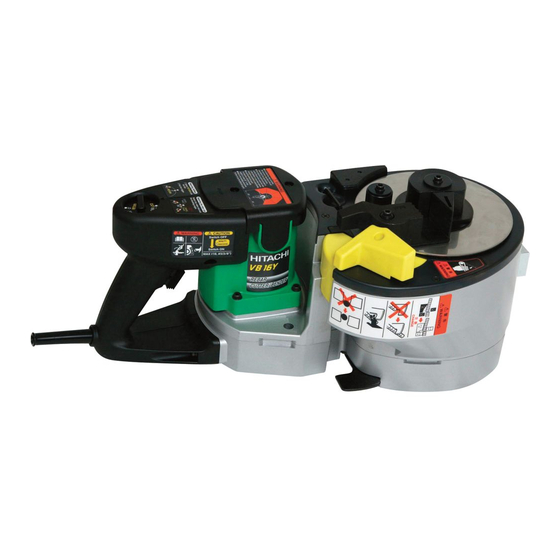
1. PRODUCT NAME Hitachi Portable Rebar Cutter/Bender, Model VB 16Y 2. MARKETING OBJECTIVE A compact and lightweight power tool that reduces worker fatigue and enhances work efficiency. 3. APPLICATIONS Cutting and bending of rebars (concrete reinforcing rod) during construction of foundations and external structures. -
Page 5: Selling Point Descriptions
The Model VB 16Y is equipped with a slip clutch to protect the mechanism. The slip clutch functions if a rebar beyond the capacity of the Model VB 16Y is attempted to be bent or cut. When the slip clutch works, a big slip noise occurs but it is not a malfunction. -
Page 6: Specifications
6. SPECIFICATIONS VB 16Y Model (1) Material; Rebar: Yield strength 460N/mm (47 kgf/mm ) max. Capacities GRADE 460 (Great Britain) BST 500 (Germany) B 500 (Spain) or equivalent grades (2) Max. rebar diameter: 16 mm (5/8") Number of pieces that can be... -
Page 7: Comparisons With Similar Products
(26.5 Ibs.) (37.5 Ibs.) (35.5 Ibs.) 7-1. Working Efficiency Comparison Maker HITACHI HITACHI Model name VB 16Y VB 13Y Capacity Rebar Dia. 16 (5/8") 13 (1/2") 16 (5/8") 62 mm dia. (2-29/64") 36 mm dia. (1-27/64") 38 mm dia. (1-1/2") Center roller diameter 38 mm dia. -
Page 8: How To Use This Unit
10. PRECAUTIONS IN SALES PROMOTION In the interest of promoting the safest and most efficient use of the Model VB 16Y Portable Rebar Cutter/Bender by all of our customers, it is very important that at the time of sale the salesperson carefully ensures that the buyer seriously recognizes the importance of the contents of the Handling Instructions, and fully understands the meaning of the precautions listed on the Caution Plate attached to each tool. -
Page 9: Safety Instructions
PC steel will not only damage the cutter but also there will be a fear of the broken rebar fragments flying around. A slip clutch is built in the Model VB 16Y to protect the mechanism. -
Page 10: Pictograph Illustration And Explanation
11-1. Pictograph Illustration and Explanation If the switch is turned off and then immediately turned on again, the motor Do not use this electric may not start. Wait for at least one full Read handling power tools in wet second before attempting to turn the motor instructions before use. -
Page 11: Precautions In Disassembly And Reassembly
12. PRECAUTIONS IN DISASSEMBLY AND REASSEMBLY The [Bold] numbers in the descriptions below correspond to the item numbers in the Parts List and exploded assembly diagram. 12-1. Disassembly (1) Disassembly of the handle (Fig. 9) (a) Remove the two Tapping Screws (W/Flange) D4 x 20 (Black) [42] and the Tail Cover [101]. (b) Remove the two Tapping Screws (W/Flange) D5 x 20 (Black) [111], four Tapping Screws (W/Flange) D4 x 20 (Black) [42] and two Machine Screws (W/Washers) M5 x 20 (Black) [122] to remove the Handle (A).(B) Set [113]. - Page 12 (3) Disassembly of the bending unit (Fig. 10) (a) Remove the Nylock Bolt (W/Flange) M5 x 16 [6], Washer (A) [34] and Center Roller (D62) Set [35]. Remove the O-ring [9] from the Cam Shaft [12] then remove the Needle Bearing (D22) [36]. (b) Remove the Nylock Bolt (W/Flange) M5 x 25 [37], Sleeve (G) [39], Spring (G) [40] and Guide (D62) [41].
- Page 13 (4) Disassembly of the gear cover (Fig. 11) (a) Remove the two Hex. Socket Hd. Bolts (W/Flange) M4 x 10 [55] from the bottom of the Gear Cover Ass'y [21] and remove the Sensor Cover [30] and the O-Ring [29]. (b) Mark the engagement point between the Sensor Gear [26] and the Sensor Gear [25] with a magic marker.
- Page 14 (5) Disassembly of the gear unit (Figs. 12, 13 and 14) (a) Disassembly of the First Pinion Set [67] (Fig. 12) Press Sleeve (F) [70] press-fitted in the First Pinion Set [67] with a hand press to remove it. Then remove Clutch Spring (F) [69] from the First Gear [68] applying a twist to Clutch Spring (F) [69].
- Page 15 (d) Removal of the Final Gear [17] (Fig. 15) The Final Gear [17] is press-fitted in the Cam Shaft [12]. Remove the Final Gear [17] from the Cam Shaft [12] with the J-321 final gear puller by pressing the end surface of the cam shaft with a hand press as shown in Fig.
- Page 16 (7) Removal of bracket (A) and (B) unit (Fig. 17) (a) Bracket (A) and (B) unit is secured to the Inner Cover Ass'y [13] with two Hex. Socket Hd. Bolts (W/Flange) M8 x 25 [16]. Remove the two Hex. Socket Hd. Bolts (W/Flange) M8 x 25 [16]. Put a core metal whose diameter is the same as the shaft diameter (40 mm) of Bracket (B) [91] on the end surface of Bracket (B) [91] and tap it with a hammer.
-
Page 17: Reassembly
12-2. Reassembly Reassembly can generally be carried out as the reverse of the disassembly procedure, with some items to be noted as follows. (1) Reassembly of the power supply unit (Figs. 19 and 20) Be sure to perform wiring connections as indicated in the wiring diagrams. (a) Be sure to put the connectors in the specified position when connecting the connector of the Cord [125] to the connector of the Controller Circuit [119] (Fig. - Page 18 (2) Reassembly of the cam shaft unit (Fig. 21) [45] [32] Perform reassembly so that the chamfered portion of the Cam Shaft [12] is aligned with the pin of the [10] Cam [10] in the same direction. * Otherwise, the Sensor Gear [26] cannot be [12] mounted in the proper position and there will be a Same...
- Page 19 (6) Installation of bracket (A) and (B) unit to the inner cover (Figs. 24 and 25) Mount the Cover [82] and Spring (F) [83] to the Inner Cover Ass'y [13] first before mounting bracket (A) and (B) unit. Securely fit one end of Spring (F) [83] to the Cover [82] then the other end into the mounting hole of the Inner Cover Ass'y [13].
- Page 20 (9) Installation of Final Gear [17] (Fig. 28) Mount the two Feather Keys 7 x 7 x 25 [46] to the Cam Shaft [12] and gradually press-fit the Cam Shaft [12] into the Final Gear [17] supporting the end surface of the Cam Shaft [12]. After press-fitting, be sure to secure the Final Gear [17] with the Retaining Ring for D28 Shaft [18].
-
Page 21: Confirmation After Reassembly
12-4. Confirmation after Reassembly 12-4-1. Adjustment of turning angle of Roller (B) [8] After reassembly, adjust the turning angle of Roller (B) [8] with the J-322 angle gauge so that rebars can be accurately bent according to the setting of the set dial. (1) Adhering the angle gauge (Fig. - Page 22 (3) If the line "A" on the cam cover is out of the range of the angle gauge mark, finely adjust the bending accuracy as follows (Fig. 31). (a) Unplug the power cord from the receptacle. (b) Remove the tail cover. (c) Take out the printed circuit board for adjustment and slightly turn the fine adjustment volume clockwise if the bending angle is narrow and counterclockwise if the bending angle is wide.
-
Page 23: Tightening Torque
12-5. Tightening Torque Tighten the screws and the bolts according to the following tightening torque. Size and length Tightening torque Tapping Screw (W/Flange) D4 x 20 (Black) [42] 0.5 N m (20 5 kgf • • Tapping Screw (W/Flange) D5 x 20 (Black) [111] 0.5 N m (30 5 kgf... -
Page 24: Standard Repair Time (Unit) Schedules
13. STANDARD REPAIR TIME (UNIT) SCHEDULES Variable 70 min. MODEL Fixed Work Flow VB 16Y Tail Cover Handle (A).(B) Housing Ass'y Bearing Controller Bushing (B) Circuit Ball Bearing O-Ring (608VV) x 2 Volume Holder Stator Ass'y Switch Rubber Fan Guide... - Page 25 LIST NO. 0790 ELECTRIC TOOL PARTS LIST PORTABLE REBAR CUTTER/BENDER 2001 • • Model VB 16Y (E1) 45 46 47...
- Page 26 VB 16Y PARTS ITEM CODE NO. DESCRIPTION REMARKS USED 319-692 CENTER PLATE 319-691 TURN TABLE 320-264 NYLOCK FLAT HD. SCREW M4X12 319-690 CAM COVER 320-427 PLATE (A) 313-082 NYLOCK BOLT (W/FLANGE) M5X16 319-696 WASHER 319-695 ROLLER (B) 944-486 O-RING (1AP-20)
- Page 27 PARTS VB 16Y ITEM CODE NO. DESCRIPTION REMARKS USED 319-683 THIRD GEAR 930-076 METAL (B) 319-661 GUIDE (B) 316-228 HEX. SOCKET HD. BOLT (W/FLANGE) M4X10 880-474 NYLOCK BOLT (W/FLANGE) M6X16 954-789 METAL (B) 320-263 SECOND PINION SET INCLUD.59-64 FEATHER KEY 4X4X10...
-
Page 28: Optional Accessories
VB 16Y PARTS ITEM CODE NO. DESCRIPTION REMARKS USED 318-362 BALL BEARING (A) HITACHI LABEL (B) 310-146 HOUSING ASS’Y INCLUD.93,96 930-703 BRUSH TERMINAL 990-861 INTERNAL WIRE 953-121 HEX. HD. TAPPING SCREW D5X50 360-552E ARMATURE 230V 931-701 BEARING LOCK 302-089 TAPPING SCREW (W/FLANGE) D5X20 (BLACK)