Kenwood TK-980 Service Manual
800mhz/900mhz fm transceiver
Hide thumbs
Also See for TK-980:
- Service manual (33 pages) ,
- Specifications (2 pages) ,
- Instruction manual (49 pages)
Table of Contents
Advertisement
800MHz/900MHz FM TRANSCEIVER
TK-980/981
SERVICE MANUAL
SUPPLEMENT
This service manual applied to products with 30600001 or subsequent serial numbers.
In terms of the products with the serial numbers earlier than 30600001, refer to the TK-980/981 service manual as per
part No. B51-8478-10.
GENERAL ................................................................. 2
OPERATING FEATURES ......................................... 3
REALIGNMENT ...................................................... 13
INSTALLATION ...................................................... 16
CIRCUIT DESCRIPTION ......................................... 25
SEMICONDUCTOR DATA ..................................... 29
DESCRIPTION OF COMPONENTS ....................... 30
PARTS LIST ............................................................ 32
EXPLODED VIEW .................................................. 41
PACKING ................................................................ 42
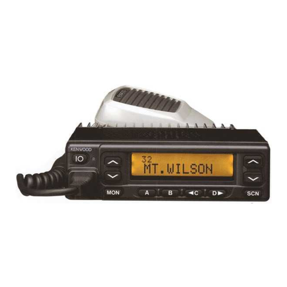
Microphone
(T91-0621-05)
Cabinet (Upper)
(A01-2165-23)
Key top
(K29-5284-02)
CONTENTS
ADJUSTMENT ....................................................... 43
PLL/VCO (X58-4530-XX) .................................. 50
TX-RX UNIT (X57-6520-XX) (A/2) ................... 51
TX-RX UNIT (X57-6520-XX) (B/2) .................... 57
SCHEMATIC DIAGRAM ........................................ 61
BLOCK DIAGRAM.................................................. 69
LEVEL DIAGRAM................................................... 72
TERMINAL FUNCTION ......................................... 74
SPECIFICATIONS................................................... 75
© 2001-9 PRINTED IN JAPAN
B51-8588-00 ( N ) 1016
Panel assy
(A62-0991-03)
Advertisement
Table of Contents

Related Manuals for Kenwood TK-980


Summary of Contents for Kenwood TK-980
-
Page 1: Table Of Contents
B51-8588-00 ( N ) 1016 This service manual applied to products with 30600001 or subsequent serial numbers. In terms of the products with the serial numbers earlier than 30600001, refer to the TK-980/981 service manual as per part No. B51-8478-10. -
Page 2: General
TK-980/981 GENERAL 3-2. Testing INTRODUCTION The radio should be tested complete with all cabling and SCOPE OF THIS MANUAL accessories as they will be connected in the final installa- This manual is intended for use by experienced techni- tion. Transmitter frequency, deviation, and power output... - Page 3 5. INSTALLATION PLANNING – CONTROL STATIONS 1. Operation Features 5-1. Antenna system The TK-980/981 is an 800MHz/900MHz band EFJ LTR™ - Control station. The antenna system selection depends compatible trunked radio designed to operate in both on many factors and is beyond the scope of this manual.
-
Page 4: Operating Features
TK-980/981 OPERATING FEATURES • AUX-A • Horn Alert If this key is pressed, “AUX” icon lights on the LCD and If you are called from the base station using DTMF while AUX port which is inside of the transceiver turns to the high you are away from your transceiver, you will be alerted by level. - Page 5 TK-980/981 OPERATING FEATURES • Scan Temporary Delete P (Priority) indicator This key is temporarily deleted a system being scanned. The P indicator ( ) appears when a selected group is pro- If you press this key when scan is stopped (when a call is grammed as priority, in conventional operation.
- Page 6 TK-980/981 OPERATING FEATURES Dwell Time 3. Scan Operating The dwell time is the time after transmission ends until System Scan the scan resumes in scan mode. It can be set 0 to 300 sec- System scan can be selected with the “Scan” key by pro- onds by programming.
- Page 7 TK-980/981 OPERATING FEATURES In Conventional System Off Hook Decode If QT or DQT is set for the group, the groups, including If the Off hook decode function has been enabled, re- signalling, are scanned. moving and replacing the microphone on the hook has no In case of the priority group is set in conventional system, effect for decoding QT/DQT and option signalling.
- Page 8 TK-980/981 OPERATING FEATURES Continuous Free System Ringback Horn alert can be reset by setting an expiration time from This feature is available only when a telephone intercon- the FPU, pressing the any key, or setting off hook. nected ID code is selected. If a busy tone sounds when the PTT button is pressed, the transceiver enters this mode au- tomatically.
-
Page 9: Option Signalling
T h e A l p h a n u m e r i c T w o - w a y P a g i n g F u n c t i o n If the selective call alert LED is set up, the orange LED (FleetSync™) is a Kenwood proprietary protocol. It enables will flash. - Page 10 TK-980/981 OPERATING FEATURES Selective Call (SELCALL) • Automatic Status Response This is a voice call to a particular individual or group of If you pre-select a status number and leave the radio in stations. the Status Mode, it can automatically respond with the se- lected status number upon request from the base station.
- Page 11 • Call Alert (Continuous) 2) MAP HEADER KW1 ($PKLDS) The radio can provide the alert tone repeatedly until next This is a Kenwood original sentence which consists of operation. “$GPGLL + Fleet + ID + Status”. This item should be set according to your PC application.
-
Page 12: Audible User Feedback Tones
TK-980/981 OPERATING FEATURES • ACK Delay Time Group Call Tone ACK Delay Time is the amount of time from the end of Sounds when a group call with the correct DTMF option receiving a data to the beginning of sending an signalling is received, repeats 7 times. -
Page 13: Realignment
TK-980/981 OPERATING FEATURES / REALIGNMENT Proceed Tone REALIGNMENT This tone is output when the PTT button is pressed, transmission starts, and the repeater is connected to indi- 1. Modes cate that the user can talk if the clear to talk function has been set. - Page 14 TK-980/981 REALIGNMENT 5-5. Programming With IBM PC 5. PC Mode If data is transferred to the transceiver from an IBM PC 5-1. Preface with the KPG-49D, the destination data (basic radio informa- The transceiver is programmed by using a personal com- tion) for each set can be modified.
-
Page 15: Clone Mode
TK-980/981 REALIGNMENT 6-4. Function 6. Press the [SCN] key on the master while the master dis- plays “CLONE MODE”. The data of the master is sent to 1. If you press the [MON] switch while “PROG 57600” is the slave. While the slave is receiving the data, “PRO- displayed, the checksum is displayed. -
Page 16: Installation
TK-980/981 INSTALLATION 1-2. Accessory Port Function 1. Accessory Connection Cable No. (A) No. (B,C,D,E) Name Function Note (KCT-19 : Option) External hook input The KCT-19 is an accessory connection cable for con- BUSY System busy output necting external equipment. The connector has 15 pins and the necessary signal lines are selected for use. - Page 17 TK-980/981 INSTALLATION 1-3. Data Equipment Connection The jumpers must be set to either one for each function. Otherwise, the radio will not work properly. AHK/BUSY R64 (0Ω) R18 (0Ω) Function BUSY System busy output indicates if no TX-RX unit (A/2)
- Page 18 TK-980/981 INSTALLATION 3. Optional Board Terminal Connector Pin Function name Terminal is for mounting the option board are provided at the TX-RX unit (A/2) and TX-RX unit (B/2). The table below O Squelch signal output. Signal logic shows the correspondence between the board and termi- type can select “Carrier operate...
- Page 19 TK-980/981 INSTALLATION RSSI TX-RX unit (A/2) Foil side view KCT-19 Contact KCT-18 Fig. 3 4-2. Modifying the Transceiver Modify the transceiver as follows to turn the power or TX-RX unit (A/2) the Horn Alert or Manual Relay function on and off with the Component side view ignition key.
- Page 20 6. Interface Cable (KCT-31 : Option) The KCT-29 connection cable kit is used to connect the The KCT-31 is a RS-232C interface cable for LMR mobile TK-980/981 transceiver to the KPG-1A Modem GPS Re- radios, TK-980/981. ceiver or the KPG-1B Modem GPS Controller.
- Page 21 When the COM1 is used. When the COM2 is used. Fig. 9 Note : · The modification must be applied to the TK-980/981 · Enable the serial port function on the terminal. transceivers with a serial number of 30600000 or smaller ·...
- Page 22 TK-980/981 INSTALLATION 7. PA/HA Unit (KAP-1 : Option) Output form 7-1. Installing the KAP-1 in the Transceiver HR1 (Default) The Horn Alert (max. 2A drive) and Public Address func- tions are enabled by inserting the KAP-1 W1 (3P; white/ black/red) into CN3 on the TX-RX unit (A/2), inserting W2 (3P;...
- Page 23 8. Fitting the Control Panel Upside Down 2. Fold the flat cable ( ) in the opposite direction ( The TK-980/981 control panel can be fitted upside down, 3. Rotate the control section ( ) 180 degrees ( so the transceiver can be mounted with its internal speaker 4.
-
Page 24: External Speaker
TK-980/981 INSTALLATION 9-2. KES-4 : Option 6. Rotate the control panel 180 degrees and mount it on the transceiver. Refit the two halves of the case to complete The KES-4 is an external speaker used with the acces- installation. (Fig. 16) sory connection cable. -
Page 25: Circuit Description
TK-980/981 CIRCUIT DESCRIPTION AF Signal System Frequency Configuration The detection signal (DEO) from the TX-RX unit (A/2) The TX-RX unit (A/2) incorporates a VCO, based on a frac- goes to the audio processor (IC504) of the TX-RX unit (B/2). tional N type PLL synthesizer system, that allows a channel The signal passes through a filter in the audio processor to step of 12.5kHz to be selected. - Page 26 The APC circuit controls voltage in the younger final stage (Q204). PLL lock : LD “H” VCO/PLL Circuit The TK-980/981 has a common VCO for the transmitter IC508 IC300 IC511 SHIFT and the receiver in a sub-unit (A1). It is housed in a solid REG.
- Page 27 Key Matrix Circuit modulation and transmission power. The TK-980/981 front panel has ten keys. Each of them is connected to a cross point of a matrix of the KEY1 to KEY7 ports of the microprocessor. The KEY5 to KEY7 ports are LCD ASSY always high, while the KEY1 to KEY4 ports are always low.
- Page 28 TK-980/981 CIRCUIT DESCRIPTION Decode PA Switch The signal (DEO) detected by the TX-RX unit (A/2) passes If the optional KAP-1 is used, the PA (Public Address) through two low-pass filters of IC501, goes to LSDI of the function becomes available. In this case, the signal flow CPU (IC511) to decode QT, DQT, and LTR.
-
Page 29: Semiconductor Data
TK-980/981 SEMICONDUCTOR DATA Microprocessor : 30622M8A-4F9GP (TX-RX Unit (B/2) IC511) Terminal function Pin No. Name Function Pin No. Name Function LSDOUT Low speed data output. RFCLK Common clock output. (TX-RX unit A/2) HSDOUT High speed data output. – Not used. -
Page 30: Description Of Components
Port Name Function DESCRIPTION OF COMPONENTS Strobe Data TX-RX Unit (X57-6520-XX) (A/2) Clock -10 : TK-980 -11 : TK-981 Audio mute 1. H : Mute, L : Unmute Ref. No. Use / Function Operation / Condition Link complete. IC1~3 Amplifier... - Page 31 Excessive input protection DC switch D208~210 RF switch TX/RX DC switch HOR CONT. TX-RX Unit (X57-6520-XX) (B/2) Buffer amplifier -10 : TK-980 -11 : TK-981 Q8,9 AF mute switch Q10,11 DC switch Ref. No. Use / Function Operation / Condition Q12,13...
-
Page 32: Parts List
TK-980/981 PARTS LIST CAPACITORS CC 45 TH 1H 220 J • Capacitor value Color* CC45 010 = 1pF 0 = 22pF 100 = 10pF 1 = Type … ceramic, electrolytic, etc. 4 = Voltage rating Multiplier 101 = 100pF 2 = Shape … round, square, ect. - Page 33 CHIP C 1000PF C92-0719-05 ELECTRO 47UF 25WV C92-0044-05 CHIP-ELE 47UF 10WV CK73GB1H102K CHIP C 1000PF TX-RX UNIT (X57-6520-XX) -10 : TK-980 -11 : TK-981 C92-0719-05 ELECTRO 47UF 25WV D511 B30-2151-05 LED (RED/GRE) CK73GB1E103K CHIP C 0.010UF D512-517 B30-2171-05 LED (D)
- Page 34 TK-980/981 PARTS LIST TX-RX UNIT (X57-6520-XX) Desti- Desti- Ref. No. Address Parts No. Description Ref. No. Address Parts No. Description parts nation parts nation CK73GB1H102K CHIP C 1000PF C173 CK73GB1E103K CHIP C 0.010UF CC73GCH1H101J CHIP C 100PF C174 C92-0585-05 CHIP-TAN 4.7UF...
- Page 35 TK-980/981 PARTS LIST TX-RX UNIT (X57-6520-XX) Desti- Desti- Ref. No. Address Parts No. Description Ref. No. Address Parts No. Description parts nation parts nation C271 C93-0550-05 CHIP C 1.0PF C531 CK73GB1H562K CHIP C 5600PF C272 CC73GCH1H010C CHIP C 1.0PF C533...
- Page 36 TK-980/981 PARTS LIST TX-RX UNIT (X57-6520-XX) Desti- Desti- Ref. No. Address Parts No. Description Ref. No. Address Parts No. Description parts nation parts nation C614 CK73GB1H102K CHIP C 1000PF L224 L34-1306-15 AIR-CORE COIL C616 CK73GB1H102K CHIP C 1000PF L225 L92-0179-05...
- Page 37 TK-980/981 PARTS LIST TX-RX UNIT (X57-6520-XX) Desti- Desti- Ref. No. Address Parts No. Description Ref. No. Address Parts No. Description parts nation parts nation RK73GB1J104J CHIP R 100K 1/16W R134 RK73GB1J473J CHIP R 1/16W RK73GB1J103J CHIP R 1/16W R135 R92-1261-05...
- Page 38 TK-980/981 PARTS LIST TX-RX UNIT (X57-6520-XX) Desti- Desti- Ref. No. Address Parts No. Description Ref. No. Address Parts No. Description parts nation parts nation R307 R92-1252-05 CHIP R 0 OHM J 1/16W R551 RK73GB1J223J CHIP R 1/16W R308 RK73GB1J101J CHIP R...
- Page 39 IC400 M67760HC HYBRID IC TK-981 157-104-55001 THERMISTOR IC400 M67760LC HYBRID IC TK-980 IC501 TA75W558FU MOS IC PLL/VCO (X58-4530-XX) -10 : TK-980 -11 : TK-981 IC502 TC75W51FU MOS IC IC503 TA75W558FU MOS IC C100 CK73GB1H471K CHIP C 470PF IC504 TC35453F MOS IC...
- Page 40 TK-980/981 PARTS LIST PLL/VCO (X58-4530-XX) Desti- Desti- Ref. No. Address Parts No. Description Ref. No. Address Parts No. Description parts nation parts nation C111 CC73GCH1H470J CHIP C 47PF C112 CK73GB1H471K CHIP C 470PF C113 CC73GCH1H040B CHIP C 4.0PF TK-980 C113...
-
Page 41: Exploded View
TK-980/981 EXPLODED VIEW Parts with the exploded numbers larger than 700 are not supplied. -
Page 42: Packing
29 Polystyrene foamed fixture (H10-6619-12) 31 Protection bag 705 Warranty card (H25-0720-04) 7 Instruction manual (B62-1549-00) 28 Polystyrene foamed fixture 32 Item carton case (H10-6618-12) (H52-1431-02) : TK-980 (H52-1432-02) : TK-981 Parts with the exploded numbers larger than 700 are not supplied. -
Page 43: Adjustment
TK-980/981 ADJUSTMENT • Frequency (MHz) Test Mode Channel TK-980 TK-981 Test Mode Operating Features RX (TX : TA) RX (TX : TA) This transceiver has a test mode. To enter test mode, 851.05000 806.05000 935.0250 896.0250 press [A] key and turn power on. Hold [A] key until test channel No. - Page 44 Max deviation (C) Max deviation (H) NMAX 256 L NMAX 256 C NMAX 256 H NMAX 256 Max deviation (NPSPAC TK-980) Max deviation (NPSPAC) (L) Max deviation (NPSPAC) (C) [C] Max deviation (NPSPAC) (H) BAL 256 L BAL 256 C BAL 256...
- Page 45 –127dBm/0.1µV to greater than –7dBm/100mV 2. Power Meter Input Impedance 50Ω Operation Frequency 806 to 870MHz or more (TK-980), 896 to 941MHz (TK-981) Measurement Capability Vicinity of 30W 3. Deviation Meter Frequency Range 806 to 870MHz (TK-980), 896 to 941MHz (TK-981) 4.
- Page 46 Repair Jig (Chassis) Use jig (Part No. : A10-4010-02) for repairing the • EEPROM TK-980/981. The jig facilitates the voltage check The tuning data (Deviation, Squelch, etc.) for the when the voltage on the component side TX-RX unit EEPROM, is stored in memory. When parts are changed, (A/2) is checked during repairs.
- Page 47 : 860.5MHz (TK-980) : 938.025MHz (TK-981) SSG output : Value when 2dB is subtracted from the sensitivity value of 12dB SINAD. SSG MOD : 3kHz (TK-980) 1.5kHz (TK-981) 4. Squelch 1) Set test mode Check Squelch must be opened. check...
- Page 48 2) “C BAL” PTT : ON 3) “H BAL” PTT : ON ± 50Hz 7. Maximum 1) Set test mode 3.8kHz (TK-980) deviation Connect AG to the MIC terminal. 1.75kHz (TK-981) Select “MAX” in tuning mode. (According to the “L MAX”...
- Page 49 Test- Unit Terminal Unit Parts Method equipment 9. MIC 1) Set test mode Power meter Rear Check 2.2~3.8kHz (TK-980) sensitivity CH : CH4 - Sig1 Deviation panel 1.1~1.9kHz (TK-981) check AG : 1kHz/5mV meter PTT : ON Oscilloscope ± 50Hz 10.
-
Page 50: Pc Board Views
TK-980/981 PC BOARD VIEWS PLL/VCO (X58-4530-XX) -10 : TK-980 -11 : TK-981 Component side view J72-0608-02 R108 Q100 CN100 Q102 C117 C104 R114 C115 C109 R112 R111 R109 R107 R102 R101 C103 C113 L103 C101 L101 PLL/VCO (X58-4530-XX) -10 : TK-980 -11 : TK-981... -
Page 51: Tx-Rx Unit (X57-6520-Xx) (A/2)
TK-980/981 PC BOARD VIEW TX-RX UNIT (X57-6520-XX) (A/2) -10 : TK-980 -11 : TK-981 Component side view Ref No. Address Ref No. Address Ref No. Address Ref No. Address Component side IC10 Q205 Pattern 1 IC400 IC11 Q300 Pattern 2... - Page 52 TK-980/981 PC BOARD VIEW TX-RX UNIT (X57-6520-XX) (A/2) -10 : TK-980 -11 : TK-981 Ref. No. Address Ref. No. Address Ref. No. Address Ref. No. Address Ref. No. Address Ref. No. Address Foil side view IC400 Q203 D209 Q204 D210...
- Page 53 TK-980/981 PC BOARD VIEW TX-RX UNIT (X57-6520-XX) (A/2) -10 : TK-980 -11 : TK-981 Ref. No. Address Ref. No. Address Ref. No. Address Ref. No. Address Ref. No. Address Ref. No. Address Ref. No. Address Component side view + Foil side...
-
Page 54: Tx-Rx Unit (X57-6520-Xx) (B/2)
TK-980/981 PC BOARD VIEWS TX-RX UNIT (X57-6520-XX) (B/2) -10 : TK-980 -11 : TK-981 Component side view D512 D517 C527 C518 C583 R526 L507 R525 R682 IC502 C524 R572 D511 IC501 C592 IC508 R531 R502 R507 C513 C506 C510 +... - Page 55 TK-980/981 PC BOARD VIEW TX-RX UNIT (X57-6520-XX) (B/2) -10 : TK-980 -11 : TK-981 Component side view + Foil side D517 D512 R520 C607 MPTT C516 R518 C515 CN501 C527 C518 RXAO C583 R680 R521 R526 L507 R525 C524 R673...
-
Page 56: Schematic Diagram
TK-980/981 Note : Components marked with a dot (·) are parts of pattern 1. SCHEMATIC DIAGRAM... - Page 57 TK-980/981 SCHEMATIC DIAGRAM Note : Components marked with a dot (·) are parts of pattern 1.
-
Page 58: Block Diagram
TK-980/981 TK-980/981 TK-980/981 BLOCK DIAGRAM... -
Page 59: Level Diagram
TK-980/981 TK-980/981 LEVEL DIAGRAM Receiver Section Transmitter Section... -
Page 60: Terminal Function
TK-980/981 TERMINAL FUNCTION CN7 (TX-RX Unit A/2) ← → CN502 (TX-RX Unit B/2) CN101 (VCO) ← → TX-RX Unit (A/2) Pin No. Name Function Pin No. Name Function Wide/Narrow switch input. H : Wide Ground. TX/RX switch input. H : Receive Signal output. -
Page 61: Specifications
FM Noise ..........TK-980 : –45dB TK-981 : –40dB Microphone Impedance ...... Low impedance Audio Distortion ........TK-980 : 3% or less at 1kHz TK-981 : 5% or less at 1kHz Frequency Stability ......± 1.5ppm from –30°C to +60°C Channel Frequency Spread .... - Page 62 Mechelsesteenweg 418 B-1930 Zaventem, Belgium KENWOOD ELECTRONICS FRANCE S.A. 13, Boulevard Ney, 75018 Paris, France KENWOOD ELECTRONICS U.K. LIMITED KENWOOD House, Dwight Road, Watford, Herts., WD1 8EB United Kingdom KENWOOD ELECTRONICS EUROPE B.V. Amsterdamseweg 37, 1422 AC Uithoorn, The Netherlands KENWOOD ELECTRONICS ITALIA S.p.A.