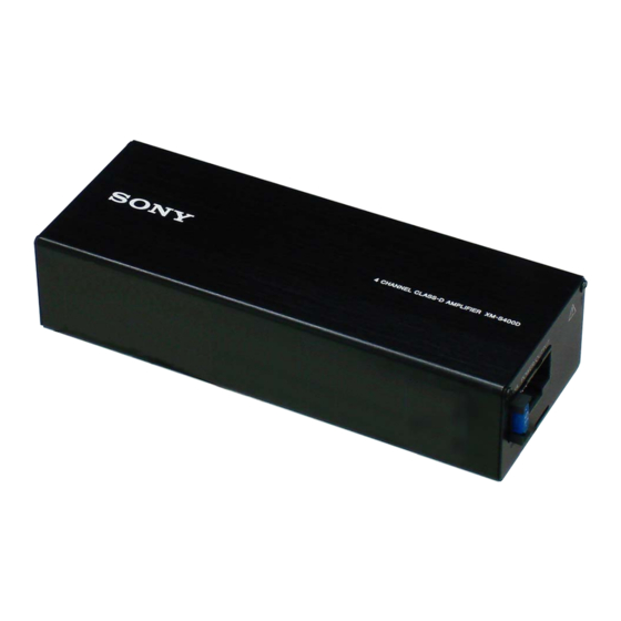
Sony XM-S400D Operating Instructions Manual
4 channel class-d
amplifier
Hide thumbs
Also See for XM-S400D:
- Operating instructions manual (160 pages) ,
- Operating instructions manual (15 pages) ,
- Service manual (17 pages)
Table of Contents
Advertisement
Quick Links
Advertisement
Table of Contents

Summary of Contents for Sony XM-S400D
- Page 1 4-581-373-21(2) 4 Channel Class-D Operating Instructions Amplifier XM-S400D...
- Page 2 This symbol is intended to alert the user to the presence of a hot surface. The symbol applies to Europe models only. If you have any questions or problems concerning your unit that are not covered in this manual, please consult your nearest Sony dealer.
-
Page 3: Table Of Contents
Features Table of Contents Maximum power output of 100 W per channel (at Features ........3 4 Ω). -
Page 4: Operation
Operation Location and Function of Controls POWER/PROTECT indicator FRONT HPF (high-pass filter) switch Lights up in green during operation. Sets the high-pass filter (HPF) to “ON” or “OFF.” If the protection circuit activates, the POWER/ Slit for the supplied bracket PROTECT indicator flashes. -
Page 5: Installation And Connections
The unit will not come into contact with a driver/passengers or materials in your car since the unit becomes hot during use. Installation and Connections Do not install the unit under the floor carpet, where the heat dissipation from the unit will be Parts for Installation and considerably impaired. -
Page 6: Connections
Place the unit on the mounting board Power Connections and secure it with the supplied mounting screws . Connect the +12 V power supply wire only after all the other wires have been connected and the settings on this unit have been made. ... -
Page 7: Input Connections
Making power connections Input Connections Connect the supplied power connection cable to the POWER/OUTPUT connector on the unit. Set the INPUT SELECT switch to “2CH” or “4CH” according to the input connection. Also, refer to the manual supplied with your car audio unit for further details. - Page 8 High level input connection High level input connection Set the INPUT SELECT switch to “4CH” with the Set the INPUT SELECT switch to “2CH” with the speaker connection (page 9). speaker connection (page 9). Gray Gray Front right speaker output Front right speaker output Gray/Striped...
-
Page 9: Speaker Connections
2-way system Speaker Connections Set with the input connection (page 7) or Set the REAR LPF switch and FRONT HPF switch to (page 8). “ON” or “OFF” according to the speaker system. Also, refer to the manual supplied with your speakers for further details. -
Page 10: Additional Information
If you have any questions or problems concerning your unit that are not covered in this manual, please consult your nearest Sony dealer. Additional Information Precautions Maintenance This unit is designed for negative ground (earth) 12 V DC operation only. -
Page 11: Specifications
Dimensions Specifications Approx. 162.8 mm × 37.3 mm × 62.6 mm (w/h/d) not incl. projecting parts and controls AUDIO POWER SPECIFICATIONS CEA2006 Standard Power Output: 45 Watts RMS × 4 at 4 Ohms < 1% THD+N SN Ratio: 83 dBA (reference: 1 Watt into 4 Ohms) Circuit system ... -
Page 12: Troubleshooting
If these solutions do not help improve the situation, determine the cause of the short circuits. consult your nearest Sony dealer. The speaker cord and ground (earth) wire are not securely connected. Take out any media from the car audio unit and... - Page 16 ©2015 Sony Corporation Printed in Thailand...


