Table of Contents
Advertisement
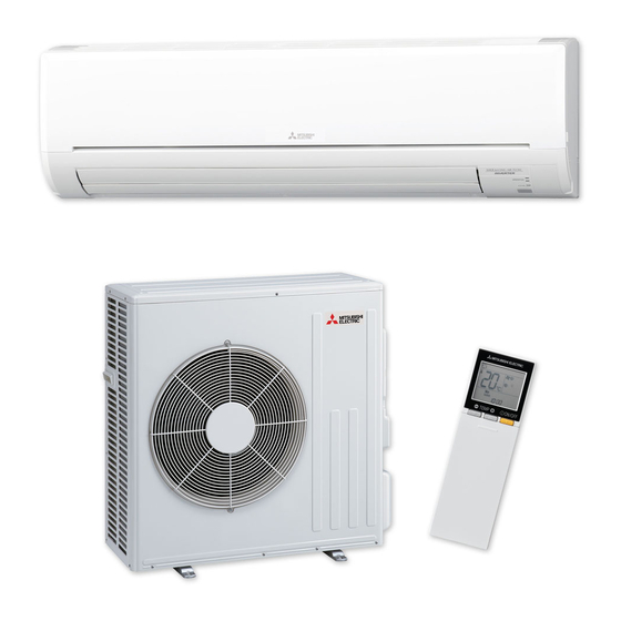
SPLIT-TYPE AIR CONDITIONERS
INSTALLATION MANUAL
1. BEFORE INSTALLATION
MEANINGS OF SYMBOLS DISPLAYED ON INDOOR UNIT AND/OR OUTDOOR UNIT
WARNING
Read the OPERATING INSTRUCTIONS carefully before operation.
Service personnel are required to carefully read the OPERATING INSTRUCTIONS and INSTALLATION MANUAL before operation.
Further information is available in the OPERATING INSTRUCTIONS, INSTALLATION MANUAL, and the like.
1-1. THE FOLLOWING SHOULD ALWAYS BE OBSERVED FOR SAFETY
■ Do not install the unit by yourself (user).
injury due to the unit falling, or leakage of water. Consult
installer.
■ Perform the installation securely referring to the
installation manual.
injury due to the unit falling, or leakage of water.
■ When installing the unit, use appropriate protective
equipment and tools for safety.
Failure to do so could cause injury.
■ Install the unit securely in a place which can bear the
weight of the unit.
If the installation location cannot bear the weight of the
unit, the unit could fall causing injury.
■
experienced electrician, according to the installation
manual. Be sure to use an exclusive circuit. Do not
connect other electrical appliances to the circuit.
electric shock.
■ Earth the unit correctly.
Do not connect the earth to a gas pipe, water pipe, light-
ning rod, or telephone earth. Defective earthing could
cause electric shock.
■ Do not damage the wires by applying excessive pres-
sure with parts or screws.
■ Be sure to cut off the main power in case of setting
up the indoor P.C. board or wiring works.
Failure to do so could cause electric shock.
■
the terminal block connecting sections so the stress
of the wires is not applied to the sections. Do not
extend the wires, or use intermediate connection.
■
gas may leak.
If gas leaks and accumulates in the area around the unit,
it could cause an explosion.
■ Do not use intermediate connection of the power
cord or the extension cord and do not connect many
devices to one AC outlet.
contact, defective insulation, exceeding the permissible
current, etc.
■ Install an earth leakage breaker depending on the
installation place.
If an earth leakage breaker is not installed, it could cause
electric shock.
■ Perform the drainage/piping work securely according
to the installation manual.
If there is defect in the drainage/piping work, water could
drop from the unit, soaking and damaging household goods.
REFRIGERANT
Model names are indicated in 1-3.
■
for the installation work.
The use of defective parts could cause an injury or leakage
etc.
■ When plugging the power supply plug into the outlet,
make sure that there is no dust, clogging, or loose
parts in both the outlet and the plug. Make sure that
the power supply plug is pushed completely into the
outlet.
If there is dust, clogging, or loose parts on the power
supply plug or the outlet, it could cause electric shock or
replace it.
■ Attach the electrical cover to the indoor unit and the
service panel to the outdoor unit securely.
If the electrical cover of the indoor unit and/or the service
panel of the outdoor unit are not attached securely, it could
■ When installing, relocating, or servicing the unit,
refrigerant (R32) enters the refrigerant circuit.
Any presence of foreign substance such as air can cause
abnormal pressure rise and may result in explosion or
injury. The use of any refrigerant other than that speci-
malfunction, or unit breakdown. In the worst case, this
could lead to a serious impediment to securing product
safety.
■ Do not discharge the refrigerant into the atmosphere.
If refrigerant leaks during installation, ventilate the
room. Check that the refrigerant does not leak after
installation has been completed.
ing part of such a fan heater, kerosene heater, or cooking
stove, it will create harmful gas.
■ Use appropriate tools and piping materials for instal-
lation.
The pressure of R32 is 1.6 times more than R22. Not using
appropriate tools or materials and incomplete installation
could cause the pipes to burst or injury.
■ When pumping down the refrigerant, stop the com-
pressor before disconnecting the refrigerant pipes.
If the refrigerant pipes are disconnected while the com-
pressor is running and the stop valve is open, air could be
drawn in and the pressure in the refrigeration cycle could
become abnormally high. This could cause the pipes to
burst or injury.
■
outdoor unit.
This could cause injury.
■ Do not install the outdoor unit where small animals
may live.
If small animals enter and touch the electric parts inside the
Also, advise user to keep the area around the unit clean.
JG79B530H01
Phillips screwdriver
Level
Scale
Utility knife or scissors
75 mm hole saw
Torque wrench
Wrench (or spanner)
Appropriate personal protective equipment
The installer should ensure they check the respective Work Health
and Safety (WHS) Act within their jurisdiction as the requirements
and obligations may differ.
WARNING
(Could lead to death, serious injury, etc.)
-
CAUTION
(Could lead to serious injury in particular environments when operated incorrectly.)
Required Tools for Installation
4 mm hexagonal wrench
Flare tool for R32, R410A
Gauge manifold for R32, R410A
Vacuum pump for R32, R410A
Charge hose for R32, R410A
Pipe cutter with reamer
■ When installing the unit, securely connect the refriger-
ant pipes before starting the compressor.
If the compressor is started before the refrigerant pipes are
connected and when the stop valve is open, air could be
drawn in and the pressure in the refrigeration cycle could
become abnormally high. This could cause the pipes to
burst or injury.
■
in this manual.
period and cause refrigerant leakage.
■ The unit shall be installed in accordance with national
wiring regulations.
■
equipment, completely remove all of the refrigerant
from the air conditioner and ensure that the area is
well-ventilated.
heating part, it will create harmful gas and there is risk of
■ Do not use means to accelerate the defrosting process
or to clean, other than those recommended by the
manufacturer.
■ The appliance shall be stored in a room without
continuously operating ignition sources (for exam-
operating electric heater.
■ Do not pierce or burn.
■ Be aware that refrigerants may not contain an odour.
■ Pipe-work shall be protected from physical damage.
■ The installation of pipe-work shall be kept to a mini-
mum.
■ Compliance with national gas regulations shall be
observed.
■ Keep any required ventilation openings clear of ob-
struction.
■ In Australia, only technicians that possess the appro-
priate license issued by the Australian Refrigeration
Council (ARC) should install this product.
Advertisement
Table of Contents

Related Manuals for Mitsubishi Electric MSZ-GL71VGD


Summary of Contents for Mitsubishi Electric MSZ-GL71VGD
-
Page 1: Installation Manual
Required Tools for Installation JG79B530H01 REFRIGERANT Phillips screwdriver 4 mm hexagonal wrench Level Flare tool for R32, R410A Scale Gauge manifold for R32, R410A Model names are indicated in 1-3. Utility knife or scissors Vacuum pump for R32, R410A 75 mm hole saw Charge hose for R32, R410A SPLIT-TYPE AIR CONDITIONERS Torque wrench... -
Page 2: Selecting The Installation Location
Demand control signal Indoor unit Outdoor unit Rated Voltage Frequency Gas / Liquid capacity supply *2 necting wire *2 transmission cable *3 MSZ-GL71VGD MUZ-GL71VGD 3-core 4-core ø12.7 / 6.35 mm 230 V 50 Hz 20 A 0.5 - 1.5 mm... -
Page 3: Installation Diagram
1-4. INSTALLATION DIAGRAM ACCESSORIES PARTS TO BE PROVIDED AT YOUR SITE Check the following parts before installation. <Indoor unit> Note: (1) Installation plate (A) Indoor/outdoor unit connecting wire*1 *1 Place indoor/outdoor unit connecting wire (A) (B) Extension pipe and power supply cord (K) at least 1 m away 4 ×... -
Page 4: Indoor Unit Installation
2. INDOOR UNIT INSTALLATION 2-1. FIXING OF INSTALLATION PLATE 2-4. PIPE FORMING AND DRAIN PIPING Felt tape (4) Pipe Forming Piping tape (G) Liquid pipe Gas pipe in other holes. Indoor/outdoor unit tion material (obtainable at a store) around it. connecting wire (A) ing the wires. -
Page 5: Insulation/Taping
3. OUTDOOR UNIT INSTALLATION 3-1. CONNECTING WIRES FOR OUTDOOR UNIT A (mm) Tightening torque Pipe diameter 1) Open the service panel. Clutch type Clutch type Wing nut (mm) (mm) tool for tool type tool 2) Loosen terminal screw, and connect indoor/outdoor unit connecting wire (A) from R32,R410A for R22 for R22... -
Page 6: Purging Procedures, Leak Test, And Test Run
4. PURGING PROCEDURES, LEAK TEST, AND TEST RUN 4-1. PURGING PROCEDURES AND LEAK TEST 4-2. TEST RUN 1) Remove service port cap of stop valve on the side of the outdoor unit gas pipe. (The stop 1) Insert power supply plug into the power outlet and/or turn on valves are fully closed and covered in caps in initial state.) the breaker. -
Page 7: Relocation And Maintenance
5. RELOCATION AND MAINTENANCE 5-1. REMOVING AND INSTALLING THE PANEL ASSEMBLY 5-3. PUMPING DOWN When relocating or disposing of the air conditioner, pump down the system following the Removal procedure procedure below so that no refrigerant is released into the atmosphere. 1) Connect the gauge manifold valve to the service port of the stop valve on the gas pipe 2) Remove the panel assembly. - Page 8 HEAD OFFICE: TOKYO BLDG., 2-7-3, MARUNOUCHI, CHIYODA-KU, TOKYO 100-8310, JAPAN...