Table of Contents
Advertisement
Advertisement
Table of Contents

Related Manuals for Panasonic MDF-U7386S


Summary of Contents for Panasonic MDF-U7386S
-
Page 1: Operating Instructions
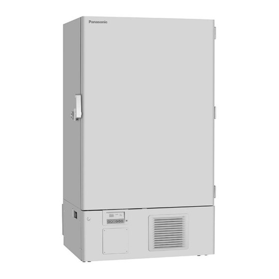
Operating Instructions Ultra-Low Temperature Freezer MDF-U7386S MDF-U7386SC MDF-U5386S MDF-U5386SC MDF-U7386S MDF-U5386S Series MDF-U7386S Please read these instructions carefully before using this product, and save this operating instructions for future use. See page 35 for all Model numbers. -
Page 2: Table Of Contents
CONTENTS INTRODUCTION P. 2 PRECAUTIONS FOR SAFE OPERATION P. 3 ENVIRONMENTAL CONDITIONS P. 7 FREEZER COMPONENTS P. 8 Control panel P.10 INSTALLATION SITE P.11 INSTALLATION P.12 START-UP OF UNIT P.13 CHAMBER TEMERATURE SETTING P.14 KEY LOCK FUNCTION P.14 ALARM TEMPERATURE SETTING P.15 SETTING OF ALARM RESUME TIME P.16... -
Page 3: Introduction
INTRODUCTION Read this operating instructions carefully before using the appliance and follow the instructions for safety operation. Our company never guarantee any safety if the appliance is used for any objects other than intended use or used by any procedures other than those mentioned in this operating instructions. Keep this operating instructions in an adequate place to refer to it as necessary. -
Page 4: Precautions For Safe Operation
PRECAUTIONS FOR SAFE OPERATION It is imperative that the user complies with this operating instructions as it contains important safety advice. Items and procedures are described so that you can use this unit correctly and safely. If the precautions advised are followed, this will prevent possible injury to the user and any other person. - Page 5 PRECAUTIONS FOR SAFE OPERATION WARNING Do not use the unit outdoors. Current leakage or electric shock may result if the unit is exposed to rain water. Only qualified engineers or service personnel should install the unit. The installation by unqualified personnel may cause electric shock or fire. Install the unit on a sturdy floor and take an adequate precaution to prevent the unit from turning over.
- Page 6 PRECAUTIONS FOR SAFE OPERATION WARNING Ensure you do not inhale or consume medication or aerosols from around the unit at the time of maintenance. These may be harmful to your health. Never splash water directly onto the unit as this may cause electric shock or short circuit. Never put containers with liquid on the unit as this may cause electric shock or short circuit when the liquid is spilled.
- Page 7 PRECAUTIONS FOR SAFE OPERATION CAUTION Use a dedicated power source (a dedicated circuit with a breaker) as indicated on the rating label attached to the unit. A branched circuit may cause fire resulting from abnormal heating. Connect the power supply plug to the power source firmly after removing the dust on the plug. A dusty plug or improper insertion may cause a heat or ignition.
-
Page 8: Environmental Conditions
ENVIRONMENTAL CONDITIONS This equipment is designed to be safe at least under the following conditions (based on the IEC 61010-1): Indoor use; Altitude up to 2000 m; Ambient temperature 5 C to 40 Maximum relative humidity 80% for temperature up to 31 C decreasing linearly to 50% relative humidity at 40 Mains supply voltage fluctuations up to ±10% of the nominal voltage;... -
Page 9: Freezer Components
FREEZER COMPONENTS 4(inside) 14(inside)... - Page 10 FREEZER COMPONENTS 1. Outer door: To open the door, grip the door latch. On closing, lock the door latch completely. 2. Door latch: Always lock the door latch when the outer door is closed. 3. Magnetic door gasket: This provides a tight door seal and prevents cold air leak. Keep clean. 4.
-
Page 11: Control Panel
FREEZER COMPONENTS Control panel 1. Digital temperature indicator: This indicator shows the present chamber temperature or set temperature. 2. Battery check lamp (BATTERY): This lamp lights to recommend the battery replacement. This lamp flashes to recommend the fan motor replacement. For the replacement, consult our sales representative or agent. -
Page 12: Installation Site
INSTALLATION SITE To operate this unit properly and to obtain maximum performance, install the unit in a location with the following conditions: A location not subjected to direct sunlight Do not install the unit under direct sunlight. Installation in a location subjected to direct sunlight cannot obtain the intended performance. -
Page 13: Installation
INSTALLATION 1. Removing the packaging materials and tapes Remove all transportation packaging materials and tapes. Open the doors and ventilate the unit. If the outside panels are dirty, clean them with a diluted neutral dishwashing detergent. (Undiluted detergent can damage the plastic components. For the dilution, refer to the instruction of the detergent.) After the cleaning with the diluted detergent, always wipe it off with a wet cloth. -
Page 14: Start-Up Of Unit
START-UP OF UNIT Follow the procedures for the initial and consequent operations of the unit. 1. Connect the power cord to the dedicated outlet having appropriate rating with the chamber empty, and turn on the power switch on the freezer. 2. -
Page 15: Chamber Temerature Setting
CHAMBER TEMPERATURE SETTING Table 1 shows the basic procedure for setting the chamber temperature. Perform key operations in the sequence indicated in the table. The example in the table is based on the assumption that the desired temperature is -75 Note: The unit is set at the factory that the chamber temperature is -80 Table 1. -
Page 16: Alarm Temperature Setting
ALARM TEMPERATURE SETTING This unit is provided with the high and low temperature alarm and the temperature at which the alarm is activated is changeable. The following procedure shows the setting of alarm temperature according to the condition below: High temperature alarm: activates at the temperature 5 C higher than the set temperature Low temperature alarm: activates at the temperature 5 C lower than the set temperature... -
Page 17: Setting Of Alarm Resume Time
SETTING OF ALARM RESUME TIME The alarm buzzer is silenced by pressing buzzer stop key (BUZZER) on the control panel during alarm condition (The remote alarm is not stopped). The buzzer will be activated again after certain suspension if the alarm condition is continued. The suspension time can be set by following the procedure shown in the Table 5 below. -
Page 18: Change Of Compressor Delay Time
CHANGE OF COMPRESSOR DELAY TIME The delay time of high and low stage side compressor can be changed to reduce the load on the power line and to facilitate the start-up (reset) of the freezer after power failure. The example in the table is based on the assumption that the delay time is changed to 4 minutes. (The delay time is set in 3 minutes at the factory.) Note: •... -
Page 19: Remote Alarm Terminal
REMOTE ALARM TERMINAL The terminal of the remote alarm is installed at the lower left side of the unit. The alarm is outputted from this terminal. Contact capacity is DC 30V, 2 A. Contact output: between COM. and N.O. between COM. and N.C. At normal Open Close... -
Page 20: Alarms & Safety Functions
ALARMS & SAFETY FUNCTIONS This unit has the alarms and safety functions shown in Table 7, and also self diagnostic functions. Table 7. Alarms and safety functions Alarm & Safety Situation Indication Buzzer Safety operation If the chamber temperature is higher High temperature than the temperature at which the alarm... -
Page 21: Routine Maintenance
ROUTINE MAINTENANCE WARNING Always disconnect the power supply to the unit prior to any repair or maintenance of the unit in order to prevent electric shock or injury. Ensure you do not inhale or consume medication or aerosols from around the unit at the time of maintenance. -
Page 22: Defrosting Of Inside Wall
ROUTINE MAINTENANCE Defrosting of inside wall The frost is built at the upper portion of the chamber and inner door. The excessive frost possibly make some gap between the cabinet and magnetic door gasket, which may cause poor cooling. Remove the frost on the inner door with a scraper enclosed with the unit. -
Page 23: Troubleshooting
TROUBLE SHOOTING If the unit malfunctions, check out the following before calling for service. Malfunction Check/Remedy The circuit breaker of power source is active. The chamber is not cooled The voltage is too low. In this case, call an electrician. at all The power switch is not ON. -
Page 24: Disposal Of Unit
DISPOSAL OF UNIT WARNING If the unit is to be stored unused in an unsupervised area for an extended period ensure that children do not have access and doors cannot be closed completely. The disposal of the unit should be accomplished by appropriate personnel. Always remove doors to prevent accidents such as suffocation. - Page 25 The symbol mark and recycling systems described below apply to EU countries and do not apply to countries in other areas of the world. Your Panasonic product is designed and manufactured with high quality materials and components which can be recycled and/or reused.
- Page 26 POUR LES UTILISATEURS DE UE Le symbole et les systèmes de recyclage évoqués ci-dessous s'appliquent uniquement aux pays de UE. Votre produit Panasonic est conçu et fabriqué avec des composants et des matériaux de hautes qualités qui peuvent être recyclés et/ou réutilisés.
- Page 27 O símbolo e os sistemas de reciclagem descritos abaixo aplicam-se aos países da UE e não se aplicam aos países noutras áreas do mundo. O seu produto Panasonic foi concebido e fabricado com materiais e componentes de elevada qualidade que podem ser reciclados e/ou reutilizados.
- Page 28 Het symbool en de recycleersystemen die hieronder beschreven worden, zijn van toepassing op de landen in de EU en zijn niet van toepassing op landen in andere delen van de wereld. Uw Panasonic product is ontworpen en gemaakt met materialen en onderdelen van hoge kwaliteit, die gerecycleerd en opnieuw gebruikt kunnen worden.
-
Page 29: Disposal Of Battery
DISPOSAL OF BATTERY Location of a nickel-metal-hydride battery This unit is provided a nickel-metal-hydride battery for the power failure warning device. The battery is located in the electrical box inside the cover on the lower left side. (Fig. 1) The high voltage components are enclosed in the electrical box. The cover should be removed by a qualified engineer or a service personnel only to prevent the electric shock. -
Page 30: Temperature Recorder (Option)
TEMPERATURE RECORDER (OPTION) WARNING Always disconnect the power supply to the unit prior to attachment of a temperature recorder in order to prevent electric shock or injury. A temperature recorders is available for the freezer as an optional component. The type of the temperature recorder is MTR-G85C. - Page 31 TEMPERATURE RECORDER (OPTION) Starting recording and setting the time: Turn the power switch ON. The pen will move inward on the circular recording paper and stop temporarily at the 0% position (equivalent to the 40 C line). Then the ink pen will Ink pen move to the position which indicates the measured Hour...
-
Page 32: Backup Cooling Kit (Option)
BACKUP COOLING KIT (OPTION) WARNING As with any equipment that uses CO gas, there is a likelihood of oxygen depletion in the vicinity of the equipment. It is important that you assess the work site to endure there is suitable and sufficient ventilation. -
Page 33: Inventory Rack (Option)
INVENTORY RACK (OPTION) The optional inventory rack (IR-220U) is useful to store the precious materials in the chamber effectively. When the rack is used, it is necessary to adjust the height of the shelves. Set the shelf stopper as shown in the figure below. -
Page 34: Specifications
SPECIFICATIONS Product name Ultra-Low Temperature Freezer Ultra-Low Temperature Freezer MDF-U5386S MDF-U5386SC External dimensions W890 mm x D867 mm x H1990 mm Internal dimensions W630 mm x D600 mm x H1280 mm Effective capacity 483 L Exterior Painted steel Interior Painted steel Outer door Painted steel Inner door... - Page 35 SPECIFICATIONS Name Ultra-Low Temperature Freezer Product name Ultra-Low Temperature Freezer Ultra-Low Temperature Freezer MDF-U7386S MDF-U7386SC External dimensions W1130 mm x D867 mm x H1990 mm Internal dimensions W870 mm x D600 mm x H1280 mm Effective capacity 668 L Exterior...
-
Page 36: Performance
Noise level 49 dB [A] (background noise; 20 dB) Maximum pressure 2.7 MPa Note : The unit with CE mark complies with EC directives. Product name Ultra-Low Temperature Freezer MDF-U7386S/ MDF-U7386SC Model No. MDF-U7386S-PB MDF-U7386S-PK MDF-U7386S-PE MDF-U7386SC-PA Cooling performance C at the center of the chamber (ambient temperature; 30... -
Page 37: Safety Check Sheet
CAUTION Please fill in this form before servicing. Hand over this form to the service engineer to keep for his and your safety. Safety check sheet 1. Freezer contents : □Yes □No Risk of infection: □Yes □No Risk of toxicity: □Yes □No Risk from radioactive sources:... - Page 38 Printed in Japan 1-1-1 Sakata, Oizumi-Machi, Ora-Gun, Gunma 370-0596 Japan 7FB6P151423001 © Panasonic Healthcare Co., Ltd. 2012 S0412-10412...