Pioneer M-10X Service Manual
Hide thumbs
Also See for M-10X:
- Operating instructions manual (36 pages) ,
- Manual (80 pages) ,
- Specification sheet (1 page)
Table of Contents
Advertisement
Quick Links
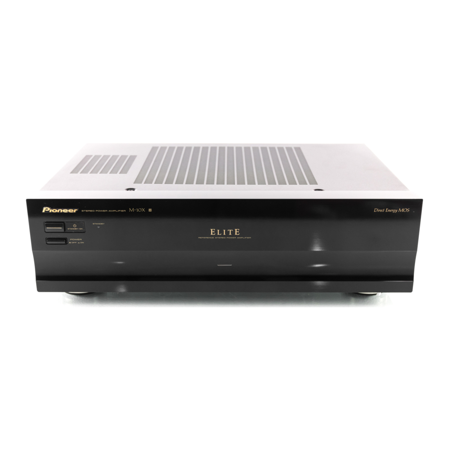
STEREO POWER AMPLIFIER
M-10X
THIS MANUAL IS APPLICABLE TO THE FOLLOWING MODEL(S) AND TYPE(S).
Model
Type
M-10X
KU/CA
MY
CONTENTS
1. SAFETY INFORMATION .................................... 2
2. EXPLODED VIEWS AND PARTS LIST ............. 3
......................................................... 6
4. PCB CONNECTION DIAGRAM ....................... 12
5. PCB PARTS LIST ............................................. 16
6. ADJUSTMENT .................................................. 19
PIONEER CORPORATION
PIONEER ELECTRONICS SERVICE, INC. P.O. Box 1760, Long Beach, CA 90801-1760, U.S.A.
PIONEER EUROPE NV Haven 1087, Keetberglaan 1, 9120 Melsele, Belgium
PIONEER ELECTRONICS ASIACENTRE PTE. LTD. 253 Alexandra Road, #04-01, Singapore 159936
PIONEER CORPORATION 2000
POWER
The illustration shows the KU/CA type
Power Requirement
AC120V
AC220-230V
4-1, Meguro 1-chome, Meguro-ku, Tokyo 153-8654, Japan
v¿,?m
Î
STEREO POWER AMPLIFIER
STANDBY
STANDBY/ON
OFF
ON
REFERENCE STEREO POWER AMPLIFIER
7. GENERAL INFORMATION .............................. 20
7.1 IC ................................................................ 20
7.2 CIRCUIT DESCRIPTION ........................... 21
8. PANEL FACILITIES AND SPECIFICATIONS
.................................................................... 21
ORDER NO.
RRV2382
Remarks
T-ZZA SEPT. 2000 Printed in Japan
Advertisement
Table of Contents

Related Manuals for Pioneer M-10X


Summary of Contents for Pioneer M-10X
-
Page 1: Table Of Contents
PIONEER CORPORATION 4-1, Meguro 1-chome, Meguro-ku, Tokyo 153-8654, Japan PIONEER ELECTRONICS SERVICE, INC. P.O. Box 1760, Long Beach, CA 90801-1760, U.S.A. PIONEER EUROPE NV Haven 1087, Keetberglaan 1, 9120 Melsele, Belgium PIONEER ELECTRONICS ASIACENTRE PTE. LTD. 253 Alexandra Road, #04-01, Singapore 159936 PIONEER CORPORATION 2000 T–ZZA SEPT. -
Page 2: Safety Information
For the latest information, always consult the current Also test with plug reversed PIONEER Service Manual. A subscription to, or ad- (Using AC adapter ditional copies of, PIONEER Service Manual may be plug as required) obtained at a nominal charge from PIONEER. -
Page 3: Exploded Views And Parts List
Packing Sheet AHG1016 Remote Control Cord PDE1247 Power Cord See Contrast table (2) (2) CONTRAST TABLE M-10X/KU/CA and MY are constructed the same except for the following: Part No. Remarks Mark Symbol and Description KU/CA type MY type Operating Instructions (English) - Page 4 M-10X 2.2 EXTERIOR MY type Only KU/CA type Only MY type Only KU/CA type Only KU/CA type Only...
- Page 5 See Contrast table (2) Locking Card Spacer DEC1908 Fuse Caution Label See Contrast table (2) (2) CONTRAST TABLE M-10X/KU/CA and MY are constructed the same except for the following: Part No. Remarks Mark Symbol and Description KU/CA type MY type...
-
Page 6: Block Diagram And Schematic Diagram
M-10X 3. BLOCK DIAGRAM AND SCHEMATIC DIAGRAM 3.1 BLOCK DIAGRAM AND OVERALL SCHEMATIC DIAGRAM (J4) FRONT R ASSY (AWX7768) LED ASSY (AWX7770) AF ASSY (AWX7776: KU/CA type) (AWX7767: MY type) (J2) DIRECT ENERGY MOS POWER AMP POWER AMP WRLC 29dB JA101 0.7V/50 kΩ... - Page 7 M-10X Note: When ordering service parts, be sure to refer to "EXPLODED VIEWS AND PARTS LIST" or "PCB PARTS LIST". CN701 • NOTE FOR FUSE REPLACEMENT FRONT L ASSY (AWX7766) CAUTION - FOR CONTINUED PROTECTION AGAINST RISK OF FIRE. REPLACE WITH SAME TYPE AND RATINGS OF FUSE.
- Page 8 M-10X 3.2 AF and LED ASSYS CN601 AF ASSY (AWX7776: KU/CA type) (AWX7767: MY type)
- Page 9 M-10X CN803 : Audio Signal Route (L ch) JA401 MY type Only LED ASSY (AWX7770)
- Page 10 M-10X 3.3 AC PRIMARY, POWER SW, FRONT R and FRONT L ASSYS • NOTE FOR FUSE REPLACEMENT CAUTION - FOR CONTINUED PROTECTION AGAINST RISK OF FIRE. REPLACE WITH SAME TYPE AND RATINGS OF FUSE. AC PRIMARY ASSY 6.3A/125V REK1085 (KU/CA)
- Page 11 M-10X S901: POWER SW MY type POWER SW ASSY (AWX7057) 250V KU/CA type • NOTE FOR FUSE REPLACEMENT CN601 CAUTION - FOR CONTINUED PROTECTION AGAINST RISK OF FIRE. REPLACE WITH SAME TYPE AND RATINGS OF FUSE. CN202 CN701 FRONT L ASSY...
-
Page 12: Pcb Connection Diagram
M-10X Rear 4. PCB CONNECTION AF ASSY DIAGRAM 4.1 AF and LED ASSYS SIDE A To POWER TRANSFORMER CN803 NOTE FOR PCB DIAGRAMS: 1. Part numbers in PCB diagrams match those in the schematic diagrams. 2. A comparison between the main parts of PCB and schematic diagrams is shown below. - Page 13 M-10X Q401 Q406 Q413 Q414 Q451 IC451 IC151 IC452 Q452 IC101 Q409 Q410 Q412 Q411 Q407 Q323 Q408 Q324 Q319 Q101 Q151 Q322 Q104 Q153 VR301 VR302 Q313 Q318 Q309 Q312 Q325 Q334 CN601 IC301 Q301 Q304 Q251 IC251 (ANP7376-A)
- Page 14 M-10X 4.2 AC PRIMARY, POWER SW, FRONT R and FRONT L ASSYS T1 POWER TRANSFORMER MY type KU/CA type Rear SIDE A FRONT L ASSY (ANP7376-A) VR752 VR751 Q701 Q702 Q704 Q703 Q705 Q707 IC751 Q706 Q751 Q752...
- Page 15 M-10X SIDE A AC PRIMARY ASSY POWER SW ASSY KU/CA type NEUTRAL LIVE MY type (ANP7377-A) (ANP7377-A) Q811 IC811 FRONT R ASSY (ANP7377-A) VR601 Q601 Q602 Q603 Q604 Q605 Q610 Q606 Q608 Q609 Q613 Q612 Q611 IC601 IC602 IC603 Q616...
-
Page 16: Pcb Parts List
M-10X 5. PCB PARTS LIST NOTES : ÷ Parts marked by “ NSP ” are generally unavailable because they are not in our Master Spare Parts List. ÷ The mark found on some component parts indicates the importance of the safety factor of the part. - Page 17 M-10X PCB PARTS LIST FOR KU/CA TYPE Mark No. Description Part No. Mark No. Description Part No. POWER SW ASSY AC PRIMARY ASSY SWITCHES AND RELAYS SEMICONDUCTORS S901 ASG1035 IC811 NJM78M56FA Q811 2SK1132 D815 HSS104–02 CAPACITORS D811–D814 S5688G C901 (3300pF/250V)
- Page 18 M-10X Mark No. Description Part No. Mark No. Description Part No. C407 CKCYF223Z50 AF ASSY C310, C327, C409, C453, C454 CKCYF473Z50 C307, C308 (220µF/25V) PCH1128 SEMICONDUCTORS IC451 NJM78M15FA RESISTORS IC452 NJM79L15A R363, R364 RD1/2PMF152J IC301 UPC4570C R458, R459 RD1/4LMF2R2J Q152, Q327, Q328, Q409, Q410 2SA1048 R317, R318, R351–R354, R417...
-
Page 19: Adjustment
M-10X 6. ADJUSTMENT 6.1 IDLE CURRENT ADJUSTMENT CAUTION : Heatsinks’ (Q323–Q326) DC level is equal to +B or –B. Don’t touch them or you will be electricary chocked. 1. Connect the measuring instrument as Fig.6–1. (R415 or R416) 2. Set VR301 and VR302 to minimum. -
Page 20: General Information
M-10X 7. GENERAL INFORMATION • The information shown in the list is basic information and may not correspond exactly to that shown in the schematic diagrams. 7.1 IC PD5604A ( IC601: FRONT R ASSY) Remote Control Amp Microcomputer Pin Assignment (Top view) -
Page 21: Circuit Description
M-10X 7.2 CIRCUIT DESCRIPTION Use a wide range linear circuit of A-607R series for voltage stage, and use HEX POWER MOS- FET for output stage. This circuitry eliminates source resistance, and reduce power loss in large amount with super low capacity resistor of output stage device and realize the low generation of heat, low source voltage. -
Page 22: Specifications
M-10X SPECIFICATIONS For MY Type For KU/CA Type Amplifier Section Amplifier Section Continuous power output Continuous average power output of 100 (both channels driven at 20 Hz to 20 kHz)* watts* per channel, min., at 4 ohms, from 20 T.H.D. 0.09 %, 4 Ω ..........90 W + 90 W Hz to 20,000 Hz with no more than 0.2 %**...