
Related Manuals for NEC RIH-2667


Summary of Contents for NEC RIH-2667
-
Page 1: User Manual
Inverter Split (room) air conditioner RIH-2667 RIH-3267 User Manual PDF created with pdfFactory Pro trial version www.pdffactory.com... -
Page 2: Table Of Contents
Inverter Split (Room) Air Conditioner Preparation before use Safety Precautions Identification of parts Indoor unit Outdoor unit Operating and display Remote controller Operation instructions Operation modes Air flow direction control Smart mode Timer mode Sleep mode Super mode Maintenance Protection... -
Page 3: Preparation Before Use
Note: If the air conditioner you purchased is a Cooling Only one, but you preset the remote controller as Heat Pump, it will not operate. But if the air conditioner you purchased is a Heat Pump one, and you preset the remote controller as Cooling Only, then you CAN NOT preset the Heating operation with the remote controller. -
Page 4: Safety Precautions
Safety precautions Symbols in this User Manual are interpreted as shown below. Be sure not to do. Pay attention to such a situation. Use correct power supply in accordance with the rating plate requirement. Otherwise, serious faults or hazard may occur or a fire maybe break out. -
Page 5: Identification Of Parts
The figures in this manual are based on the external view of a standard model. Consequently, the shape may differ from that of the air conditioner you have selected. Note: The pipes and power connection cord will be provided or purchased by customer. -
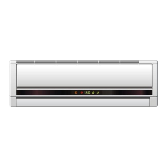
Page 6: Operating And Display
Identification of parts UH series operating and display Timer Indicator It lights up during the set time. Timer Comp. Compressor indicator It lights up when compressor is running. The shape and position of the switches and indicators may vary from different models, but their function are similar. PDF created with pdfFactory Pro trial version Run Indicator It is on during operation. -
Page 7: Remote Controller
Remote controller Remote controller The remote controller transmits signals to the system. S UP ER Indication symbols on LCD: Note: Each mode and relevant function will be further specified in following pages. PDF created with pdfFactory Pro trial version ON/OFF BUTTON ... - Page 8 Note: The remote controller holder is an optional part. Remote controller holder How to Use To operate the room air conditioner, aim the remote controller to the signal receptor. The remote controller will operate the air conditioner at a distance of up to 7m when pointing at signal receptor of indoor unit.
-
Page 9: Operation Instructions
Each time MODE button is pressed, the operation mode is changed in sequence: COOLING Heating mode is NOT available for cooling only air conditioner. FAN mode Each time the "FAN" button is pressed, the fan speed is changed in sequence: Auto High At "FAN ONLY"... -
Page 10: Airflow Direction Control
Note: The shape of the unit may look different from that of the air conditioner you have selected. Do not turn the vertical adjustment louvers manually, otherwise malfunction may occur. If that happens, turn off the unit first and cut off the power supply, then restore power supply again. -
Page 11: Smart Mode
Operation instructions SMART mode Press the SMART button, the unit enters smart mode(fuzzy logic operation) directly regardless of the unit is on or off. In this mode, temperature and fan speed are automatically set based on the actual room temperature. Operation mode and temperature are determined by indoor temperature Heat pump models Indoor temperature... -
Page 12: Timer Mode
Operation instructions Timer mode It is convenient to set the timer on with to achieve a comfortable room temperature at the time you get home. You can also set timer off at night to enjoy a good sleep. Setting a switch-on timer when the appliance is off. -
Page 13: Sleep Mode
3 hours constantly, then keeps steady. *Note: In cooling mode, if room temperature is 26 or above, set temperature will not change. Note: Heating is NOT available for cooling only air conditioner. SUPER mode SUPER mode is used to start or stop fast cooling. -
Page 14: Maintenance
If the dirt is conspicuous, wash it with a solution of detergent in lukewarm water. After cleaning, dry well in shade. Close the front panel again. Clean the air filter every two weeks if the air conditioner operates in an extremely dusty environment. -
Page 15: Protection
Room temperature is below 18 c Room temperature is below 18 c If the air conditioner runs in COOLING or DRY mode with door or window opened for a long time when relative humidity is above 80%,dew may drip down from the outlet. -
Page 16: Troubleshooting
Caused by the flow of refrigerant in the air conditioner, not a trouble. Defrosting sound in heating mode. The sound may be generated by the expansion or contraction of the front panel due to change of temperature. -
Page 17: Installation Instructions
Installation instructions Installation diagram Distance from wall should be over 50mm Air intake distance from the wall should be over 250mm Above figure is only a simple presentation of the unit, it may not match the external appearance of the unit you purchased. Installation must be performed in accordance with the national wiring standards by authorized personnel only. -
Page 18: Select The Installation Locations
Installation instructions Location for Installing Indoor Unit Where there is no obstacle near the air outlet and air can be easily blown to every corner. Where piping and wall hole can be easily arranged. Keep the required space from the unit to the ceiling and wall according to the installation diagram on previous page. -
Page 19: Indoor Unit Installation
Installation instructions Indoor unit installation 1. Installing the Mounting Plate Decide an installing location for the mounting plate according to the indoor unit location and piping direction. Keep the mounting plate horizontally with a horizontal ruler or dropping line. Drill holes of 32mm in depth on the wall for fixing the plate. Insert the plastic plugs to the hole, fix the mounting plate with tapping screws. - Page 20 Installation instructions Piping Joints Thermal Insulation: Wrap the piping joints with thermal insulation materials and then wrap with a vinyl tape. Piping Thermal Insulation: a. Place the drain hose under the piping. b. Insulation material uses polythene foam over 6mm in thickness. Note: Drain hose is prepared by user.
- Page 21 Caution: Caution: 1. Never fail to have an individual power circuit specifically for the air conditioner. As for the method of 1. Never fail to have an individual power circuit specifically for the air conditioner. As for the method of 1.
- Page 22 Installation instructions Installation instructions Wiring Diagram Wiring Diagram Make sure that the color of wires of the outdoor unit and the terminal No. are the same as those Make sure that the color of wires of the outdoor unit and the terminal No. are the same as those of the indoor unit.
-
Page 23: Outdoor Unit Installation
Installation instructions Outdoor unit installation 1.Install Drain Port and Drain Hose (for heat-pump model only) The condensate drains from the outdoor unit when the unit operates in heating mode. In order not to disturb your neighbor and protect the environment, install a drain port and a drain hose to direct the condensate water. -
Page 24: Notes
Input or use other over-current protective device instead. Only the air conditioner can be connected to the power line. The power connection for the air conditioner has to be done at the main power distribution which has to be of a low impedance. - Page 25 For Service in outer areas, please contact your For Service in outer areas, please contact your For Service in outer areas, please contact your of the nearest Authorized NEC Service Centre. of the nearest Authorized NEC Service Centre. of the nearest Authorized NEC Service Centre.