
Related Manuals for Hitachi DH 20PB


Summary of Contents for Hitachi DH 20PB
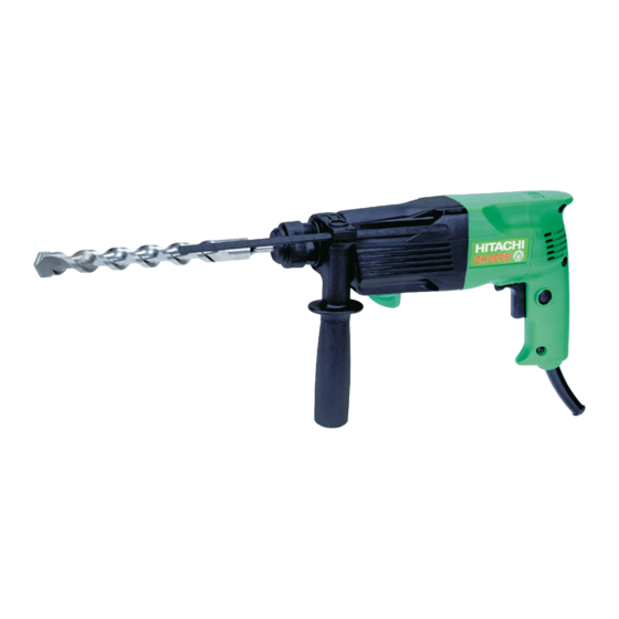
- Page 1 MODELS DH 20PB POWER TOOLS TECHNICAL DATA HAMMER DRILL DH 20PB SERVICE MANUAL LIST No. E462 Feb. 2002 SPECIFICATIONS AND PARTS ARE SUBJECT TO CHANGE FOR IMPROVEMENT...
- Page 2 REMARK: Throughout this TECHNICAL DATA AND SERVICE MANUAL, a symbol(s) is(are) used in the place of company name(s) and model name(s) of our competitor(s). The symbol(s) utilized here is(are) as follows: Competitors Symbols Utilized Model Name Company Name GBH2-20SRE BOSCH...
-
Page 3: Table Of Contents
9-4. Tightening Torque ........................20 9-5. Wiring Diagram ..........................20 9-6. Internal Wire Arrangement and Wiring Work ................21 9-7.Insulation Tests ..........................22 9-8.No-load Current Values ........................ 22 10. STANDARD REPAIR TIME (UNIT) SCHEDULES ..............23 Assembly Diagram for DH 20PB... -
Page 4: Product Name
Thanks to the newly provided powerful motor, the Model DH 20PB has 20-mm drilling capacity (in concrete) and the drilling speed is far faster than the competitors. The Model DH 20PB is an excellent cost/ performance hammer drill expected to expand our market share. -
Page 5: Selling Points
(2) Fast drilling speed The drilling speed of the Model DH 20PB is 40% faster than B (10% slower than the Model DH 24PB) as the Model DH 20PB has great striking energy owing to the optimally designed rotation speed, striking frequency and weight of the striker. -
Page 6: Specifications
5. SPECIFICATIONS 5-1. Specifications Model DH 20PB Capacity Concrete 3.4 -- - 20 mm (1/8" -- - 13/16") Steel 13 mm (1/2") Wood 32 mm (1-1/4") Power source AC single phase 50 Hz or 60 Hz Voltage (V) Voltage, current and input... -
Page 7: Optional Accessories
5-2. Optional Accessories A. Drilling anchor holes (rotation + striking) Drill bit (slender shaft) (1) Drill bit (slender shaft) (2) Adapter for slender shaft (SDS-plus shank) Drill bit (slender shaft) Adapter for slender shaft Outer dia. (mm) Code No. Code No. Effective length (mm) Overall length (mm) 3.4 (1/8") - Page 8 B. Anchor setting Anchor setting bar to permit anchor setting operation with the hammer drill Anchor setting bar Anchor setting adapter (SDS-plus shank) Part name Part name Overall length Code No. Overall length Code No. 302976 302979 W - 1/4 anchor setting adapter - A W - 1/4 anchor setting adapter - B 302975 302978...
- Page 9 (2) Guide plate Core bit (outer diameter) (mm) Code No. Core bit (outer diameter) Code No. 32 (1-1/4") 982686 982690 50 (2") 35 (1-3/8") 982687 38 (1-1/2") 982688 45 (1-25/32") 982689 (3) Core bit with guide plate (The guide plate is not equipped with core bit with outer diameter of 25 mm (31/32") and 29 mm (1-5/32").) Outer diameter (mm) Code No.
- Page 10 F. Drilling hole and driving screw (rotation only) Drill chuck, chuck adapter (G), special screw and chuck wrench Special screw Chuck adapter (G) 13 mm (1/2") Drill chuck (SDS-plus shank) (13VLR type) (Note) If the tool is to be used for loosening screws, open the three jaws of the drill chuck and securely fix the drill chuck to the chuck adapter (G) with the special screw (a left-hand threaded M6 screw) when Chuck wrench...
- Page 11 G. Driving screws (rotation only) For drilling holes in steel and wood • • • • Chuck adapter (D) Drill chuck Chuck wrench (SDS-plus shank) (13VLA) (NOTE) The 13VLA drill chuck and chuck adapter (D) cannot be used for reverse rotation. If reverse rotation is to be used for loosening screws, use the plus bit (Bit No.
-
Page 12: Comparisons With Similar Products
Drilling speed depends on the operating conditions. The test results shown in Fig. 1 are based on actual factory tests, and are used as a reference only. Fig. 1 shows the drilling speed comparisons for downward drilling. The drill bits used are the Hitachi genuine SDS-plus shank bits. 1000... -
Page 13: Precautions In Sales Promotion
7. PRECAUTIONS IN SALES PROMOTION In the interest of promoting the safest and most efficient use of the Model DH 20PB Hammer Drill by all of our customers, it is very important that at the time of sales the salesperson carefully ensures that the buyer seriously recognizes the importance of the contents of the Handling Instructions, and fully understands the meaning of the precautions listed on the Caution Plate attached to each tool. - Page 14 Accordingly, the armature shaft and the cylinder axis are at a right angle to each other. In the Model DH 20PB through adoption of a spiral drive system (a mechanism using a reciprocating bearing), a more compact design has been achieved by arranging the armature shaft in parallel with the cylinder axis.
- Page 15 Idle striking prevention mechanism The idle striking prevention mechanism in the Model DH 20PB is different from that of conventional hammer drills. When the drill bit is lifted from the concrete surface on completion of drilling, the second hammer moves to the position indicated by the continuous lines in Fig.
-
Page 16: Rotation Only" And "Rotation + Striking" Changeover Mechanism
Slip mechanism The slip mechanism in the Model DH 20PB consists of a coil spring which applies a pre-set amount of pressure to ensure the interlocking of three claws provided on the flange of the cylinder (the final rotating shaft) and three matching claws provided on the face of the second gear, by which rotation is transmitted to the cylinder. -
Page 17: Rotation Only" (No Striking)
8-4. "Rotation Only" (no striking) Turn the change lever fully clockwise to the "drill" mark position to obtain "Rotation Only" function. To use the tool for drilling or driving screws, the chuck adapter and a drill chuck (optional accessories) must be used. In older models such as the Models DH 22 and DH 22V, when the chuck adapter is mounted the second hammer moves forward, the striker slips out of striking position to open up an air vent and stop striking operation and "Rotation Only"... -
Page 18: Drill Bits
8-5. Drill Bits The chuck section is designed exclusively for the popular and widely available SDS-plus shank bits, as shown in Fig. 4. Rotating torque is transmitted to the drill bit by two key rails provided in the tool holding section. A steel ball is used to prevent the bit from falling out. -
Page 19: Chuck Section
8-6. Chuck Section Fig. 6 shows the construction of the chuck section. Steel ball Washer (B) Front cap Grip Holder spring Forward Backward Key rails Cylinder (two pieces) Ball holder Fig. 6 The opening where the drill bit is inserted is covered with a front cap (rubber) to prevent dust from entering inside. When the drill bit is inserted, the steel ball fits into the matching groove on the drill bit to lock it in place and prevent it from falling out . - Page 20 Approx. 72 mm (2-27/32") Approx. 16 mm (5/8") Grip (on the main body side) Drill bit length: 166 mm Drill bit length: 110 mm Socket adapter (B) Socket Seal cover Retaining ring for D30 shaft Dust cover Outer race Washer D6.35 steel ball Fig.
-
Page 21: Precautions In Disassembly And Reassembly
9. PRECAUTIONS IN DISASSEMBLY AND REASSEMBLY The [Bold] numbers in the descriptions below correspond to the item numbers in the Parts List and exploded assembly diagram. 9-1. Disassembly (1) Disassembly of the Striking Mechanism Section With a drill bit or screwdriver bit, push in the Second Hammer [25] to release the Striker [28] from the O-Ring (I.D.10.5) [27]. - Page 22 (3) Disassembly of the cylinder, second gear (slip mechanism section) and related parts Take the Inner Cover [33] off from the Gear Cover [7] and remove the entire chuck section. Extract the Retaining Ring for D20 Shaft [6]. (For easy removal of this retaining ring, use of Special Repair Tool J-200 Snap Ring Pliers [Code No.
-
Page 23: Reassembly
9-2. Reassembly Perform reassembly in the reverse order of disassembly while observing the given precautions and taking care of the following points. (1) To make reassembly easier, coat grease on the Steel Balls [11], [18], [19]. (2) Reassembly of the Change Lever [13] With a flat-blade screwdriver or similar tool, move the Clutch [38] and the Reciprocating Bearing [40] so that the claw (protruding portion) of the Reciprocating Bearing [40] and the claw (protruding portion) of the Clutch [38] are in contact. -
Page 24: Internal Wire Arrangement And Wiring Work
9-6. Internal Wire Arrangement and Wiring Work Put the lead wires from the Stator [49] under the Brush Holder [63] Brush Terminal Choke Coil Carbon Brush [62] Brown (from the Carbon Brush [62]) Gray (from the Stator [49]) Black (from the Stator [49]) Red (from the Stator [49]) -
Page 25: 9-7.Insulation Tests
(Cord) the windows near the terminals and pull out the lead Fig. 15 Wiring of speed control switch (DH 20PB) wires. 9-7.Insulation Tests On completion of reassembly after repair, measure the insulation resistance and conduct the dielectric strength test. -
Page 26: Standard Repair Time (Unit) Schedules
10. STANDARD REPAIR TIME (UNIT) SCHEDULES Variable 60 min. MODEL Fixed Work Flow DH 20PB Housing Stator Switch Armature Ass'y Cord Inner Cover O-Ring Ball Bearing (608DD) Washer (A) x2 Ball Bearing (608VV) General Assembly Change Lever Front Cap Retaining Ring... - Page 27 LIST NO. E462 ELECTRIC TOOL PARTS LIST HAMMER DRILL 2002 • • Model DH 20PB (E1)
- Page 28 PARTS DH20PB ITEM CODE NO. DESCRIPTION REMARKS USED 306-345 FRONT CAP 306-992 GRIP 306-343 BALL HOLDER 306-342 HOLDER SPRING 984-118 WASHER (B) 939-547 RETAINING RING FOR D20 SHAFT (10 PCS.) 314-876 GEAR COVER 301-654 TAPPING SCREW (W/FLANGE) D5X35 314-881 O-RING 981-328 SPRING (H) 959-155...
- Page 29 NOISE SUPPRESSOR 302-488 EARTH TERMINAL 999-041 CARBON BRUSH (1 PAIR) 999-072 CARBON BRUSH (AUTO STOP TYPE) (1 PAIR) 955-203 BRUSH HOLDER HITACHI LABEL 981-373 TUBE (D) FOR CORD 315-147 DUST PACKING 314-922 CHOKE COIL (A) BLUE 314-923 CHOKE COIL (A) BROWN...
- Page 30 STANDARD ACCESSORIES DH20PB ITEM CODE NO. DESCRIPTION REMARKS USED 307-786 CASE 303-659 SIDE HANDLE 303-709 DEPTH GAUGE OPTIONAL ACCESSORIES ITEM CODE NO. DESCRIPTION REMARKS USED 306-369 DRILL BIT (SLENDER SHAFT) D3.4X90 306-368 DRILL BIT (SLENDER SHAFT) D3.5X90 306-370 ADAPTER FOR SLENDER SHAFT (SDS PLUS) 944-460 TAPER SHANK DRILL BIT D11X100 944-461...
- Page 31 DH20PB OPTIONAL ACCESSORIES ITEM CODE NO. DESCRIPTION REMARKS USED 971-799 ANCHOR SETTING ADAPTER B W1/4" (MANUAL) 971-800 ANCHOR SETTING ADAPTER B W5/16" (MANUAL) 971-801 ANCHOR SETTING ADAPTER B W3/8" (MANUAL) 971-802 ANCHOR SETTING ADAPTER B W1/2" (MANUAL) 971-803 ANCHOR SETTING ADAPTER B W5/8" (MANUAL) 982-684 CENTER PIN (A) 109L FOR CORE BIT D32-38 982-685...
- Page 32 DH20PB ITEM CODE NO. DESCRIPTION REMARKS USED - - - 6 - - - Printed in Japan 2 -- 02 (020205N)