Table of Contents
Advertisement
Advertisement
Table of Contents
Troubleshooting

Related Manuals for LG LMXS30776S


Summary of Contents for LG LMXS30776S
- Page 1 - 1 -...
-
Page 2: Table Of Contents
SAFETY PRECATUTIONSS ..............................2 1. SPECIFICATIONS ................................3 2. PARTS IDENTIFICATION ..............................4 3. DISASSEMBLY................................5-29 REMOVING AND REPALCING REFRIGERATOR DOORS ....................5 DOOR ....................................6-7 SUB, PCB ....................................8 DOOR ALIGNMENT ................................9 FAN AND FAN MOTOR ..............................9-10 REFRIGERATOR LIGHT (TOP) ............................11-12 MULTI DUCT .................................. -
Page 3: Specifications
1. SPECIFICATIONS 1-1 LMXS30776S 30 cu.ft. ITEMS SPECIFICATIONS ITEMS SPECIFICATIONS DOOR DESIGN Side Rounded VEGETABLE TRAY Clear Drawer Type DIMENSIONS (inches) 3 /4 X 38 1 /8 X 70 1 /4 (WXDXH) 30cu.ft. COMPRESSOR Linear NET WEIGHT (pounds) 180kg(397lb) EVAPORATOR... -
Page 4: Parts Identification
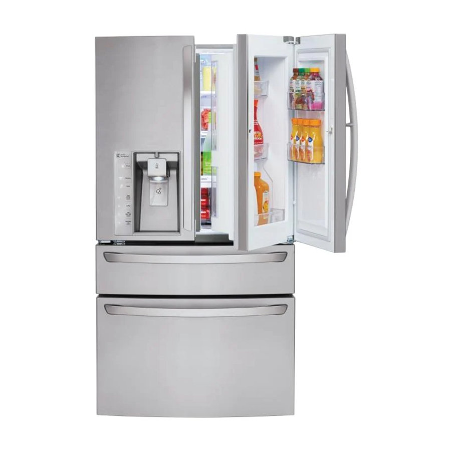
2. PARTS IDENTIFICATION Adjustable Refrigerator Shelf LED interior lamps Door-In-Door Case Cheese & Butter Bin Indoor Ice Bin Condiment Bin Crisper EasyReach™ Custom Chill™ Drawer Pullout Drawer Durabase® and Durabase® Divider - 4 -... -
Page 5: Disassembly
3. DISASSEMBLY 3-1 REMOVING AND REPLACING REFRIGERATOR DOORS - 5 -... -
Page 6: Door
- 6 -... - Page 7 - 7 -...
-
Page 8: Sub, Pcb
3-3 Sub, PCB - 8 -... -
Page 9: Door Alignment
3-4 Door Alignment 3-5 FAN AND FAN MOTOR - 9 -... - Page 10 - 10 -...
-
Page 11: Refrigerator Light (Top)
3-6 Refrigerator Light (Top) - 11 -... -
Page 12: Multi Duct
3-7 MULTI DUCT - 12 -... -
Page 13: Dispenser
3-8 DISPENSER 3-10 CustomChill DISPLAY 3-9 DISPLAY PCB - 13 -... -
Page 14: Ice Button Assembly
3-11 ICE BUttoN ASSEMBLY 3-12 WATER BUTTON ASSEMBLY 3-13 ICE CORNER DOOR REPLACEMENT - 14 -... -
Page 15: Icemaker Replacement
3-14 ICEMAKER REPLACEMENT 3-15 SUB PCB FOR WORKING DISPENSER - 15 -... -
Page 16: Cap Duct Motor Replacement
3-16 CAP DUCT MOTOR REPLACEMENT 3-17 Module filter Replacement ① ② ③ → → - 16 -... -
Page 17: Module Filter Part Repalcement
3-18 Module filter Part Replacement 3-19 HOW TO REMOVE A ICEBIN 3-20 HOW TO INSERT A ICE BIN - 17 -... -
Page 18: Customchill Drawer
3-21 CustomChill Drawer - 18 -... - Page 19 - 19 -...
- Page 20 - 20 -...
- Page 21 - 21 -...
-
Page 22: Hot To Remove And Reinstall The Pullout Drawer
- 22 -... - Page 23 - 23 -...
-
Page 24: Water Valve Disassembly Method
3-23 WATER VALVE DISASSEMBLY METHOD 3-24 Fan motor assembly disassembly method - 24 -... -
Page 25: Caution : Sealed System Repair
3-25 CAUTION : Sealed System Repair 3-26 Way Valve Service... -
Page 26: How To Remove And Reinstall The Homebar
3-27 HOW TO REMOVE AND REINSTALL THE HOMEBAR - 26 -... -
Page 27: How To Remove And Reinstall Thehomebar Door
3-28 HOW TO REMOVE AND REINSTALL THE HOMEBAR DOOR - 27 -... -
Page 28: How To Remove And Reinstall The Door Foam Assembly, Refrigerator
3-29 HOW TO REMOVE AND REINSTALL THE DOOR FOAM ASSEMBLY, REFRIGERATOR - 28 -... -
Page 29: How To Remove Frame Door Switch Of Door Foam
3-30 HOW TO REMOVE FRAME DOOR SWITCH OF DOOR FOAM - 29 -... -
Page 30: Adjustment
4-1 COMPRESSOR 4-2-3 Compressor protection logic 4-1-1 Role 4-1-2 Notes for Usage 4-1-3 Remove the cover PTC (1) Remove the Cover Back M/C (2) Remove two screws on comp base (3) Use a L-shaped flap tooll to pry off the cover (4) Assembly in reverse order of disassembly - 30 -... -
Page 31: Circuit Diagram
- 31 -... -
Page 32: Troubleshooting
Ice Type When checking Resistance values, make sure to R efrigerator turn off the power, and wait for the voltage to Freezer discharge. Fresh Auto Air Filter Power F i l ter Reset Hold 3s ec Within 3 hours after the error : Press the Ice Plus button and Freezer button simultaneousl Ice Plus All errors, except for “E rt”, “E SS”, “E HS”, “E IS(except for Icing sensor)”. - Page 33 - 33 -...
-
Page 34: Pcb Picture
7. PCB PICTURE 7-1 Main PCb EBR78643401) 7-2 Display PCB - 34 -... - Page 35 7-3 Sub PCB - 35 -...
-
Page 36: Troubleshooting With Error Display
8. Troubleshooting With Error Display 8-1 Freezer Sensor Error (E FS) ℉ ℃ ℉ ℃ ℉ ℃ ℉ ℃ ℉ ℃ ℉ ℃ - 36 -... - Page 37 - 37 -...
- Page 38 8-2 Refrigerator Sensor Error (E rS) ℉ ℃ ℉ ℃ ℉ ℃ ℉ ℃ ℉ ℃ - 38 -...
- Page 39 - 39 -...
- Page 40 8-3 Icing Sensor Error (E IS) ℉ ℃ ℉ ℃ ℉ ℃ ℉ ℃ ℉ ℃ ℉ ℃ ℉ ℃ - 40 -...
- Page 41 - 41 -...
- Page 42 8-4 Defrist Sensor Error (F dS) ℉ ℃ ℉ ℃ ℉ ℃ ℉ ℃ ℉ ℃ - 42 -...
- Page 43 - 43 -...
- Page 44 8-5 Defrost Sensor Error (r dS) ℉ ℃ ℉ ℃ ℉ ℃ ℉ ℃ ℉ ℃ - 44 -...
- Page 45 - 45 -...
- Page 46 8-6 Defrost Heater Error (F dH) - 46 -...
- Page 47 - 47 -...
- Page 48 8-7 Defrost Heater Error (r dH) - 48 -...
- Page 49 - 49 -...
- Page 50 8-8 Refrigerator Fan Error (E rF) - 50 -...
- Page 51 - 51 -...
- Page 52 8-9 Freezer Fan Error (E FF) - 52 -...
- Page 53 - 53 -...
- Page 54 8-10 Icing Fan Error (E IF) - 54 -...
- Page 55 - 55 -...
- Page 56 8-11 Condenser Fan Error (E CF) - 56 -...
- Page 57 - 57 -...
- Page 58 8-12 Communication Error (E CO) - 58 -...
- Page 59 - 59 -...
- Page 60 8-13 Cube mode doesn’t work - 60 -...
- Page 61 - 61 -...
- Page 62 - 62 -...
- Page 63 8-14 Crush mode doesn’t work - 63 -...
- Page 64 - 64 -...
- Page 65 - 65 -...
- Page 66 8-15 Water mode doesn’t work - 66 -...
- Page 67 - 67 -...
- Page 68 8-18 Middle room lamp doesn’t work - 68 -...
- Page 69 - 69 -...
- Page 70 8-17 Freezer room lamp doesn’t work - 70 -...
- Page 71 - 71 -...
- Page 72 8-18 Refrigerator room lamp doesn’t work - 72 -...
- Page 73 - 73 -...
- Page 74 8-19 Roop cooling in Fresh food section - 74 -...
- Page 75 - 75 -...
- Page 76 8-20 Poor cooling In Freezer compartment - 76 -...
- Page 77 - 77 -...
- Page 78 - 78 -...
-
Page 79: Reference
10. Reference 10-1 TEST MODE and Removing TPA - 79 -... - Page 80 10-2 TEMPERATURE CHART - FREEZER AND ICING SENSOR - 80 -...
- Page 81 10-3 TEMPERATURE CHART - REFRIGERATOR AND DEFROST SENSOR - 81 -...
- Page 82 10-4 How to check the Fan-Error - 82 -...
-
Page 83: Component Testing Information
11. COMPONENT TESTING INFORMATION 11-1 Defrost Seneor of Defrost heater (F/R) - 83 -... - Page 84 11-2 Sheath Heater (Freezer Room) - 84 -...
- Page 85 11-3 Sheath Heater (Refrigerator Room) - 85 -...
- Page 86 11-4 Door Switch, H Function How to <Switch, Refrigerator> Measure Button (Plunger) Beep Standard Multimeter beep – Switch,R - 86 -...
- Page 87 11-5 Door Switch, F Function How to No magnet Magnet near the Switch Measure magnet Magnet must be center of Switch Magnet Center Magnet Center Switch Center Switch Center Bad position Good position Standard - 87 -...
- Page 88 11-6 Dispenser DC Motor - 88 -...
- Page 89 11-7 AC Motor ASSEMBLY - 89 -...
- Page 90 11-8 Damper Function How to Measure < Damper Circuit > Blue Blue White White Check the 3 Yellow < extension > Check the Check the Standard Damper - 90 -...
- Page 91 11-9 Lamp Socket Function How to Measure Standard - 91 -...
- Page 92 11-10 Flow Sensor Function How to Measure Standard - 92 -...
-
Page 93: Compressor Troubleshooting
12. Compressor Troubleshooting - 93 -... - Page 94 12-1 Check A - 94 -...
- Page 95 - 95 -...
- Page 96 12-2 Check B B1. LED blinks once, then repeats (FCT0 Fault) Protection Logi c Blink OFF Blink OF F - Purpose : Detecting motor current and voltage error - Check voltage at point A (Motor Voltage), point B (Motor Current) and Point C (Capacitor Voltage) when compressor is off.
- Page 97 B3. LED blinks three times, then repeats (Stroke Trip) B4. LED blinks five times, then repeats (Locked Piston) B5. LED blinks six times, then repeats (Current Trip) - 97 -...
- Page 98 B6. LED blinks seven times, then repeats n i l n i l n i l n i l n i l n i l n i l - Purpos e: P revent high current due to IPM S hort - Caus e: Damaged IPM (Dead Short) - Test for a dead short at P oint A with a V OM.
- Page 99 12-3 Check C - 99 -...
- Page 100 12- 4 Check D D1. Activate Protection logic Cycle check with protection logic Sealed system D2. sealed system diagnosis - 100 -...
- Page 101 - 101 -...
- Page 102 LED operating condition Cause Service guideline LED two - time repetiton (Stroke Trip) - off - - off - - off repeating LED five - time repetiton (Piston Lock Trip) - off - - off repeating LED six - time repetiton (Current Trip) - off - - off repeating...
- Page 103 12- 5 SERVICE DIAGNOSIS CHART COMPLAINT POINTS TO BE CHECKED REMEDY Warm position. Recommended position. Recommended position. colder position. Warm position. - 103 -...
- Page 104 12- 6 REFRIGERATORION CYCLE Troubleshooting Chart TEMPERATURE STATE OF STATE OF THE OF THE CAUSE REMARKS THE UNIT EVAPORATOR COMPRESSOR 12-6-1 Cleaning - 104 -...
- Page 105 12-6-2 SEALED SYSTEM DIAGNOSIS “Not Cooling” Complaint All components operating, No airflow problems, Not frosted up as a defrost problem problem has been isolated to sealed system area Frost Partial None Pattern? Equalization Equalization Test Test Very Fast Very Slow Very Slow Very Fast Fast...
-
Page 106: Icemaker Operationg Method And Trouble Shooting
- 106 -... - Page 107 13-2 ICEMAKER FUNCTIONS 13-2-1Icemaking mode 13-2-2 Harvest mode 13-2-3 Fill/Park Position 13-3 Trouble Shooting Ice & Water System Issues 13-3-1 Icemaker not making ice or not making enough ice (Environmental Diagnosis) No making ice saddle valve. Water fill tube heater Is Icemaker’s tray filled all the water valve’...
- Page 108 13-3-2 Icemaker not making ice or not making enough ice (Icemaker Unit & Ice-detecting sensor Diagnosis) - 108 -...
- Page 109 STEP (Ice-detecting sensor Diagnosis) 2. Close the left door 1. Remove Ice bin from compartment 3. Wait for 3min. (Door switch pushed) 4. Freezer door stays open Ice Type Refrigerator 5. Push the refrigerator Freezer button & lock button at the same time.
-
Page 110: Description Of Function & Circuit Of Micom
14-1-1 Function 14-1-2 How to Toggle the Display between °D & °C 14-1-3 Lock function (dispenser and display button lock) - 110 -... - Page 111 14-1-4 Filter condition display function 14-1-5 Air Filter selection 14-1-6 Ice Plus selection 14-1-7 Dispenser Use selection - 111 -...
- Page 112 14-1-8 CONTROL OF FREEZER FAN MOTOR 2. When refrigerator is overloaded, fan motor runs in high speed as powered-up Standard speeds is used for general purposes. 3. To improve cooling speed, the RPM of freezer fan motor changes from normal speed to high. 14-1-9 Cooling Fan Motor 14-1-10 Ice Compartment Fan 14-1-11 Refrigeration room Fan Motor...
- Page 113 14-1-14 Defrosting (removing frost) For initial power on or for restoring power, defrosting starts when the compressor running time reaches 4 hours. 8-1-15. 14-1-15 Defect Diagnosis Function plus - 113 -...
-
Page 114: Exploded View & Replacement Parts List
15. EXPLODED VIEW & REPLACEMENT PARTS LIST 405J 207B 158C 402A 500P 503D 409D 158A 103B 271B 610F 409F 103A 502A 282G 207A 282H 402A 120A 406D 610D 628A 409H 631C 405E 327B 271D 500A 332D 404C 145B 605A 411A 249M 145A 313A... -
Page 115: Customchill Parts
205D 150A 264B 150F 150E 264A 264B 264A 136C 150F... -
Page 116: Freezer Parts
145G 145C 145I 145K 136B 145F 145M 133C 132Q 145J 136E 133C 145H 134A 205D 132P 150B 237C 150D 150C 136A 253D... -
Page 117: Refrigerator Parts
REFRIGERATOR PARTS CAUTION: Use the part number to order part, not the position number. 141H 142C 141A 142A 142B 142D 141F 141B 141H 141H 141A 141A 141F 141F 141B 141B 255A 255B 154D 144A 177C 177E 132P 255A 162A 146E 141D 132S 161B... -
Page 118: Door Parts
205H 180A 207D 231B 233B 235A 500C 241K 250W 232A 281K 312F 241K 241B 241K 312G 241B 281B 207C 146F 281K 312E 241A 243C 624A 262E 262C 244A 243B 619C 205F 619B 312B 402B 233A 180A 624C 231A 615A 624G 233H 250E 405M... - Page 119 276A 276G 276F 276I 405A 276B 275A 278C 279A 278D 279K 402E 402C 279L 501D 279B 281A 501A 279C...
-
Page 120: Valve/Water Tube Parts
617A 616G 603C 623B 616G 616J 623B 616J 616F 603C 627B 627A 619A 603B... - Page 121 630J 630J 612A 630F 630B 630C 600A 611A 607A 630A 630H 630D 606A 630E 630Q 630G...
- Page 122 P/No. MFL62188124 DEC., 2014 Printed in Korea...