Table of Contents
Advertisement
Quick Links
Advertisement
Table of Contents

Related Manuals for Motorola XTNI Non-display Model


Summary of Contents for Motorola XTNI Non-display Model
- Page 2 Motorola, the Stylized M Logo, and all other trademarks indicated as such herein are Trademarks of Motorola, Inc. Reg. U.S. Pat. & Tm. Off. © 2007 Motorola, Inc. All rights reserved. Printed in the U.S.A.
-
Page 3: Table Of Contents
About the Li-Ion Battery ... .11 CONTENTS Battery Recycling and Disposal ..12 Installing the Lithium-Ion (Li-Ion) Battery . Contents ......1 . - Page 4 Charging a Radio and Battery Using a Multi- Learning To Read The Values The Radio Unit Charger-MUC (Optional Accessory) Signals You .....32 .
- Page 5 Frequency and Code Charts ..53 Motorola Limited Warranty For The United States and Canada ....57 What Does this Warranty Cover?.
-
Page 6: Computer Software Copyrights
COPYRIGHTS directly or by implication, estoppel, or otherwise, any license under the copyrights, The Motorola products described in this patents or patent applications of Motorola, except for the normal non-exclusive license to manual may include copyrighted Motorola... -
Page 7: Safety
For a list of Motorola-approved antennas, SAFETY batteries, and other accessories, visit the following website which lists approved PRODUCT SAFETY AND RF accessories: EXPOSURE COMPLIANCE http://www.motorola.com/XTNi Before using this product, read the operating instructions and RF energy awareness information contained in the Product Safety... -
Page 8: Batteries And Chargers Safety Information6
Disassembly of the charger may Use of accessories not recommended by result in risk of electrical shock or fire. Motorola may result in risk of fire, electric shock, or injury. To reduce risk of electric shock, unplug the charger from the AC outlet before attempting... -
Page 9: Operational Safety Guidelines
OPERATIONAL SAFETY GUIDELINES • In equipment using fuses, replacements must comply with the type and rating specified in the • Turn the radio OFF when charging battery. equipment instructions. • The charger is not suitable for outdoor use. Use • Maximum ambient temperature around the only in dry locations/conditions. -
Page 10: Radio Overview
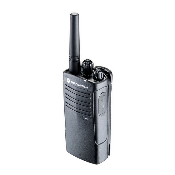
RADIO OVERVIEW PARTS OF THE RADIO Channel Antenna Selector Knob Microphone OFF/ PTT (Push-to- Volume Talk) Button SB1 - Monitor Button Indicator SB2 - Scan/ Model Label Nuisance Channel Delete Lithium-Ion Battery English... -
Page 11: On/Off/Volume Knob
ON/OFF/Volume Knob • Side Button 1 (SB1) Used to turn the radio ON or OFF and to adjust The Side Button 1 is a general button that can the radio’s volume. be configured by the Computer Programming Software - CPS. The default setting of SB1 Channel Selector Knob button is ‘Monitor’. - Page 12 This User Guide covers multiple XTNi™ Series underneath the speaker, and tells you the models, and may detail some features your following information: radio does not have. The model number of the radio is shown on the front of the radio, Frequency Transmit Power Number of...
-
Page 13: Batteries And Chargers
Motorola batteries are designed specifically to BATTERY FEATURES AND CHARGING be used with a Motorola charger and vice OPTIONS versa. Charging in non-Motorola equipment may lead to battery damage and void the About the Li-Ion Battery battery warranty. -
Page 14: Battery Recycling And Disposal
Motorola fully endorses and encourages the recycling of Li-Ion batteries. In the U.S. and Canada, Motorola participates in the nationwide Rechargeable Battery Recycling Corporation (RBRC) program for Li-Ion battery collection and recycling. -
Page 15: Installing The Lithium-Ion (Li-Ion) Battery
Turn OFF the radio. Turn OFF the radio. With the Motorola logo side up on the battery Push down the battery latch and hold it depressed pack, fit the tabs at the bottom of the battery into while removing the battery. -
Page 16: Alkaline Battery Pack (Optional Accessory)
Alkaline battery pack (optional accessory) Removing Alkaline Batteries Installing Alkaline Battery Pack Alkaline Battery Door Alkaline Battery Door Turn OFF the radio, if it is turned on. Slide the battery latches, on both sides of the Turn OFF the radio, if it is turned on. battery, downwards. -
Page 17: Power Supply, Adaptors And Drop-In Tray
Power Supply, Adaptors and Drop-in Tray Charger Adaptor Adaptor Power Supply Drop-in Tray Charger Power Supply Power Supply Your radio comes with one Drop-in Tray Charger, one Power Supply (also known as Install Remove Transformer) and a set of adaptors. Your power supply, has a ‘switchable’... -
Page 18: Installing Spring Action Belt Clip
Installing Spring Action Belt Clip Battery Life Information Li-Ion Battery Life Depending on the radio model and/or region belt clip tab the battery capacity will be different. This feature will determine the estimated battery life. When the Battery Save feature is ON spring action belt (enabled by default) the battery life will be... -
Page 19: Charging The Battery
Alkaline Battery Life The following chart provides estimations about To charge the battery (with the radio attached), the Battery Life using the Alkaline Batteries: place it in a Motorola-approved Drop-in Tray Single Unit Charger or Drop-in Tray Multi-Unit Charger. Alkaline Battery Life... -
Page 20: Charging A Stand-Alone Battery
radio facing the front of the charger, as shown. Important: Ensure that the bracket in the charger is Note: When charging a battery attached to a radio, adjusted to the correct position for turn the radio OFF to ensure a full charge. either Standard or High-capacity See ‘Operational Safety Guidelines’... -
Page 21: Identifying The Drop-In Charger's Position Before Charging Battery
Identifying the Drop-In Charger’s Position Before Charging Battery Adjustable bracket Adjustable bracket Standard High and Ultra High Capacity English... -
Page 22: Charging A High Capacity Battery
Charging a High Capacity Battery Removable Piece Removable Turn around Piece horizontal 180 degree To convert the charger from the default Repeat same procedure to return position back to charging a Standard Battery. Label on the setup to accommodate the high capacity: removable bracket should show ‘Standard Squeeze both tabs on each side of the Battery’... -
Page 23: Drop-In Tray Charger Led Indicators
Drop-in Tray Charger LED Indicators Standard Charger LED Indicator Status LED Status Comments Steady red indication for 3 Power ON The charger has powered up seconds Charging Blinking red (slow) The charger is currently charging Charging Steady red indication Battery is fully charged Complete Battery Fault(*) Blinking red (fast) -
Page 24: Estimated Charging Time
Estimated Charging Time The following table gives the estimated times to charge the battery. For further details, see ‘Accessories’ on page 58. Estimated Charging Time Battery Capacity Charging Solution Standard High Rapid Charging 1.5 hours 3 hours Solution English... -
Page 25: Charging A Radio And Battery Using A Multi
Charging a Radio and Battery Using a Multi- Insert the radio or battery into the charging pocket. Unit Charger-MUC (Optional Accessory) Notes: • This Multi-Unit Charger will also allow you to clone up to 3 radios (3 Source radios and 3 Target radios). -
Page 26: Getting Started
SELECTING A CHANNEL GETTING STARTED To select a channel, rotate the Channel For the following explanations, refer to page 8 Selector Knob and select the desired channel of the user guide. number. TURNING RADIO ON/OFF Program each channel separately. Each To turn ON the radio, rotate the ON/OFF/ channel has its own Frequency, Interference Volume Knob clockwise. -
Page 27: Receiving A Call
RECEIVING A CALL TALK RANGE XTNi radios have been designed to maximize Select a channel by rotating the Channel performance and improve transmission range Selector Knob until you reach the desired in the field. It is recommended that you do not channel. - Page 28 Channel: Current channel that the radio is For details of how to set up frequencies and using, depending upon radio model. CTCSS/DPL codes in the channels, refer to “Programming Mode” on page 31. Frequency: The frequency the radio uses to transmit/receive. Note: Interference Eliminator Codes are referred Interference Eliminator Code: These also as CTCSS/DPL codes or PL/DPL codes...
-
Page 29: Radio Led Indicators
RADIO LED INDICATORS RADIO STATUS LED INDICATION Channel Alias Edit Red heartbeat Channel Busy Solid orange Cloning Mode Two orange heartbeats Cloning In Progress Solid orange One green blink, one orange blink, one green blink, then repeat for Fatal Error at Power up 4 seconds Low Battery Orange blink... -
Page 30: Hands-Free Use/Vox
(VOX) when used with compatible VOX accessory. accessories. A short delay occurs between talking and the radio transmission. Note: To order accessories, contact your Motorola dealer. With Compatible VOX Accessories The default factory setting for VOX sensitivity level is OFF (level ‘0’). Before using VOX,... -
Page 31: Hands Free Without Accessories (Ivox)30
Hands Free without Accessories (iVOX) Default value is OFF (level 0). If you want touse the VOX feature, VOX level should be • Enable iVOX by pressing the PTT button set at a level different from 0. while turning the radio ON. •... -
Page 32: Reset To Factory Defaults
seconds while powering up the radio until you hear a quick series of beeps. To have a slightly better attack time, set Battery Save feature to OFF so that the radio is always ready to transmit or receive without any delays. Note: Battery Save feature is set to ON by default Reset To Factory Defaults Reset To Factory Defaults will set back all... -
Page 33: Programming Features
filter out static, noise, and unwanted PROGRAMMING FEATURES messages. To easily program all the features in your radio, it is recommended to use the CPS Kit which The Auto Scan feature allows you to set a includes the Programming Cable, CPS and particular channel to automatically enable scan accessories sections. - Page 34 Table 1: Programming Mode: Reading your Radio's Features Values Number Confirmation Beep LED Indication Zero beep One short orange blink One beep One short red blink Two beeps Two short red blinks Three beeps Three short red blinks Four beeps Four short red blinks Long beep One long red blink...
- Page 35 PROGRAMMING MODE Frequencies CTCSS/DPL First Second Third First Second Digit Digit Digit Digit Digit Long Long Idle Auto-Scan Enter Programming Mode Programming (PTT + SB1 + Turn ON radio) “Roll Over” Mode key chirp Long Exit Figure 1 Entering Programming Mode English...
-
Page 36: Reading Frequencies Values
Entering Programming Mode Once you are in the 'Idle' Programming Mode, you will be able to read the radio frequencies, Note: Before programming the features, make codes and auto-scan setting by short pressing sure your radio is set to the channel you the PTT button to move along the different wish to program. -
Page 37: Reading Ctcss/Dpl Values
The following is an example of the order in which your radio will be signaling the ‘118’ CTCSS/DPL code: Frequencies First Second Digit Digit First Third Reading CTCSS/DPL Values Digit Digit If you continue short pressing the PTT button, Second Digit as shown in the ”Entering Programming Mode”... -
Page 38: Reading Auto-Scan Values
Reading Auto-Scan Values Programming Frequencies, Codes and Auto-Scan After finishing reading CTCSS/DPL codes, if Each time your radio signals and beeps, you you short press PTT once again, the radio will can change the current setting value by either take you to Auto-Scan (”Entering Programming increasing it by short pressing SB1 or Mode”... -
Page 39: Programming Mode Faq
Notes: • Turn OFF the radio and enter Programming Mode again (see instructions in the beginning • If you don't want to save the value you just of this section) programmed, turn radio OFF or change channel using the channel knob. 2. -
Page 40: Programming Values Example
4. When I was programming I made a 6. I am done programming the features in mistake and program the wrong value. How this channel and want to program another can I erase it or re-program it? channel. If you make a mistake while programming a Switch to the new channel you wish to program value you have two choices: by using the Channel Selector Knob. - Page 41 • Short press the PTT button to enter • Short press the PTT button three times (Enter Frequency Mode. Radio will signal current CTCSS/DPL Programming Selection Mode). value ‘0’ (orange blink) Radio LED will blink orange to indicate that current value is ‘0’ • Press the SB1 button once •...
-
Page 42: Scan
Example of Programming Auto Scan OTHER PROGRAMMING FEATURES Auto-Scan is the last Programming Mode and SCAN can be set to "ON" or "OFF" on a particular Scan allows you to monitor other channels in channel. To set Auto Scan to “ON”: order to detect conversations. -
Page 43: Editing Scan List
(refer to ”CPS (Computer Programming scanning, the radio will transmit on the channel Software)” on page 42. which was selected before Scan was activated. Nuisance Channel Delete If no transmission occurs within five seconds, Nuisance Channel Delete allows you to scanning will resume. -
Page 44: Cps (Computer Programming Software)
Programming Cable(*). CPS Software is Authorized Motorola Dealer. Contact your available for free as web based downloadable English Motorola Point of Purchase for details software at www.motorola.com/XTNi. Note: (*) CPS Programming Cable is an To do so, connect the XTNi radio via the Drop- accessory sold separately. -
Page 45: Bandwidth Select
Bandwidth Select Scramble Default setting for Bandwidth Select is 12.5 The Scramble feature makes transmissions KHz. Some frequencies have selectable sound garbled to anyone listening without the channel spacing, which must match other same code. Scramble default value is OFF. radios for optimum audio quality. -
Page 46: Cloning Radios
CLONING RADIOS by pairs as follows: 1 and 2 or 3 and 4 or 5 and You can copy XTNi™ Series radio profiles from one Source radio to a Target radio by using any of these 3 methods: One Multi Unit Charger (optional accessory) Two single unit chargers and a Radio-to- Radio cloning cable (optional accessory) -
Page 47: When Ordering The Muc
MUC. When ordering the MUC See ”Chargers” on page 59 for the MUC part number. Note: (*) MUC pockets numbers should be readfrom left to right with the Motorola logo facing front. English... - Page 48 Operating Instructions • Long press the PTT button and SB2 simaltaneously while turning the radio ON. 1. Before beginning the cloning process, • Wait for 3 seconds before releasing the make sure you have: buttons until a distinctive audible tone is heard. •...
-
Page 49: What To Do If Cloning Fails
What to do if cloning fails Attention: This cloning cable is designed to operate only with compatible Motorola The radio will emit an audible ‘bonk’ indicating RLN6170 (Rapid) Single Unit Charger. that the cloning process has failed. In the event... -
Page 50: Troubleshooting
TROUBLESHOOTING Symptom Try This Recharge or replace the Li-Ion battery. Replace AA batteries. No Power Extreme operating temperatures affect battery life. Refer to ‘"About the Li- Ion Battery" on page 11’. Confirm Interference Eliminator Code is set. Frequency or Interference Hearing other noises or Eliminator Code may be in use. - Page 51 Symptom Try This Make sure the PTT button is completely pressed if you're transmitting. Confirm radios have the same Channel, Frequency, Interference Eliminator Code and Scramble Code settings. Refer to the ‘Talking and Monitoring’ Section on page 24 for further information. Recharge, replace and/or reposition batteries.
- Page 52 Symptom Try This Check radio/battery is properly inserted and check battery/charger contacts to be sure they are clean and charging pin is inserted correctly. Drop-in Charger LED Refer to ‘Charging the Battery’ section on page 17, ‘Drop-in Tray Charger light does not come on LED Indicators’...
-
Page 53: Use And Care
USE AND CARE Use a soft damp cloth Do not immerse Do not use alcohol or to clean the exterior in water cleaning solutions If the radio is submerged in water... Turn radio OFF and Dry with soft cloth Do not use radio until remove batteries completely dry English... -
Page 54: Frequency And Code Charts
Motorola XTNi Series two-way FREQUENCY AND CODE radios with other business radios. Most of the CHARTS frequency position are the same as Spirit M, GT, S, XTN Series Frequencies. The charts in this section provide Frequency and Code information. These charts are useful... - Page 55 CTCSS CTCSS CTCSS CTCSS 67.0 107.2 167.9 71.9 110.9 173.8 74.4 114.8 179.9 77.0 118.8 186.2 79.7 192.8 82.5 127.3 203.5 85.4 131.8 210.7 88.5 136.5 218.1 91.5 141.3 225.7 94.8 146.2 233.6 97.4 151.4 241.8 100.0 156.7 250.3 103.5 162.2 122 (*) 69.3...
- Page 56 DPL Codes (cont.) Code Code Code English English...
- Page 57 DPL Codes (cont.) Code Code Code English...
- Page 58 Do • Defects of damage from improper testing, not return your radio to Motorola. To be eligible operation, maintenance, adjustment, or any to receive warranty service, you must present alteration or modification of any kind.
- Page 59 • Defects or damage due to range. • Products rented on a temporary basis. • Defects or damage due to moisture, liquid or spills. • Periodic maintenance and repair or replacement of parts due to normal usage, wear and tear. •...
-
Page 60: Accessories
CARRY ACCESSORIES ACCESSORIES Part No. Description AUDIO ACCESSORIES RLN6302 Hard Leather Carry Case Part No. Description RLN6307 Spring Action Belt Clip 00115 Remote Speaker Mic BR SOFTWARE APPLICATIONS 00168 Lightweight headset Part No. Description 00117 Headset w/Swivel Boom Mic IXEN4007 Computer Programming Software 00118 Earbud w/Clip PTT Mic BR... -
Page 61: Chargers
Note: (*) Attention: Certain accessories may be or may Part No. Description not be available at the time of purchase. Please contact your Motorola point of purchase or visit IXPN4019 Rapid Charging Kit - European www.motorola.com/XTNi or www.motorola.com/ (**) radios/business for latest information on accessories. - Page 63 MOTOROLA, the Stylized M Logo,XTNi Series and all other trademarks indicated as such herein are trademarks of Motorola, Inc. ® Reg. U.S. Pat. & Tm. Off. All other product or service names are the property of their respective owners. © 2007 Motorola, Inc.