Motorola EMS APX 6000 User Manual
Hide thumbs
Also See for EMS APX 6000:
- User manual (200 pages) ,
- Manual (105 pages) ,
- Service manual (438 pages)
Table of Contents
Advertisement
Quick Links
Advertisement
Table of Contents

Related Manuals for Motorola EMS APX 6000


Summary of Contents for Motorola EMS APX 6000
- Page 1 EMS APX 6000 11/2/15...
-
Page 2: Table Of Contents
Feature Page Zone/Modes-‐Names a nd L ocation 3,4,5 Battery/Charger Antenna Connector/Holder Turn O n Volume Parts a nd C ontrols Menu a nd N avigation PTT a nd I cons 113,14,15,16,17,18 LED ... - Page 3 VB F IRE/EMS HOSP/LG VB P OLICE 1 VB P OLICE 2 EM M GMT CHESAPEAKE NORFOLK CURRITUCK FIRE/EMS HOSP/LG POLICE 1 POLICE 2 DIG E M CHES NORFOLK CURR 1 E MS C OMMAND 1 V A B EACH G EN 1 ...
- Page 4 PD M UTUAL A ID VB S HERIFF DIG S CHOOLS SCHOOLS PUBLIC W KS PUBLIC U TL MISC/GEN MISC/SERV M/AID SHERIFF SCHOOLS SCHOOLS PUB W RKS PUB U TL MIS/GEN MIS S ER 1 ...
- Page 5 This page intentionally blank and reserved for additional information in the future. 11/2/15...
-
Page 6: Battery/Charger
“hazardous atmosphere”. • DO NOT discard batteries in a fire. The Motorola-approved battery shipped with your radio is uncharged. Prior to using a new battery, charge it for a minimum of 16 hours to ensure optimum capacity and performance. -
Page 7: Attaching The Antenna
Attaching the Antenna To remove the battery, turn the radio off. Squeeze With the radio turned off, set the antenna in its receptacle and the release latches at the turn clockwise to attach it to the radio. bottom of the battery until the battery releases from the radio. - Page 8 Attaching the Accessory Connector Using the Carry Holder Cover Position the radio within The accessory connector is located on the antenna side of the the carry holder with the radio. It is used to connect accessories to the radio. main speaker facing outward.
-
Page 9: Turning On The Radio
Turning On the Radio To remove the radio from Rotate the On/Off/Volume Control Knob clockwise until you the carry holder, place the hear a click. tip of your fingers on the ledge of the carry holder and push at the bottom of the radio until the radio is released from it. -
Page 10: Adjusting The Volume
Note: If the power-up test is successful, but you see Adjusting the Volume Hardware board absent or Hw Board Mismatch. Send your radio to the qualified technician to fix this To increase the volume, turn the On/Off/Volume Control Knob error. clockwise. -
Page 11: Antenna
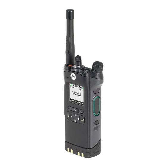
Radio Parts and Controls Antenna On/Off/Volume 16-Position Control Knob Select Knob* 3-Position A/B/C Microphone Display Switch* Top (Orange) 2-Position Concentric Button* Switch* Main Display Microphone Menu Select Top Side (Select) Accessory Buttons Button* Connector Main Speaker Push-to-Talk (PTT) Button Data Feature Bluetooth Button Pairing... -
Page 12: Accessing The Preprogrammed Functions
Accessing the Preprogrammed Functions Using the Navigation Buttons Home Button You can access various radio functions through one of the following ways: button returns you to the Home (default) screen. In most • A short or long press of the relevant programmable buttons. cases, this is the current mode. -
Page 13: Identifying Status Indicators
Push-To-Talk (PTT) Button Identifying Status Indicators The PTT button on the side Your radio indicates its operational status through the following: of your radio serves two basic purposes : Status Icons ....... . Text Messaging Service (TMS) Icons. - Page 14 The following icons are for the front display screen unless Received Signal Strength Indicator (RSSI) indicated otherwise. The number of bars displayed represents the received signal strength for the current site, for Receiving Top Display trunking only. The more stripes in the icon, the Radio is receiving a call or data.
- Page 15 In-Call User Alert Priority Channel Scan • • On = The feature is enabled. Voice muting of Blinking dot = Radio detects activity on the affiliated trunking talkgroup or channel designated as Top Display selected conventional channel is Priority-One. activated. •...
- Page 16 Basic Zone Bank 2 AES Secure Operation Top Display • • D = Radio is in Zone 4. On = AES Secure operation. • • E = Radio is in Zone 5. Off = Clear operation. • • F = Radio is in Zone 6. Blinking = Receiving an encrypted voice call.
- Page 17 Data Activity Data activity is present. Bluetooth On Bluetooth is on and ready for bluetooth connection. Top Display Bluetooth Connected Bluetooth is currently connected to the external bluetooth device. Top Display 11/2/15 English...
- Page 18 Call Type Icons The following icons appear on your radio’s main display, when Landline phone number. you make or receive a call, or view selected call lists, to indicate the different call types associated with an alias or ID. Landline phone number added to a Call List. Radio number.
-
Page 19: Led Indicator
LED Indicator Solid red – Radio is transmitting. The LED indicator shows the operational status of your radio. Blinking red – Radio is transmitting at low battery condition. Rapidly blinking red – Radio has failed the self test upon powering up or encountered a fatal error. Solid yellow (Conventional Only) –... -
Page 20: Intelligent L Ighting
Intelligent Lighting Indicators This feature temporary changes the backlight of the top display screen, and adds a color bar to the main display screen to help signal that a radio event has occurred. Note: This feature must be preprogrammed by a qualified radio technician. Backlight and Bar Color Notification When... -
Page 21: Alert Tones
Alert Tones Your radio uses alert tones to inform you of your radio’s condition. The following table lists these tones and when they occur. You Hear Tone Name Heard Radio Self Test Fail When radio fails its power-up self test. Reject When an unauthorized request is made. - Page 22 You Hear Tone Name Heard Valid Key-Press When avcorrect key is pressed. Radio Self Test Pass When radio passes its power-up self test. Clear Voice At beginning of a non-coded communication. Short, Priority Channel Medium-Pitched When activity on a priority channel is received. Received Tone Emergency Alarm /Call...
- Page 23 You Hear Tone Name Heard Short, High-Pitched Low-Battery Chirp When battery is below preset threshold value. Tone (Chirp) Fast Ringing When system is searching for target of Private Call. Ringing Enhanced Call Sent When waiting for target of Private Call to answer the call. Phone Call Received When a land-to-mobile phone call is received.
- Page 24 You Hear Tone Name Heard Man Down Continuous When radio is in Man Down mode and prepares to transmit Emergency Alarm A Group of Very Tone when the timer of this alarm ends. High-Pitched Critical Man Down When radio is in Man Down Enhanced mode and prepares to transmit Tones Continuous Tone Emergency Alarm when the timer of this alarm ends.
-
Page 25: Selecting A Zone
Selecting a Zone A zone is a group of channels. Follow the procedure below. < > to Zone. Press the Menu Select button directly below Zone. 3-Position A/B/C Switch to the required zone. Press the Menu Select button directly below Sel to confirm the displayed zone. -
Page 26: Select A C Hannel
Selecting a Radio Channel Procedure: Turn the preprogrammed 16-Position Select Knob to the A channel is a group of radio characteristics, such as transmit/ desired channel. receive frequency pairs. Follow the procedure below. < > to Chan. Press the Menu Select button directly below Chan. to the required channel. -
Page 27: Receiving And Responding To A Radio Call
Receiving and Responding to a Radio Call Once you have selected the required channel and/or zone, you Receiving and Responding to a Talkgroup Call can proceed to receive and respond to calls. To receive a call from a group of users, your radio must be configured as part of that talkgroup. -
Page 28: Making A Radio Call
Making a Radio Call ASTRO Conventional Only: The LED lights up solid red. The display shows the talkgroup alias or ID. You can select a zone, channel, subscriber ID, or talkgroup by using: Trunking Only: • The LED lights up solid red. The preprogrammed Zone switch •... -
Page 29: Repeater Or Direct Operation
Repeater or Direct Operation Conventional Mode Operation ® The REPEATER operation increases the radio’s range by Your radio may be preprogrammed to receive Private-Line connecting with other radios through a repeater. The transmit (PL) calls. and receive frequencies are different. Procedure: The DIRECT or “talkaround operation”... -
Page 30: Monitoring Features
Monitoring Features Radio users who switch from analog to digital radios often Release the PTT button to receive (listen). assume that the lack of static on a digital channel is an indication that the radio is not working properly. This is not the case. -
Page 31: Scan Lists
Scan Lists Editing the Scan List This feature lets you change scan list members and priorities. Scan lists are created and assigned to individual channels/ Procedure: groups. Your radio scans for voice activity by cycling through the Long press the preprogrammed Scan List Programming channel/group sequence specified in the scan list for the current button (side button) and proceed to Step 3. - Page 32 Use the 16-Position Select knob to select additional Press the Select button one or more times to change the channels to be added or deleted. scan list status icon of the currently displayed channel. Move the Scan List Programming switch out of to select more list members whose scan status you programming position.
- Page 33 Scan Viewing and Changing the Priority Status Procedure: This feature allows you to monitor traffic on different channels Below the Sel, Del, and Rcl screen, press the Menu Select by scanning a preprogrammed list of channels. button directly below Sel to view and/or change the priority status of the currently displayed channel.
- Page 34 Making a Dynamic Priority Change (Conventional Deleting a Nuisance Channel Scan Only) If a channel continually generates unwanted calls or noise (termed a “nuisance” channel), you can temporarily remove the While the radio is scanning, the dynamic priority change feature unwanted channel from the scan list.
-
Page 35: Emergency Operation
Emergency Operation Note: The radio operates in the normal dispatch manner The Emergency feature is used to indicate a critical situation. while in Emergency Call, except if enabled, it returns to one of the following: If the Top (Orange) button is preprogrammed to send an emergency signal, this signal overrides any other •... - Page 36 Sending an Emergency Alarm This feature allows you to send a data transmission, which Sending an Emergency Call (Trunking Only) identifies the radio sending the emergency, to the dispatcher. This feature gives your radio priority access on a channel. Note: Emergency button press timer by default is set to 1 Procedure:...
- Page 37 Sending an Emergency Alarm with Emergency Press and hold the PTT button. Speak clearly into the Call microphone. This feature gives your radio priority access on a channel for Release the PTT button to end the transmission and wait for conventional system, and to a talkgroup for trunking system.
- Page 38 Changing Channels during Emergncy For ALL Emergency signals, when changing channels: • If the new channel is also preprogrammed for Emergency, you can change channels while in Emergency operation. The emergency alarm or call continues on the new channel. •...
- Page 39 • The Global Positioning System (GPS) Inside of buildings, trains, or other covered vehicles • Under any other metal or concrete roof or structure This feature uses information from the Global Positioning • Between tall buildings or under dense tree-cover System (GPS) satellites orbiting the Earth to determine the approximate geographical location of your radio, expressed as •...
- Page 40 The radio also stores four (4) preprogrammed waypoints. These Enhancing GPS Performance coordinates cannot be deleted. Sometimes, the GPS feature may be unable to complete a location calculation successfully. You then see a message Programmable Waypoints Preprogrammed Waypoints indicating that your radio cannot connect to enough visible Fixed location coordinates: satellites.
- Page 41 Press the Menu Select button directly below Rfsh to obtain Accessing the Outdoor Location Feature a new location fix. Note: An ON menu key may be present on the location menu The top line temporarily displays Please wait while the new if it is preprogrammed by the dealer or system location is being determined.
- Page 42 Saving a Waypoint Viewing a Saved Waypoint Procedure: Procedure: While in the current location display: While in the current location display: Press the Menu Select button directly below Optn. Press the Menu Select button directly below Optn. to Save as Waypt and press the Menu Select to Waypoints and press the Menu Select button button directly below Sel.
- Page 43 Deleting a Single Saved Waypoint Deleting All Saved Waypoints Procedure: Procedure: While in the current location display: While in the current location display: Press the Menu Select button directly below Optn. Press the Menu Select button directly below Optn. to Waypoints and press the Menu Select button to Waypoints and press the Menu Select button directly below Sel.
- Page 44 Measuring the Distance and Bearing from a Saved Using the Location Feature While in Emergency Waypoint Mode Procedure: When the Emergency feature is activated by pressing the While in the current location display: emergency button, the radio exits the Location menu and returns to the Home (default) screen so that you can see which Press the Menu Select button directly below Optn.
- Page 45 Going Out of Range When your radio goes out of the range of the system, it can no longer lock onto a control channel. Using the Failsoft System Procedure: The failsoft system ensures continuous radio communications during a trunked system failure. If a trunking system fails You hear a low-pitched tone.
- Page 46 Selecting a Radio Profile- APX7000/6000 only-no profiles on XE This feature allows you to manually switch the visual and audio settings of the radio. The display, backlight, alert tones, and audio settings are defined according to the preprogrammed radio settings of each radio profile. to scroll through the menu selections.
-
Page 47: Controlling The Display Backlight
Controlling the Display Backlight Using the Time-Out Timer You can enable or disable the radio’s display backlight as This feature turns off your radio’s transmitter. You cannot needed, if poor light conditions make the display difficult to read. transmit longer than the preset timer setting. - Page 48 IMPRES™ Battery Annunciator Use the Options Menu. This feature displays the current capacity and charges cycles of < > to Batt. your battery when a IMPRES Battery is powering your radio. This feature must be enabled in your radio to see the Press the Menu Select button directly below Batt.
- Page 49 Procedure: Accessing the Radio Information Press the preprogrammed Info button and proceed to Step 3. This feature displays the following information of your radio: Follow the procedure below. • • Host Version DSP Version < > to Info. • •...
- Page 50 Caring for Your Radio Helpful Tips • Take a moment to review the following: The APX 6000/ radio casting has Caring for Your Radio ......a vent port that Cleaning Your Radio .
- Page 51 Apply the solution sparingly with a stiff, non-metallic, short- assure the watertight integrity of the radio. Motorola details the disassembly, test, and bristled brush, making sure excess detergent does not get reassembly procedures along with necessary entrapped near the connectors, controls or crevices.
- Page 52 Proper repair and maintenance procedures will assure efficient Do not pound, drop, or throw the radio unnecessarily. Never operation and long life for this product. A Motorola maintenance carry the radio by the antenna. agreement will provide expert service to keep this and all other •...
-
Page 53: Taking Care Of The Battery
Taking Care of the Battery Gauge Battery Charge Checking the Battery Charge Status 76% to 100% full* Your radio can indicate the battery’s charge status through: Top Display • the LED and sounds. • the fuel gauge icon on the display. You can also check the battery charge status via the menu entry. - Page 54 Battery Recycling and Disposal Gauge Battery Charge In the U.S. and Canada, Motorola participates in the nationwide Rechargeable Battery Recycling Corporation (RBRC) program for battery collection and recycling. Many retailers and dealers 11% to 25%* Top Display participate in this program.