
Related Manuals for Nokia MOBILE TERMINAL


Summary of Contents for Nokia MOBILE TERMINAL
- Page 1 Nokia Customer Care Service Manual RM-356 (Nokia 5800 XpressMusic; L3&4) Mobile Terminal Part No: (Issue 1) COMPANY CONFIDENTIAL Copyright © 2008 Nokia. All rights reserved.
- Page 2 RM-356 Amendment Record Sheet Amendment Record Sheet Amendment No Date Inserted By Comments Issue 1 10/2008 Page ii COMPANY CONFIDENTIAL Issue 1 Copyright © 2008 Nokia. All rights reserved.
- Page 3 Nokia operates a policy of continuous development. Nokia reserves the right to make changes and improvements to any of the products described in this document without prior notice. Under no circumstances shall Nokia be responsible for any loss of data or income or any special, incidental, consequential or indirect damages howsoever caused.
-
Page 4: Warnings And Cautions
WCDMA networks and cause problems to 3G cellular phone communication in a wide area. • During testing never activate the GSM or WCDMA transmitter without a proper antenna load, otherwise GSM or WCDMA PA may be damaged. Page iv COMPANY CONFIDENTIAL Issue 1 Copyright © 2008 Nokia. All rights reserved. - Page 5 Use only approved accessories and batteries. Do not connect incompatible products. CONNECTING TO OTHER DEVICES When connecting to any other device, read its user’s guide for detailed safety instructions. Do not connect incompatible products. Issue 1 COMPANY CONFIDENTIAL Page v Copyright © 2008 Nokia. All rights reserved.
- Page 6 RM-356 ESD protection ESD protection Nokia requires that service points have sufficient ESD protection (against static electricity) when servicing the phone. Any product of which the covers are removed must be handled with ESD protection. The SIM card can be replaced without ESD protection if the product is otherwise ready for use.
- Page 7 All of the above suggestions apply equally to the product, battery, charger or any accessory. Issue 1 COMPANY CONFIDENTIAL Page vii Copyright © 2008 Nokia. All rights reserved.
- Page 8 Our policy is of continuous development; details of all technical modifications will be included with service bulletins. While every endeavour has been made to ensure the accuracy of this document, some errors may exist. If any errors are found by the reader, NOKIA MOBILE PHONES Business Group should be notified in writing/e- mail. Please state: •...
-
Page 9: Battery Information
Batteries' performance is particularly limited in temperatures well below freezing. Do not dispose of batteries in a fire! Dispose of batteries according to local regulations (e.g. recycling). Do not dispose as household waste. Issue 1 COMPANY CONFIDENTIAL Page ix Copyright © 2008 Nokia. All rights reserved. - Page 10 RM-356 Battery information (This page left intentionally blank.) Page x COMPANY CONFIDENTIAL Issue 1 Copyright © 2008 Nokia. All rights reserved.
- Page 11 RM-356 Nokia 5800 XpressMusic; L3&4 Service Manual Structure Nokia 5800 XpressMusic; L3&4 Service Manual Structure 1 General Information 2 Service Tools and Service Concepts 3 BB Troubleshooting and Manual Tuning Guide 4 RF troubleshooting 5 Camera Module Troubleshooting 6 System Module and User Interface...
- Page 12 RM-356 Nokia 5800 XpressMusic; L3&4 Service Manual Structure (This page left intentionally blank.) Page xii COMPANY CONFIDENTIAL Issue 1 Copyright © 2008 Nokia. All rights reserved.
- Page 13 Nokia Customer Care 1 — General Information Issue 1 COMPANY CONFIDENTIAL Page 1 –1 Copyright © 2008 Nokia. All rights reserved.
- Page 14 RM-356 General Information (This page left intentionally blank.) Page 1 –2 COMPANY CONFIDENTIAL Issue 1 Copyright © 2008 Nokia. All rights reserved.
-
Page 15: Table Of Contents
Table 4 Messaging ............................... 1–10 Table 5 Music ............................... 1–10 Table 6 Navigation .............................. 1–11 Table 7 Power ..............................1–11 List of Figures Figure 1 View of RM-356............................1–5 Issue 1 COMPANY CONFIDENTIAL Page 1 –3 Copyright © 2008 Nokia. All rights reserved. - Page 16 RM-356 General Information (This page left intentionally blank.) Page 1 –4 COMPANY CONFIDENTIAL Issue 1 Copyright © 2008 Nokia. All rights reserved.
-
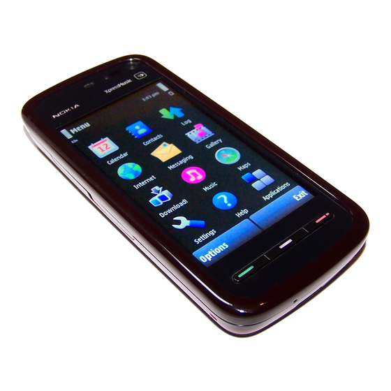
Page 17: Product Selection
RM-356 also supports MIDP Java 2.0, providing a good platform for compelling 3rd party applications. Figure 1 View of RM-356 Product features and sales package New hardware characteristics • Touch screen phone: Issue 1 COMPANY CONFIDENTIAL Page 1 –5 Copyright © 2008 Nokia. All rights reserved. - Page 18 • Stereo music player supporting MP3, SpMidi, AAC, AAC+, eAAC+, WMA • 3D stereo ringing tones, 64 polyphonic Midi, MP3 tones, video ringing tones • Stereo FM Radio Productivity Context management • Full OMA client provisioning Page 1 –6 COMPANY CONFIDENTIAL Issue 1 Copyright © 2008 Nokia. All rights reserved.
-
Page 19: Product And Module List
General Information • PIM (Calendar + Contacts) • OTA provisioning & over the air SW update (FOTA) • Nokia PC Suite connectivity with USB, Bluetooth • Web Browser (OSS), Java ™ MIDP 2.0, XHTML browsing over TCP/IP Messaging • MS, MMS (OMA 1.3) •... -
Page 20: Mobile Enhancements
Table 1 Audio Enhancement Type Audio controller AD-54 Hearing aid HDA-12 Wired headsets HS-16 HS-41 HS-43 HS-45 (+ AD-54) HS-45 HS-48 WH-201 WH-202 WH-500 WH-600 WH-700 WH-800 Page 1 –8 COMPANY CONFIDENTIAL Issue 1 Copyright © 2008 Nokia. All rights reserved. -
Page 21: Table 2 Car
HS-79W HS-89W HS-91W HS-94W HS-95W HS-96W HS-100W Table 2 Car Enhancement Type FM transmitter CA-300 Mobile holder CR-39 CR-82 CR-99 CR-103 Mobile holder mounting device HH-12 Issue 1 COMPANY CONFIDENTIAL Page 1 –9 Copyright © 2008 Nokia. All rights reserved. -
Page 22: Table 3 Data
Wireless keyboard SU-8W Digital pen SU-27W CP-306 plectrum stylus CP-306 Table 5 Music Enhancement Type Wireless Audio Gateway AD-42W Wireless speakers MD-5W MD-7W Music speakers MD-6 MD-8 Page 1 –10 COMPANY CONFIDENTIAL Issue 1 Copyright © 2008 Nokia. All rights reserved. -
Page 23: Technical Specifications
Main RF characteristics for GSM850/900/1800/1900 and WCDMA VIII (900) and WCDMA I (2100) phones Parameter Unit Cellular system GSM850, EGSM900, GSM1800/1900, WCDMA VIII (900) and WCDMA I (2100) Issue 1 COMPANY CONFIDENTIAL Page 1 –11 Copyright © 2008 Nokia. All rights reserved. - Page 24 EDGE1900:+0 … +26dBm/1.0mW … 400mW Number of RF channels GSM850: 124 GSM900: 174 GSM1800: 374 GSM1900: 299 WCDMA VIII (900): 152 WCDMA I (2100): 277 Channel spacing 200 kHz Page 1 –12 COMPANY CONFIDENTIAL Issue 1 Copyright © 2008 Nokia. All rights reserved.
-
Page 25: Battery Endurance
Music playback BL-5J 1320 Up to 8.8 h (GSM) Up to 406.2 h (GSM) Up to 35h Up to 5 h (WCDMA) Up to 400 h (GSM) Issue 1 COMPANY CONFIDENTIAL Page 1 –13 Copyright © 2008 Nokia. All rights reserved. - Page 26 RM-356 General Information (This page left intentionally blank.) Page 1 –14 COMPANY CONFIDENTIAL Issue 1 Copyright © 2008 Nokia. All rights reserved.
- Page 27 Nokia Customer Care 2 — Service Tools and Service Concepts Issue 1 COMPANY CONFIDENTIAL Page 2 –1 Copyright © 2008 Nokia. All rights reserved.
- Page 28 RM-356 Service Tools and Service Concepts (This page left intentionally blank.) Page 2 –2 COMPANY CONFIDENTIAL Issue 1 Copyright © 2008 Nokia. All rights reserved.
-
Page 29: Table Of Contents
SS-62 ................................2–15 SS-93 ................................2–16 SX-4................................2–16 Cables................................2–16 CA-101 ................................ 2–16 CA-31D ................................ 2–16 CA-35S................................. 2–17 CA-58RS............................... 2–17 CA-75U ................................ 2–17 CA-89DS ..............................2–18 Issue 1 COMPANY CONFIDENTIAL Page 2 –3 Copyright © 2008 Nokia. All rights reserved. - Page 30 Figure 9 RF testing concept with RF coupler ....................2–28 Figure 10 Service concept for RF testing and RF/BB tuning ................2–29 Figure 11 WLAN functionality testing concept with SB-7 ................2–30 Page 2 –4 COMPANY CONFIDENTIAL Issue 1 Copyright © 2008 Nokia. All rights reserved.
-
Page 31: Service Tools
RJ-230 is a soldering jig used for soldering and as a rework jig for the engine module. SA-131 RF coupler SA-131 is a RF coupler for GPS testing. It is used together with SS-62. Issue 1 COMPANY CONFIDENTIAL Page 2 –5 Copyright © 2008 Nokia. All rights reserved. -
Page 32: Sa-166
The following table shows attenuations from the antenna pads of the mobile terminal to the SMA connectors of SA-166 . The setup used for measuring the values is SA-166 + FS-77 + CU-4. •... -
Page 33: Rework Jigs And Stencils
(Z7541). It is used together with the ST-55 stencil. RJ-166 Rework jig RJ-166 is a jig used when servicing the accelerometer (N6501). It is used together with the ST-53 stencil. Issue 1 COMPANY CONFIDENTIAL Page 2 –7 Copyright © 2008 Nokia. All rights reserved. -
Page 34: Rj-169
This rework jig takes the FEM or power amplifier (PA) module (N7520) for spreading the soldering paste to the component. Must be used together with the ST-40 stencil. Page 2 –8 COMPANY CONFIDENTIAL Issue 1 Copyright © 2008 Nokia. All rights reserved. -
Page 35: St-29
It is used together with the rework jigs RJ-157 and RJ-160. ST-59 Rework stencil ST-59 is a rework stencil used when servicing the WCDMA PA (N7540) component. It is used together with rework jig RJ-169. Issue 1 COMPANY CONFIDENTIAL Page 2 –9 Copyright © 2008 Nokia. All rights reserved. -
Page 36: General Tools
Universal power supply for FPS-21; included in the FPS-21 sales package. Input 100V…230V 50Hz…60Hz, output voltage of 12 V and output current up to 3 A. Page 2 –10 COMPANY CONFIDENTIAL Issue 1 Copyright © 2008 Nokia. All rights reserved. - Page 37 4 Connect an FBUS cable (if necessary). 5 Start Phoenix service software. Note: Phoenix enables CU-4 regulators via USB when it is started. Reconnecting the power supply requires a Phoenix restart. Issue 1 COMPANY CONFIDENTIAL Page 2 –11 Copyright © 2008 Nokia. All rights reserved.
- Page 38 FPS-10 sales package includes: • FPS-10 prommer • Power Supply with 5 country specific cords • USB cable Note: FPS-21 is substitute FPS-10 if FPS-10 has not been set Page 2 –12 COMPANY CONFIDENTIAL Issue 1 Copyright © 2008 Nokia. All rights reserved.
-
Page 39: Fps-21
WCDMA network, a shield box is needed in all testing, tuning and fault finding which requires WCDMA RF signal. The shield box is not an active device, it contains only passive filtering components for RF attenuation. Issue 1 COMPANY CONFIDENTIAL Page 2 –13 Copyright © 2008 Nokia. All rights reserved. - Page 40 • SB-6 test box • Installation and warranty information SPS-1 Soldering Paste Spreader The SPS-1 allows spreading of solder to the LGA components pads over the rework stencils. Page 2 –14 COMPANY CONFIDENTIAL Issue 1 Copyright © 2008 Nokia. All rights reserved.
- Page 41 • provides standardised interface towards Control Unit • provides RF connection using galvanic connector or coupler • multiplexing between USB and FBUS media, controlled by VUSB Issue 1 COMPANY CONFIDENTIAL Page 2 –15 Copyright © 2008 Nokia. All rights reserved.
-
Page 42: Cables
USB cable The CA-31D USB cable is used to connect FPS-10 or FPS-11 to a PC. It is included in the FPS-10 and FPS-11 sales packages. Page 2 –16 COMPANY CONFIDENTIAL Issue 1 Copyright © 2008 Nokia. All rights reserved. -
Page 43: Ca-35S
It can also be used while video conferencing. The cable is used to connect the 3.5 mm AV connector of the phone to the RCA connectors of an AV device. Issue 1 COMPANY CONFIDENTIAL Page 2 –17 Copyright © 2008 Nokia. All rights reserved. -
Page 44: Ca-89Ds
PCS-1 Power cable The PCS-1 power cable (DC) is used with a docking station, a module jig or a control unit to supply a controlled voltage. Page 2 –18 COMPANY CONFIDENTIAL Issue 1 Copyright © 2008 Nokia. All rights reserved. -
Page 45: Issue
RF measurement equipment. SMA to N-Connector approximately 610 mm. Attenuation for: • GSM850/900: 0.3+-0.1 dB • GSM1800/1900: 0.5+-0.1 dB • WCDMA900: 0.3+-0.1 dB • WCDMA2100: 0.6+-0.1dB Issue 1 COMPANY CONFIDENTIAL Page 2 –19 Copyright © 2008 Nokia. All rights reserved. -
Page 46: Service Concepts
POS (Point of Sale) flash concept Type Description Product specific tools BL-5J Battery Other tools FLS-5 POS flash dongle PC with Phoenix service software Cables CA-101 Micro USB cable Page 2 –20 COMPANY CONFIDENTIAL Issue 1 Copyright © 2008 Nokia. All rights reserved. -
Page 47: Flash Concept With Fps-10
Other devices FPS-10 Flash prommer box PKD-1/PK-1 SW security device SS-46 Interface adapter PC with Phoenix service software Cables XCS-4 Modular cable CA-35S Power cable USB cable Issue 1 COMPANY CONFIDENTIAL Page 2 –21 Copyright © 2008 Nokia. All rights reserved. -
Page 48: Flash Concept With Fps-21
Other devices FPS-21 Flash prommer box AC-35 Power supply PK-1/PKD-1 SW security device SS-46 Interface adapter PC with Phoenix service software Cables CA-89DS Service cable USB cable Page 2 –22 COMPANY CONFIDENTIAL Issue 1 Copyright © 2008 Nokia. All rights reserved. -
Page 49: Flash Concept With Fps-10
SW security device SS-62 Flash adapter base SX-4 Smart card PC with Phoenix service software Cables PCS-1 Power cable XCS-4 Modular cable Standard USB cable USB cable Issue 1 COMPANY CONFIDENTIAL Page 2 –23 Copyright © 2008 Nokia. All rights reserved. -
Page 50: Flash Concept With Fps-21
Flash adapter base SX-4 Smart card (for DCT-4 generation mobile device programming) PC with Phoenix service software Cables PCS-1 Power cable CA-89DS Service cable Standard USB cable Page 2 –24 COMPANY CONFIDENTIAL Issue 1 Copyright © 2008 Nokia. All rights reserved. -
Page 51: Module Jig Service Concept
Smart card PC with Phoenix service software Measurement equipment Cables CA-58RS RF service cable (product-specific adapter cable) PCS-1 DC power cable XCS-4 Modular cable XRS-6 RF cable Issue 1 COMPANY CONFIDENTIAL Page 2 –25 Copyright © 2008 Nokia. All rights reserved. -
Page 52: Rf Testing Concept With Rf Coupler
CU-4 Control unit SX-4 Smart card FPS-10 Flash prommer box PKD-1/PK-1 SW security device SS-62 Flash adapter base Measurement equipment PC with Phoenix service software Cables Page 2 –26 COMPANY CONFIDENTIAL Issue 1 Copyright © 2008 Nokia. All rights reserved. -
Page 53: Service Concept For Rf Testing And Rf/Bb Tuning
Figure 8 Service concept for RF testing and RF/BB tuning Type Description Product specific devices MJ-165 Module jig Other devices CU-4 Control unit PK-1/PKD-1 SW security device SX-4 Smart card Measurement equipment Smart card reader Issue 1 COMPANY CONFIDENTIAL Page 2 –27 Copyright © 2008 Nokia. All rights reserved. -
Page 54: Gps Testing Concept With Gps Rf Coupler
Figure 9 RF testing concept with RF coupler Type Description Product specific devices FS-77 Flash adapter SA-131 GPS RF coupler Other devices CU-4 Control unit SX-4 Smart card JXS-1 RF shield box Page 2 –28 COMPANY CONFIDENTIAL Issue 1 Copyright © 2008 Nokia. All rights reserved. -
Page 55: Bluetooth Testing Concept With
Interface cable USB cable Bluetooth testing concept with SB-6 Figure 10 Service concept for RF testing and RF/BB tuning Type Description Product specific devices FS-77 Flash adapter Issue 1 COMPANY CONFIDENTIAL Page 2 –29 Copyright © 2008 Nokia. All rights reserved. -
Page 56: Wlan Functionality Testing Concept With
WLAN functionality testing concept with SB-7 Figure 11 WLAN functionality testing concept with SB-7 Type Description Product specific tools FS-77 Flash adapter Other tools CU-4 Control unit Page 2 –30 COMPANY CONFIDENTIAL Issue 1 Copyright © 2008 Nokia. All rights reserved. -
Page 57: Table 7 Power
Service Tools and Service Concepts Type Description PCS-1 DC power cable PK-1 SW Security device SS-62 Generic base adapter Cables PCS-1 Power cable DAU-9S Cable Standard USB cable Issue 1 COMPANY CONFIDENTIAL Page 2 –31 Copyright © 2008 Nokia. All rights reserved. - Page 58 RM-356 Service Tools and Service Concepts (This page left intentionally blank.) Page 2 –32 COMPANY CONFIDENTIAL Issue 1 Copyright © 2008 Nokia. All rights reserved.
-
Page 59: Company Confidential Page
Nokia Customer Care 3 — BB Troubleshooting and Manual Tuning Guide Issue 1 COMPANY CONFIDENTIAL Page 3 –1 Copyright © 2008 Nokia. All rights reserved. - Page 60 RM-356 BB Troubleshooting and Manual Tuning Guide (This page left intentionally blank.) Page 3 –2 COMPANY CONFIDENTIAL Issue 1 Copyright © 2008 Nokia. All rights reserved.
- Page 61 ....................... 3–55 Bluetooth BER test............................3–55 Bluetooth and FM radio module troubleshooting ..................3–57 TV out troubleshooting............................3–58 Audio troubleshooting............................3–59 Audio troubleshooting test instructions...................... 3–59 Issue 1 COMPANY CONFIDENTIAL Page 3 –3 Copyright © 2008 Nokia. All rights reserved.
- Page 62 (measured at speaker pads). No filter is used..............3–61 Figure 33 Single-ended output waveform of the Ext_in_Ext_out loop............3–61 Figure 34 Single-ended output waveform of the HP_microphone_in_Ext_out loop........3–61 Page 3 –4 COMPANY CONFIDENTIAL Issue 1 Copyright © 2008 Nokia. All rights reserved.
-
Page 63: Baseband Main Troubleshooting
RM-356 BB Troubleshooting and Manual Tuning Guide Baseband main troubleshooting Troubleshooting flow Issue 1 COMPANY CONFIDENTIAL Page 3 –5 Copyright © 2008 Nokia. All rights reserved. - Page 64 RM-356 BB Troubleshooting and Manual Tuning Guide Page 3 –6 COMPANY CONFIDENTIAL Issue 1 Copyright © 2008 Nokia. All rights reserved.
-
Page 65: Dead Or Jammed Device Troubleshooting
RM-356 BB Troubleshooting and Manual Tuning Guide Dead or jammed device troubleshooting Troubleshooting flow Issue 1 COMPANY CONFIDENTIAL Page 3 –7 Copyright © 2008 Nokia. All rights reserved. -
Page 66: General Power Checking
VCORE TPS62350 Rapido core VBAT LM3677 VIO, VDRAM VBAT SD card VBAT levelsifter when used LEDOUT TK65604 Display VBAT backlights LED B,G,R LP5521 Keyboard VBAT backlights Page 3 –8 COMPANY CONFIDENTIAL Issue 1 Copyright © 2008 Nokia. All rights reserved. - Page 67 BB Troubleshooting and Manual Tuning Guide Signal Regulator Sleep Idle Nominal Main user Notes Supply name voltage VLED_XPR TPS75105 Media key VBAT backlight ADP1653 4,5/5,5 Camera flash VBAT VBAT Issue 1 COMPANY CONFIDENTIAL Page 3 –9 Copyright © 2008 Nokia. All rights reserved.
-
Page 68: Clocking Troubleshooting
RM-356 BB Troubleshooting and Manual Tuning Guide Clocking troubleshooting Troubleshooting flow Page 3 –10 COMPANY CONFIDENTIAL Issue 1 Copyright © 2008 Nokia. All rights reserved. -
Page 69: Charging Troubleshooting
RM-356 BB Troubleshooting and Manual Tuning Guide Charging troubleshooting Troubleshooting flow Issue 1 COMPANY CONFIDENTIAL Page 3 –11 Copyright © 2008 Nokia. All rights reserved. -
Page 70: Backup Battery Troubleshooting
Switch off the phone, disconnect the main battery and monitor that the voltage of the backup battery decreases. Normal behaviour of the voltage is described in the figures below: Page 3 –12 COMPANY CONFIDENTIAL Issue 1 Copyright © 2008 Nokia. All rights reserved. - Page 71 G2200 if necessary. If the voltage stays ~0V, check resistance VBACK against GND. If there is no shortcircuit, AVILMA N2200 is faulty. Replace N2200. Issue 1 COMPANY CONFIDENTIAL Page 3 –13 Copyright © 2008 Nokia. All rights reserved.
-
Page 72: Flash Programming Troubleshooting
RM-356 BB Troubleshooting and Manual Tuning Guide Flash programming troubleshooting Troubleshooting flow Page 3 –14 COMPANY CONFIDENTIAL Issue 1 Copyright © 2008 Nokia. All rights reserved. - Page 73 RM-356 BB Troubleshooting and Manual Tuning Guide Issue 1 COMPANY CONFIDENTIAL Page 3 –15 Copyright © 2008 Nokia. All rights reserved.
- Page 74 RM-356 BB Troubleshooting and Manual Tuning Guide Page 3 –16 COMPANY CONFIDENTIAL Issue 1 Copyright © 2008 Nokia. All rights reserved.
-
Page 75: Combo Memory Troubleshooting
RM-356 BB Troubleshooting and Manual Tuning Guide Combo memory troubleshooting Troubleshooting flow Issue 1 COMPANY CONFIDENTIAL Page 3 –17 Copyright © 2008 Nokia. All rights reserved. -
Page 76: Microsd Card Troubleshooting
RM-356 BB Troubleshooting and Manual Tuning Guide MicroSD card troubleshooting Troubleshooting flow Page 3 –18 COMPANY CONFIDENTIAL Issue 1 Copyright © 2008 Nokia. All rights reserved. - Page 77 RM-356 BB Troubleshooting and Manual Tuning Guide Issue 1 COMPANY CONFIDENTIAL Page 3 –19 Copyright © 2008 Nokia. All rights reserved.
-
Page 78: Usb Troubleshooting
RM-356 BB Troubleshooting and Manual Tuning Guide USB troubleshooting Troubleshooting flow Page 3 –20 COMPANY CONFIDENTIAL Issue 1 Copyright © 2008 Nokia. All rights reserved. -
Page 79: Sim Card Troubleshooting
RM-356 BB Troubleshooting and Manual Tuning Guide SIM card troubleshooting Troubleshooting flow Issue 1 COMPANY CONFIDENTIAL Page 3 –21 Copyright © 2008 Nokia. All rights reserved. - Page 80 RM-356 BB Troubleshooting and Manual Tuning Guide Page 3 –22 COMPANY CONFIDENTIAL Issue 1 Copyright © 2008 Nokia. All rights reserved.
-
Page 81: Power Key Troubleshooting
RM-356 BB Troubleshooting and Manual Tuning Guide Power key troubleshooting Troubleshooting flow Issue 1 COMPANY CONFIDENTIAL Page 3 –23 Copyright © 2008 Nokia. All rights reserved. -
Page 82: Vibra Troubleshooting
RM-356 BB Troubleshooting and Manual Tuning Guide Vibra troubleshooting Troubleshooting flow Page 3 –24 COMPANY CONFIDENTIAL Issue 1 Copyright © 2008 Nokia. All rights reserved. -
Page 83: Accelerometer Troubleshooting
(reflected) signal. There is a booth between the sensor and the touch window, which isolates the IR transmitter from the IR receiver by preventing the reflection from the touch window surface. Issue 1 COMPANY CONFIDENTIAL Page 3 –25 Copyright © 2008 Nokia. All rights reserved. -
Page 84: Proximity Sensor Troubleshooting
Troubleshooting flow Figure 12 Proximity sensor troubleshooting - part 1 Page 3 –26 COMPANY CONFIDENTIAL Issue 1 Copyright © 2008 Nokia. All rights reserved. - Page 85 RM-356 BB Troubleshooting and Manual Tuning Guide Figure 13 Proximity sensor troubleshooting - part 2 Issue 1 COMPANY CONFIDENTIAL Page 3 –27 Copyright © 2008 Nokia. All rights reserved.
-
Page 86: Resistive Touch Screen Troubleshooting
RM-356 BB Troubleshooting and Manual Tuning Guide Resistive touch screen troubleshooting Troubleshooting flow Figure 14 Resistive touch screen troubleshooting Page 3 –28 COMPANY CONFIDENTIAL Issue 1 Copyright © 2008 Nokia. All rights reserved. - Page 87 RM-356 BB Troubleshooting and Manual Tuning Guide Figure 15 Touch controller basic checks Issue 1 COMPANY CONFIDENTIAL Page 3 –29 Copyright © 2008 Nokia. All rights reserved.
-
Page 88: Hardware Keys Troubleshooting
(dirt, rust). • Malfunction of several keys at the same time; this happens when one or more rows or columns are failing (shortcircuit or open connection). Page 3 –30 COMPANY CONFIDENTIAL Issue 1 Copyright © 2008 Nokia. All rights reserved. - Page 89 RM-356 BB Troubleshooting and Manual Tuning Guide If the failure mode is not clear, start with the Keyboard Test in Phoenix. Troubleshooting flow Figure 17 Keymatrix Issue 1 COMPANY CONFIDENTIAL Page 3 –31 Copyright © 2008 Nokia. All rights reserved.
-
Page 90: Display Module Troubleshooting
Steps 1. Verify with a working display that the fault is not on the display module itself. Note: The display module cannot be repaired. Page 3 –32 COMPANY CONFIDENTIAL Issue 1 Copyright © 2008 Nokia. All rights reserved. -
Page 91: Display Troubleshooting
Before going to display troubleshooting flow, make sure that the engine is working and starting up correctly. If the problem is in the engine, go to baseband troubleshooting. Issue 1 COMPANY CONFIDENTIAL Page 3 –33 Copyright © 2008 Nokia. All rights reserved. - Page 92 RM-356 BB Troubleshooting and Manual Tuning Guide Troubleshooting flow Page 3 –34 COMPANY CONFIDENTIAL Issue 1 Copyright © 2008 Nokia. All rights reserved.
-
Page 93: Display Backlights Troubleshooting
ON (100% max.) and OFF (0%) with PWM. The two other LED drivers provide current for the keyboard backlights. The keyboard backlights can be turned ON/OFF separately. Issue 1 COMPANY CONFIDENTIAL Page 3 –35 Copyright © 2008 Nokia. All rights reserved. -
Page 94: Backlights And Led Driver Troubleshooting
Keyboard backlights can be turned ON/ OFF separately but not without switching on the display lights. Page 3 –36 COMPANY CONFIDENTIAL Issue 1 Copyright © 2008 Nokia. All rights reserved. - Page 95 RM-356 BB Troubleshooting and Manual Tuning Guide Troubleshooting flow Issue 1 COMPANY CONFIDENTIAL Page 3 –37 Copyright © 2008 Nokia. All rights reserved.
-
Page 96: Ambient Light Sensor Troubleshooting And Re-Calibration
Phoenix has an ambient light sensor calibration tool for changing the calibration values. Page 3 –38 COMPANY CONFIDENTIAL Issue 1 Copyright © 2008 Nokia. All rights reserved. -
Page 97: Ambient Light Sensor Calibration
UI flex assembly is changed. Also, if the ALS calibration values are lost from the phone, ALS needs to be recalibrated. The ALS calibration procedure requires a reference phone with a calibrated ALS. Issue 1 COMPANY CONFIDENTIAL Page 3 –39 Copyright © 2008 Nokia. All rights reserved. -
Page 98: Calibrating Als
Calibration is done when the Co-efficient is equal to the co-efficient value calculated in step 6. Note: Decimal numbers should be used in the iteration in order to achieve adequate precision (e.g. 200.2455) Page 3 –40 COMPANY CONFIDENTIAL Issue 1 Copyright © 2008 Nokia. All rights reserved. -
Page 99: Gps Troubleshooting
GPS troubleshooting GPS antenna The GPS antenna is located on the back side of the B-cover (right-hand side, next to the battery). Figure 19 GPS antenna Issue 1 COMPANY CONFIDENTIAL Page 3 –41 Copyright © 2008 Nokia. All rights reserved. -
Page 100: Gps Layout And Basic Test Points
CW test. J6280 = GPS Ant J6281 = GPS Ant Gnd Page 3 –42 COMPANY CONFIDENTIAL Issue 1 Copyright © 2008 Nokia. All rights reserved. - Page 101 In order to probe GPS RF test points, inject 1575.52 MHz tone @ -50dBm at the GPS antenna test connector and select Receiver On, then probe the GPS RF test points as shown in the figure below. Compare RF levels with a known reference phone. Issue 1 COMPANY CONFIDENTIAL Page 3 –43 Copyright © 2008 Nokia. All rights reserved.
-
Page 102: Gps Settings For Phoenix
Use the following to test GPS using Phoenix. Steps 1. Start Phoenix service software. 2. From the File menu, select Scan Product and check that the correct product version is displayed. Page 3 –44 COMPANY CONFIDENTIAL Issue 1 Copyright © 2008 Nokia. All rights reserved. - Page 103 On will turn on all the RF sections of the ASIC and so all LDOs will be present. Turning Receiver Action Note: These checks are part of GPS basic checks troubleshooting (page 3–51) Figure 23 GPS Control dialog box Issue 1 COMPANY CONFIDENTIAL Page 3 –45 Copyright © 2008 Nokia. All rights reserved.
-
Page 104: Oscillator Test
Rx Control window, go to the Simple Tests section, select Oscillator Test and click Start. The Offset In the result will be returned and should be within the limits of +- 84Hz. Page 3 –46 COMPANY CONFIDENTIAL Issue 1 Copyright © 2008 Nokia. All rights reserved. -
Page 105: Receiver Self Test
Oscillator test to prolong and result in Phoenix timing out. If you are carrying out both of these tests, run the Oscillator Test first, after which you can run the Receiver Self Test. Issue 1 COMPANY CONFIDENTIAL Page 3 –47 Copyright © 2008 Nokia. All rights reserved. -
Page 106: Cw Test
GPS antenna test connector at a level of -110dBm and click Start. For Pin = -110dBm and negligible other losses, the expected result ranges are: • Galvanic 29.8dB to 38.1dB • Radiated 25.8dB to 38.1dB Page 3 –48 COMPANY CONFIDENTIAL Issue 1 Copyright © 2008 Nokia. All rights reserved. -
Page 107: Quick Test Window
Oscillator Test . It does not necessarily mean that Oscillator Test has failed, but carrying out the Oscillator Test (page 3–46), Receiver Self Test (page 3–47) CW Test (page 3–48) individually will give more valid results. Issue 1 COMPANY CONFIDENTIAL Page 3 –49 Copyright © 2008 Nokia. All rights reserved. -
Page 108: Gps Failure Troubleshooting
GPS troubleshooting is broken down into two parts: General GPS failure & GPS basic checks. The GPS failure troubleshooting flow can be followed and, where applicable, will feed into the basic checks troubleshooting flow. Page 3 –50 COMPANY CONFIDENTIAL Issue 1 Copyright © 2008 Nokia. All rights reserved. - Page 109 RM-356 BB Troubleshooting and Manual Tuning Guide Troubleshooting flow Issue 1 COMPANY CONFIDENTIAL Page 3 –51 Copyright © 2008 Nokia. All rights reserved.
-
Page 110: Gps Basic Checks Troubleshooting
RM-356 BB Troubleshooting and Manual Tuning Guide GPS basic checks troubleshooting Troubleshooting flow Page 3 –52 COMPANY CONFIDENTIAL Issue 1 Copyright © 2008 Nokia. All rights reserved. -
Page 111: Bluetooth And Fm Radio
FM audio through headset. Bluetooth and FM radio component placement The figure below shows the key component placement for BTHFMRDS2.1M in RM-356. Issue 1 COMPANY CONFIDENTIAL Page 3 –53 Copyright © 2008 Nokia. All rights reserved. - Page 112 WLAN front-end module. Figure 30 BT/WLAN antenna The FM radio audio signal is routed to the headset connector through the BB ASIC shared by the phone audio functions. Page 3 –54 COMPANY CONFIDENTIAL Issue 1 Copyright © 2008 Nokia. All rights reserved.
-
Page 113: Bluetooth And Fm Radio Self Tests
JBT-9 or SB-6 Bluetooth test box (BT box) is required to perform a BER test. If a BT box is not available, Bluetooth functionality can be checked by transferring a file to another Bluetooth phone. Issue 1 COMPANY CONFIDENTIAL Page 3 –55 Copyright © 2008 Nokia. All rights reserved. - Page 114 6. In the Bluetooth LOCALS window, write the 12-digit serial number on the Counterpart BT Device Address line. 7. Place the BT-box near (within 10 cm) of the phone and click Run BER Test. Page 3 –56 COMPANY CONFIDENTIAL Issue 1 Copyright © 2008 Nokia. All rights reserved.
-
Page 115: Bluetooth And Fm Radio Module Troubleshooting
RM-356 BB Troubleshooting and Manual Tuning Guide Bluetooth and FM radio module troubleshooting Troubleshooting flow Issue 1 COMPANY CONFIDENTIAL Page 3 –57 Copyright © 2008 Nokia. All rights reserved. -
Page 116: Tv Out Troubleshooting
RM-356 BB Troubleshooting and Manual Tuning Guide TV out troubleshooting Troubleshooting flow Page 3 –58 COMPANY CONFIDENTIAL Issue 1 Copyright © 2008 Nokia. All rights reserved. -
Page 117: Audio Troubleshooting
Earpiece, internal microphone and speaker are in place during measurement. Applying a headset accessory during measurement causes a significant drop in measured quantities. The gain values presented in the table apply for a differential output vs. single-ended/differential input. Issue 1 COMPANY CONFIDENTIAL Page 3 –59 Copyright © 2008 Nokia. All rights reserved. - Page 118 1kHz Earpiece sine wave HS_EAR_R & Measurement data Earpiece signal Figure 31 Single-ended output waveform of the Ext_in_HP_out measurement when earpiece is connected. Integrated handsfree signal Page 3 –60 COMPANY CONFIDENTIAL Issue 1 Copyright © 2008 Nokia. All rights reserved.
- Page 119 External output from AV Figure 33 Single-ended output waveform of the Ext_in_Ext_out loop. External output from AV (acoustic input) Figure 34 Single-ended output waveform of the HP_microphone_in_Ext_out loop. Issue 1 COMPANY CONFIDENTIAL Page 3 –61 Copyright © 2008 Nokia. All rights reserved.
-
Page 120: Internal Earpiece Troubleshooting
RM-356 BB Troubleshooting and Manual Tuning Guide Internal earpiece troubleshooting Troubleshooting flow Page 3 –62 COMPANY CONFIDENTIAL Issue 1 Copyright © 2008 Nokia. All rights reserved. -
Page 121: Internal Microphone Troubleshooting
RM-356 BB Troubleshooting and Manual Tuning Guide Internal microphone troubleshooting Troubleshooting flow Issue 1 COMPANY CONFIDENTIAL Page 3 –63 Copyright © 2008 Nokia. All rights reserved. -
Page 122: Internal Handsfree Speaker Troubleshooting
RM-356 BB Troubleshooting and Manual Tuning Guide Internal handsfree speaker troubleshooting Troubleshooting flow Page 3 –64 COMPANY CONFIDENTIAL Issue 1 Copyright © 2008 Nokia. All rights reserved. -
Page 123: External Microphone Troubleshooting
RM-356 BB Troubleshooting and Manual Tuning Guide External microphone troubleshooting Troubleshooting flow Issue 1 COMPANY CONFIDENTIAL Page 3 –65 Copyright © 2008 Nokia. All rights reserved. -
Page 124: External Headset Earpiece Troubleshooting
RM-356 BB Troubleshooting and Manual Tuning Guide External headset earpiece troubleshooting Troubleshooting flow Page 3 –66 COMPANY CONFIDENTIAL Issue 1 Copyright © 2008 Nokia. All rights reserved. -
Page 125: Acoustics Troubleshooting
The phone should be dry and clean, and no objects must be located in such a way that they close any of the holes. Issue 1 COMPANY CONFIDENTIAL Page 3 –67 Copyright © 2008 Nokia. All rights reserved. -
Page 126: Earpiece Troubleshooting
RM-356 BB Troubleshooting and Manual Tuning Guide Earpiece troubleshooting Troubleshooting flow Page 3 –68 COMPANY CONFIDENTIAL Issue 1 Copyright © 2008 Nokia. All rights reserved. -
Page 127: Ihf Troubleshooting
RM-356 BB Troubleshooting and Manual Tuning Guide IHF troubleshooting Troubleshooting flow Issue 1 COMPANY CONFIDENTIAL Page 3 –69 Copyright © 2008 Nokia. All rights reserved. -
Page 128: Microphone Troubleshooting
RM-356 BB Troubleshooting and Manual Tuning Guide Microphone troubleshooting Troubleshooting flow Page 3 –70 COMPANY CONFIDENTIAL Issue 1 Copyright © 2008 Nokia. All rights reserved. -
Page 129: Baseband Manual Tuning Guide
2. Execute the certificate restore process in Phoenix. Next actions Phoenix tuning functions. After a successful rewrite, you must retune the phone completely by using Important: Perform all tunings: RF, BB, and UI. Issue 1 COMPANY CONFIDENTIAL Page 3 –71 Copyright © 2008 Nokia. All rights reserved. -
Page 130: Energy Management Calibration
Write and/or repeat the procedure again. Energy Management Calibration window. 10. To end the procedure, close the Page 3 –72 COMPANY CONFIDENTIAL Issue 1 Copyright © 2008 Nokia. All rights reserved. - Page 131 Nokia Customer Care 4 — RF troubleshooting Issue 1 COMPANY CONFIDENTIAL Page 4 –1 Copyright © 2008 Nokia. All rights reserved.
- Page 132 RM-356 RF troubleshooting (This page left intentionally blank.) Page 4 –2 COMPANY CONFIDENTIAL Issue 1 Copyright © 2008 Nokia. All rights reserved.
- Page 133 WLAN layout and test points......................... 4–54 WLAN self tests ............................... 4–55 WLAN functional tests............................ 4–57 WLAN failure troubleshooting ........................4–59 WLAN basic checks troubleshooting ......................4–61 Issue 1 COMPANY CONFIDENTIAL Page 4 –3 Copyright © 2008 Nokia. All rights reserved.
- Page 134 Figure 48 Pop-up window for WCDMA2100...................... 4–43 Figure 49 Pop-up window for WCDMA2100...................... 4–45 Figure 50 WCDMA power level tuning steps ..................... 4–47 Figure 51 High burst measurement ........................4–49 Page 4 –4 COMPANY CONFIDENTIAL Issue 1 Copyright © 2008 Nokia. All rights reserved.
-
Page 135: General Rf Troubleshooting
The scope of this guideline is to enable repairs at key-component level. Some key-components are not accessible without replacing the whole shield frame (i.e. not replaceable). Please refer to the list of Non- replaceable RF components (page 4–8). Issue 1 COMPANY CONFIDENTIAL Page 4 –5 Copyright © 2008 Nokia. All rights reserved. -
Page 136: Rf Key Components
RM-356 RF troubleshooting RF key components Figure 35 RF key components - top Page 4 –6 COMPANY CONFIDENTIAL Issue 1 Copyright © 2008 Nokia. All rights reserved. - Page 137 RM-356 RF troubleshooting Figure 36 RF key components - bottom Issue 1 COMPANY CONFIDENTIAL Page 4 –7 Copyright © 2008 Nokia. All rights reserved.
-
Page 138: Non-Replaceable Rf Components
RM-356 RF troubleshooting Non-replaceable RF components Because of their location on the PWB, the following RF components cannot be replaced without replacing the whole shield frame: Page 4 –8 COMPANY CONFIDENTIAL Issue 1 Copyright © 2008 Nokia. All rights reserved. -
Page 139: General Voltage Checking
WCDMA PA supply from DC/DC conv C7543 0 V (1.3 V when transmitting) Vbat at WCDMA PA C7547 3.9 V Supply input to DC/DC conv L7592 3.9 V Issue 1 COMPANY CONFIDENTIAL Page 4 –9 Copyright © 2008 Nokia. All rights reserved. -
Page 140: Phoenix Self Tests
Figure 37 General voltage checking test points Phoenix self tests Context Always start the troubleshooting procedure by running the Phoenix self tests. If a test fails, please follow the diagram below. Page 4 –10 COMPANY CONFIDENTIAL Issue 1 Copyright © 2008 Nokia. All rights reserved. - Page 141 Dead or jammed device troubleshooting. If the phone is dead and you cannot perform the self tests, go to in the baseband troubleshooting section. Troubleshooting flow Issue 1 COMPANY CONFIDENTIAL Page 4 –11 Copyright © 2008 Nokia. All rights reserved.
-
Page 142: Vctcxo Troubleshooting
RM-356 RF troubleshooting VCTCXO troubleshooting Troubleshooting flow Page 4 –12 COMPANY CONFIDENTIAL Issue 1 Copyright © 2008 Nokia. All rights reserved. -
Page 143: Receiver Troubleshooting
GSM RX chain activation for manual measurements / GSM RSSI measurement (page 4–18). For a similar test in WCDMA mode, see WCDMA RSSI measurement (page 4–21). Issue 1 COMPANY CONFIDENTIAL Page 4 –13 Copyright © 2008 Nokia. All rights reserved. -
Page 144: Rx Gsm850 Troubleshooting
RM-356 RF troubleshooting RX GSM850 troubleshooting Troubleshooting flow Page 4 –14 COMPANY CONFIDENTIAL Issue 1 Copyright © 2008 Nokia. All rights reserved. -
Page 145: Rx Gsm900 Troubleshooting
RM-356 RF troubleshooting RX GSM900 troubleshooting Troubleshooting flow Issue 1 COMPANY CONFIDENTIAL Page 4 –15 Copyright © 2008 Nokia. All rights reserved. -
Page 146: Rx Gsm1800 Troubleshooting
RM-356 RF troubleshooting RX GSM1800 troubleshooting Troubleshooting flow Page 4 –16 COMPANY CONFIDENTIAL Issue 1 Copyright © 2008 Nokia. All rights reserved. -
Page 147: Rx Gsm1900 Troubleshooting
RM-356 RF troubleshooting RX GSM1900 troubleshooting Troubleshooting flow Issue 1 COMPANY CONFIDENTIAL Page 4 –17 Copyright © 2008 Nokia. All rights reserved. -
Page 148: Gsm Rx Chain Activation For Manual Measurements/Gsm Rssi Measurement
The reading should reflect the level of the signal generator (-losses) +/- 5 dB. When varying the level in the range -30 to -102 dBm the reading should then follow within +/-5 dB. Page 4 –18 COMPANY CONFIDENTIAL Issue 1 Copyright © 2008 Nokia. All rights reserved. -
Page 149: Wcdma Receiver Troubleshooting
RM-356 RF troubleshooting WCDMA receiver troubleshooting Troubleshooting flow Issue 1 COMPANY CONFIDENTIAL Page 4 –19 Copyright © 2008 Nokia. All rights reserved. -
Page 150: Wcdma Rx Chain Activation For Manual Measurement
If the settings are changed later on (for example, change of channel) you have to click Stop and Start again. Note: Clicking Stop also disables TX control if it was active. 4. Set the following RF generator settings: Page 4 –20 COMPANY CONFIDENTIAL Issue 1 Copyright © 2008 Nokia. All rights reserved. -
Page 151: Wcdma Rssi Measurement
• TX troubleshooting requires TX operation. • Do not transmit on frequencies that are in use! • The transmitter can be controlled in local mode for diagnostic purposes. Issue 1 COMPANY CONFIDENTIAL Page 4 –21 Copyright © 2008 Nokia. All rights reserved. -
Page 152: Gsm Transmitter Troubleshooting
2. Activate RF controls in Phoenix (Testing→GSM→Rf Controls ). Use the following settings: 3. Check the basic TX parameters (i.e. power, phase error, modulation and switching spectrum), using a communication analyser (for example CMU200). Page 4 –22 COMPANY CONFIDENTIAL Issue 1 Copyright © 2008 Nokia. All rights reserved. - Page 153 You can troubleshoot the GSM transmitter for each GSM band separately, one band at a time. If you want to troubleshoot GSM850, GSM1800 or GSM1900, change the band with the RF controls and set the communication analyser accordingly. Issue 1 COMPANY CONFIDENTIAL Page 4 –23 Copyright © 2008 Nokia. All rights reserved.
-
Page 154: Tx 850/900 Troubleshooting
RM-356 RF troubleshooting TX 850/900 troubleshooting Troubleshooting flow Page 4 –24 COMPANY CONFIDENTIAL Issue 1 Copyright © 2008 Nokia. All rights reserved. -
Page 155: Tx 1800/1900 Troubleshooting
RM-356 RF troubleshooting TX 1800/1900 troubleshooting Troubleshooting flow Issue 1 COMPANY CONFIDENTIAL Page 4 –25 Copyright © 2008 Nokia. All rights reserved. -
Page 156: Checking Antenna Functionality
PWB. The main antenna functionality must also be checked by measuring the transmitted power with RF coupler at GSM900 channel 124. Page 4 –26 COMPANY CONFIDENTIAL Issue 1 Copyright © 2008 Nokia. All rights reserved. -
Page 157: Wcdma Transmitter Troubleshooting
B-cover and it takes proper contact to the C-clip on the PWB. Figure 43 GPS antenna WCDMA transmitter troubleshooting Steps 1. Set the phone to local mode. 2. In Phoenix, select Testing→WCDMA→TX control . Issue 1 COMPANY CONFIDENTIAL Page 4 –27 Copyright © 2008 Nokia. All rights reserved. - Page 158 4. Click Send to enable the settings and activate TX. If settings are changed (eg. new channel), you have to click RF Stop and Send again. 5. Use the CMU200 to check the WCDMA power. Page 4 –28 COMPANY CONFIDENTIAL Issue 1 Copyright © 2008 Nokia. All rights reserved.
- Page 159 RM-356 RF troubleshooting Figure 45 WCDMA power window Issue 1 COMPANY CONFIDENTIAL Page 4 –29 Copyright © 2008 Nokia. All rights reserved.
-
Page 160: Wcdma Transmitter Troubleshooting Flowchart
RM-356 RF troubleshooting WCDMA transmitter troubleshooting flowchart Troubleshooting flow RF tunings Introduction to RF tunings Important: Only perform RF tunings if: Page 4 –30 COMPANY CONFIDENTIAL Issue 1 Copyright © 2008 Nokia. All rights reserved. -
Page 161: Autotuning For Bb5
Install the phone-specific data package. This defines the phone-specific settings. Auto tuning procedure 1 Make sure the phone (in the jig) is connected to the equipment. Else, some menus will not be shown in Phoenix. Issue 1 COMPANY CONFIDENTIAL Page 4 –31 Copyright © 2008 Nokia. All rights reserved. -
Page 162: System Mode Independent Manual Tunings
The PA detection procedure detects which PA manufacturer is used for phone PAs. If a PA is changed or if the permanent memory (PMM) data is corrupted, PA detection has to be performed before Tx tunings. Page 4 –32 COMPANY CONFIDENTIAL Issue 1 Copyright © 2008 Nokia. All rights reserved. -
Page 163: Gsm Receiver Tunings
1. Connect the GSM connector of the module jig to a signal generator. Phoenix service software. 2. Start 3. From the Operating mode drop-down menu, set mode to Local. 4. Choose Tuning→GSM→Rx Calibration . 5. Click Start. Issue 1 COMPANY CONFIDENTIAL Page 4 –33 Copyright © 2008 Nokia. All rights reserved. - Page 164 Table 13 RF tuning limits in Rx calibration Unit GSM850 AFC Value (init) -200 -80..40 AFC slope 108..121 RSSI (AGC-0) 107..110 GSM900 AFC Value (init) -200 -105..62 AFC slope RSSI (AGC-0) 107...110 GSM1800 Page 4 –34 COMPANY CONFIDENTIAL Issue 1 Copyright © 2008 Nokia. All rights reserved.
-
Page 165: Rx Band Filter Response Compensation (Gsm)
On each GSM Rx band, there is a band filter in front of the RF ASIC front end. The amplitude ripple caused by these filters causes ripple to the RSSI measurement, and therefore calibration is needed. Issue 1 COMPANY CONFIDENTIAL Page 4 –35 Copyright © 2008 Nokia. All rights reserved. - Page 166 From the Operating mode drop-down menu, set mode to Local. Select GSM900 band. Choose Tuning→GSM→Rx Band Filter Response Compensation . Select Tuning mode: manual Click Start. Page 4 –36 COMPANY CONFIDENTIAL Issue 1 Copyright © 2008 Nokia. All rights reserved.
- Page 167 10. Go through all 9 frequencies. The following table will be shown: 11. Check that the tuning values are within the limits specified in the following table: Unit GSM850 Ch. 118/867.26771 MHz Ch. 128/869.26771 MHz Issue 1 COMPANY CONFIDENTIAL Page 4 –37 Copyright © 2008 Nokia. All rights reserved.
- Page 168 Ch. 512 / 1930.26771 MHz Ch. 537 / 1935.26771 MHz Ch. 586 / 1945.06771 MHz Ch. 661 / 1960.06771 MHz Ch. 736 / 1975.06771 MHz Ch. 794 / 1986.66771 MHz Page 4 –38 COMPANY CONFIDENTIAL Issue 1 Copyright © 2008 Nokia. All rights reserved.
-
Page 169: Gsm Transmitter Tunings
3. Choose Tuning→GSM→Tx IQ Tuning . 4. Select Mode: Automatic. 5. Select Band: GSM900 and click Start. 6. Click Next to start GSM1800 band TX IQ tuning. Issue 1 COMPANY CONFIDENTIAL Page 4 –39 Copyright © 2008 Nokia. All rights reserved. -
Page 170: Tx Power Level Tuning (Gsm)
Connect the phone to a spectrum analyzer. Phoenix service software. Start From the Operating mode drop-down menu, set mode to Local. Choose Tuning→GSM→Tx Power Level Tuning . Page 4 –40 COMPANY CONFIDENTIAL Issue 1 Copyright © 2008 Nokia. All rights reserved. - Page 171 Reference level 33dBm A power meter with a peak power detector can be also used. Remember to take the attenuations into account. Issue 1 COMPANY CONFIDENTIAL Page 4 –41 Copyright © 2008 Nokia. All rights reserved.
- Page 172 10. Adjust power for all bold power levels to correspond the Target dBm column by pressing + or – keys. Next actions Continue tuning the bold power levels of the GSM900, GSM1800 and GSM1900 bands. You will see this message, if finished successfully: Page 4 –42 COMPANY CONFIDENTIAL Issue 1 Copyright © 2008 Nokia. All rights reserved.
-
Page 173: Wcdma Receiver Tunings
5. Click Tune. Rx Calibration pop-up window and click 6. Setup the signal generator to correspond with the values on the, Figure 48 Pop-up window for WCDMA2100 Issue 1 COMPANY CONFIDENTIAL Page 4 –43 Copyright © 2008 Nokia. All rights reserved. - Page 174 • In the Tuning menu, choose WCDMA→ Rx Calibration . • Click Start. • Select Band, "WCDMA2100 or WCDMA900". • Check the Sweep Mode box. • Click Tune. Page 4 –44 COMPANY CONFIDENTIAL Issue 1 Copyright © 2008 Nokia. All rights reserved.
-
Page 175: Wcdma Transmitter Tunings
From the Operating mode drop-down menu, set mode to Local. Choose Tuning→WCDMA→Tx AGC & Power Detector. Click Start. Wide Range pane, click Tune (the leftmost Tune button). In the Issue 1 COMPANY CONFIDENTIAL Page 4 –45 Copyright © 2008 Nokia. All rights reserved. - Page 176 It must be possible to measure power levels down to –68 dBm. The measured power levels must be monotonously decreasing. Make sure that the marker is not measuring the level of noise spikes on lower levels. Page 4 –46 COMPANY CONFIDENTIAL Issue 1 Copyright © 2008 Nokia. All rights reserved.
- Page 177 RM-356 RF troubleshooting Figure 50 WCDMA power level tuning steps Issue 1 COMPANY CONFIDENTIAL Page 4 –47 Copyright © 2008 Nokia. All rights reserved.
- Page 178 Fill in the power level values (in dBm) to the Wide Range pane, click Calculate. In the High Burst pane, click Tune. 10. In the 11. Adjust the spectrum analyzer according to the following settings: Page 4 –48 COMPANY CONFIDENTIAL Issue 1 Copyright © 2008 Nokia. All rights reserved.
- Page 179 14. Check that the calculated values are within the limits specified in the following table: C0-high -0.5 C1-high C2-high C0-mid -0.7 C1-mid C2-mid C0-low C1-low -400 C2-low -10000 15000 Issue 1 COMPANY CONFIDENTIAL Page 4 –49 Copyright © 2008 Nokia. All rights reserved.
- Page 180 Cable attenuations + adapter attenuation Reference level: 24 dBm or -20 dBm depending on the level measured Input attenuation: Automatic Resolution bandwidth: 5 MHz Video bandwidth: 5 MHz Page 4 –50 COMPANY CONFIDENTIAL Issue 1 Copyright © 2008 Nokia. All rights reserved.
-
Page 181: Tx Band Response Calibration (Wcdma)
• The Read button reads the tuned values in the PM of the terminal, and displays them in the Tuned Values pane in in the Current column. Issue 1 COMPANY CONFIDENTIAL Page 4 –51 Copyright © 2008 Nokia. All rights reserved. - Page 182 The tuned values are shown in the 16. Check that the tuned values are within the limits presented in the following table. If they are OK, click Yes. Page 4 –52 COMPANY CONFIDENTIAL Issue 1 Copyright © 2008 Nokia. All rights reserved.
-
Page 183: Tx Lo Leakage (Wcdma)
1. From the Operating mode drop-down menu, set mode to Local. 2. Choose Tuning→WCDMA→ Tx LO Leakage . 3. Click Tune. 4. To end the tuning, click Close. Issue 1 COMPANY CONFIDENTIAL Page 4 –53 Copyright © 2008 Nokia. All rights reserved. -
Page 184: Wlan Troubleshooting
Therefore there are no test points in the WLAN layout. Software tests will be used instead to verify the operation of the WLAN module. The WLAN schematic is provided below. Page 4 –54 COMPANY CONFIDENTIAL Issue 1 Copyright © 2008 Nokia. All rights reserved. -
Page 185: Wlan Self Tests
WLAN acknowledges the data blocks and so the self test is a good way to confirm that the WLAN module is communicating with the Host. The result column will change to Passed after a few seconds if operating properly. Issue 1 COMPANY CONFIDENTIAL Page 4 –55 Copyright © 2008 Nokia. All rights reserved. - Page 186 This test verifies that the WLAN to BT co-existence interface signals are properly connected and there are no open circuit or shorts on the four interface signals. The co-existence interface comprises BT Txconfig, BT RF Active, BT Priority, and BT Frequency. Page 4 –56 COMPANY CONFIDENTIAL Issue 1 Copyright © 2008 Nokia. All rights reserved.
-
Page 187: Wlan Functional Tests
3 To finish the test select the Finish option button 4 Measure the TX OFF current consumption of the phone/flash adaptor. Issue 1 COMPANY CONFIDENTIAL Page 4 –57 Copyright © 2008 Nokia. All rights reserved. - Page 188 Monitoring the detected frames is a simple method to verify the WLAN antenna and receiver path is working properly. The current consumption of the phone/flash adaptor before and during the Rx test should be the same (10 mA max difference). Page 4 –58 COMPANY CONFIDENTIAL Issue 1 Copyright © 2008 Nokia. All rights reserved.
- Page 189 RM-356 RF troubleshooting Issue 1 COMPANY CONFIDENTIAL Page 4 –59 Copyright © 2008 Nokia. All rights reserved.
-
Page 190: Wlan Failure Troubleshooting
RM-356 RF troubleshooting WLAN failure troubleshooting Troubleshooting flow Page 4 –60 COMPANY CONFIDENTIAL Issue 1 Copyright © 2008 Nokia. All rights reserved. -
Page 191: Wlan Basic Checks Troubleshooting
RM-356 RF troubleshooting WLAN basic checks troubleshooting Troubleshooting flow Issue 1 COMPANY CONFIDENTIAL Page 4 –61 Copyright © 2008 Nokia. All rights reserved. - Page 192 RM-356 RF troubleshooting (This page left intentionally blank.) Page 4 –62 COMPANY CONFIDENTIAL Issue 1 Copyright © 2008 Nokia. All rights reserved.
- Page 193 Nokia Customer Care 5 — Camera Module Troubleshooting Issue 1 COMPANY CONFIDENTIAL Page 5 –1 Copyright © 2008 Nokia. All rights reserved.
- Page 194 RM-356 Camera Module Troubleshooting (This page left intentionally blank.) Page 5 –2 COMPANY CONFIDENTIAL Issue 1 Copyright © 2008 Nokia. All rights reserved.
- Page 195 Camera tests for Phoenix............................5–5 Camera failure troubleshooting overview......................5–6 Camera HWA failure troubleshooting ........................5–8 Main camera failure troubleshooting ........................5–9 Secondary camera failure troubleshooting ...................... 5–10 Flash LED troubleshooting..........................5–10 Issue 1 COMPANY CONFIDENTIAL Page 5 –3 Copyright © 2008 Nokia. All rights reserved.
- Page 196 RM-356 Camera Module Troubleshooting (This page left intentionally blank.) Page 5 –4 COMPANY CONFIDENTIAL Issue 1 Copyright © 2008 Nokia. All rights reserved.
-
Page 197: Camera Tests For Phoenix
Camera tests for Phoenix Steps 1. The self tests can be executed from Phoenix test software. Connect the device to Phoenix, and select Self Tests from the Testing menu. Issue 1 COMPANY CONFIDENTIAL Page 5 –5 Copyright © 2008 Nokia. All rights reserved. -
Page 198: Camera Failure Troubleshooting Overview
If the automatic check does not provide enough information, manual check can be performed to narrow down the fault. Page 5 –6 COMPANY CONFIDENTIAL Issue 1 Copyright © 2008 Nokia. All rights reserved. - Page 199 RM-356 Camera Module Troubleshooting Troubleshooting flow Issue 1 COMPANY CONFIDENTIAL Page 5 –7 Copyright © 2008 Nokia. All rights reserved.
-
Page 200: Camera Hwa Failure Troubleshooting
RM-356 Camera Module Troubleshooting Camera HWA failure troubleshooting Troubleshooting flow Page 5 –8 COMPANY CONFIDENTIAL Issue 1 Copyright © 2008 Nokia. All rights reserved. -
Page 201: Main Camera Failure Troubleshooting
RM-356 Camera Module Troubleshooting Main camera failure troubleshooting Troubleshooting flow Issue 1 COMPANY CONFIDENTIAL Page 5 –9 Copyright © 2008 Nokia. All rights reserved. -
Page 202: Secondary Camera Failure Troubleshooting
RM-356 Camera Module Troubleshooting Secondary camera failure troubleshooting Troubleshooting flow Flash LED troubleshooting Troubleshooting flow Page 5 –10 COMPANY CONFIDENTIAL Issue 1 Copyright © 2008 Nokia. All rights reserved. - Page 203 Nokia Customer Care 6 — System Module and User Interface Issue 1 COMPANY CONFIDENTIAL Page 6 –1 Copyright © 2008 Nokia. All rights reserved.
- Page 204 RM-356 System Module and User Interface (This page left intentionally blank.) Page 6 –2 COMPANY CONFIDENTIAL Issue 1 Copyright © 2008 Nokia. All rights reserved.
- Page 205 Audio HW architecture........................... 6–29 Internal microphone ............................6–30 External microphone............................6–31 Internal earpiece ............................6–32 Internal speakers............................6–33 External earpiece............................6–33 Vibra ................................6–34 connector..............................6–35 Issue 1 COMPANY CONFIDENTIAL Page 6 –3 Copyright © 2008 Nokia. All rights reserved.
-
Page 206: Technical Specifications
6–27 Figure 71 Digital Ambient Light Sensor location ..................... 6–27 Figure 72 Digital Ambient light sensor schematics ..................6–28 Figure 73 Audio block diagram.......................... 6–30 Page 6 –4 COMPANY CONFIDENTIAL Issue 1 Copyright © 2008 Nokia. All rights reserved. - Page 207 ............................. 6–35 Figure 80 Accessory (AV) connector with DAC33 and TPA6130 audio enhancements ......... 6–36 Figure 81 RF block diagram using RF ASIC N7505 .................... 6–39 Issue 1 COMPANY CONFIDENTIAL Page 6 –5 Copyright © 2008 Nokia. All rights reserved.
- Page 208 RM-356 System Module and User Interface (This page left intentionally blank.) Page 6 –6 COMPANY CONFIDENTIAL Issue 1 Copyright © 2008 Nokia. All rights reserved.
-
Page 209: Introduction
TV out TV out graphics engine D2480 Accelerometer N6501 GPS ASIC GPS5350 N6200 WLAN WLAN module N6300 Touch screen controller N2450 (TSC2004) Digital Ambient Light N6502 Sensor Issue 1 COMPANY CONFIDENTIAL Page 6 –7 Copyright © 2008 Nokia. All rights reserved. -
Page 210: System Module Block Diagram
This is located on the main PWB, at the place where the phone temperature is closest to the battery temperature. Battery connector The battery connector is a blade connector. It has three blades; • BSI (Battery size indicator) Page 6 –8 COMPANY CONFIDENTIAL Issue 1 Copyright © 2008 Nokia. All rights reserved. -
Page 211: Backup Battery
The BSI line is used to recognize the battery capacity by a battery internal pull down resistor. Charging This phone is charged through the smaller Nokia standard interface (2.0 mm plug). The wider standard charger (3.5 mm) can be used together with the CA-44 charger adapter. -
Page 212: Power Key And System Power-Up
SLEEP mode is entered only from PWR_ON mode with the aid of SW when the system’s activity is low. FLASHING FLASHING mode is for SW downloading. Page 6 –10 COMPANY CONFIDENTIAL Issue 1 Copyright © 2008 Nokia. All rights reserved. -
Page 213: Power Distribution
RM-356 System Module and User Interface Power distribution Issue 1 COMPANY CONFIDENTIAL Page 6 –11 Copyright © 2008 Nokia. All rights reserved. -
Page 214: Clocking Scheme
The FM radio is physically integrated with the Bluetooth into one single module. From a functional point of view they, however, have nothing in common. Figure 55 FM interface Page 6 –12 COMPANY CONFIDENTIAL Issue 1 Copyright © 2008 Nokia. All rights reserved. -
Page 215: High-Speed Usb
The SIM interface consists of an internal interface between RAPIDO and EM ASIC (N2200), and of an external interface between N2200 and SIM contacts. The SIM IF is shown in the following figure: Issue 1 COMPANY CONFIDENTIAL Page 6 –13 Copyright © 2008 Nokia. All rights reserved. -
Page 216: Μsd Card Interface
The µSD card door state is detected by a detect switch. When the door is open, the µSD card is powered off. Hot swap is supported, which means that the card may be plugged in/out at any time, without removing the battery. Page 6 –14 COMPANY CONFIDENTIAL Issue 1 Copyright © 2008 Nokia. All rights reserved. -
Page 217: Accelerometer
It is connected to the I2C bus, and has its own interrupt. PURX is used as I/O Expander’s reset. I/ O Expander is powered from VIO 1.8V. Issue 1 COMPANY CONFIDENTIAL Page 6 –15 Copyright © 2008 Nokia. All rights reserved. -
Page 218: Gps Interface
• Fast clock calibration through availability of 261MHz clock from RF PLL • Improved tracking and Hot start (TTFF) reacquisition performance • Advanced Power Management and Host Wakeup capability. Page 6 –16 COMPANY CONFIDENTIAL Issue 1 Copyright © 2008 Nokia. All rights reserved. - Page 219 The GPS module is powered from VIO 1.8V and VBAT. Block diagram The following block diagram shows how the GPS module is connected to the host side. Figure 59 Block diagram of the GPS system Issue 1 COMPANY CONFIDENTIAL Page 6 –17 Copyright © 2008 Nokia. All rights reserved.
-
Page 220: Wlan Functional Description
2.4GHz RF Front End chip and Power Management (PM) IC. Data rates up to 54Mbps are possible in 802.11g mode of operation. Page 6 –18 COMPANY CONFIDENTIAL Issue 1 Copyright © 2008 Nokia. All rights reserved. - Page 221 SiModule In/Out Function COMMS SPI_SDI SPI data from Host to WLAN module. Master out Slave in, MOSI. Sampled on the rising edge of the SPI Clock. Issue 1 COMPANY CONFIDENTIAL Page 6 –19 Copyright © 2008 Nokia. All rights reserved.
- Page 222 Antenna input from product specific physical ISM antenna. BT_RF RF feed to Bluetooth POWER Power Cellular engine IO supply VBAT Power Battery supply from Phone. Power Ground Plane Page 6 –20 COMPANY CONFIDENTIAL Issue 1 Copyright © 2008 Nokia. All rights reserved.
-
Page 223: Tv Out Interface
Video and still image data is passed to the Rapido for display & storage after processing over a CCP bus (CCP_CMT). 3 megapixel main camera Issue 1 COMPANY CONFIDENTIAL Page 6 –21 Copyright © 2008 Nokia. All rights reserved. -
Page 224: Imaging Hwa
The I2C is also controlling the flash driver, ADP1653 (N1451). The flash driver has a TX_MASK feature, which reduces flash current during the RF TX bursts to prevent excessive current drain from the battery. Page 6 –22 COMPANY CONFIDENTIAL Issue 1 Copyright © 2008 Nokia. All rights reserved. -
Page 225: User Interface
The main parts of the proximity sensor subsystem are: • Proximity sensor • Proximity boot (mechanical part) Figure 64 Proximity sensor and boot The proximity sensor is located on the upper flex assembly. Issue 1 COMPANY CONFIDENTIAL Page 6 –23 Copyright © 2008 Nokia. All rights reserved. - Page 226 (1.8V). Reference design Figure 66 Proximity sensor reference design and measurement points Signal name Description Anode LED No connection Ground Sensor output (0V or 1.8V Push-Pull) Page 6 –24 COMPANY CONFIDENTIAL Issue 1 Copyright © 2008 Nokia. All rights reserved.
-
Page 227: Touch Screen Controller
The data interface between display buffer and display is CDP (Compact Display Port), display commands are sent by LoSSI interface. The display backlight control is controlled by the display. Issue 1 COMPANY CONFIDENTIAL Page 6 –25 Copyright © 2008 Nokia. All rights reserved. -
Page 228: Backlight And Illumination
Display backlight brightness is controlled by the CABC signal, and the equality of the current (and thus the brightness) through the two LED chains is ensured by a current mirror. Page 6 –26 COMPANY CONFIDENTIAL Issue 1 Copyright © 2008 Nokia. All rights reserved. -
Page 229: Digital Ambient Light Sensor (Als)
Figure 71 Digital Ambient Light Sensor location It is connected to the I2C bus, and powered by the VOUT (2.5V) voltage. Issue 1 COMPANY CONFIDENTIAL Page 6 –27 Copyright © 2008 Nokia. All rights reserved. -
Page 230: Asics
• Battery voltage monitoring • 32.768kHz clock with external crystal • Real time clock with external backup battery • SIM card interface • Stereo audio codecs and amplifiers Page 6 –28 COMPANY CONFIDENTIAL Issue 1 Copyright © 2008 Nokia. All rights reserved. -
Page 231: Device Memories
All wired audio accessories are connected to the AV accessory connector. The Bluetooth audio and FM radio module, which is connected to the RAPIDOYAWE, supports Bluetooth audio and FM radio functionality. Issue 1 COMPANY CONFIDENTIAL Page 6 –29 Copyright © 2008 Nokia. All rights reserved. -
Page 232: Internal Microphone
The internal microphone is used for HandPortable (HP) and Internal HandsFree (IHF) call modes. A digital MEMS microphone data and clock line are connected to RAPIDOYAWE and the operating voltage 3V is received from Avilma. Figure 74 Internal microphone Page 6 –30 COMPANY CONFIDENTIAL Issue 1 Copyright © 2008 Nokia. All rights reserved. -
Page 233: External Microphone
External microphone circuitry is biased by Avilma ASIC MicB2 bias voltage output. The circuitry provides an asymmetrical connection for the microphone from the AV connector, XMICP to Avilma ASIC input, mic2p and XMICN, to GND. Issue 1 COMPANY CONFIDENTIAL Page 6 –31 Copyright © 2008 Nokia. All rights reserved. -
Page 234: Internal Earpiece
Figure 75 External earpiece and microphone circuitry (AV connected on the right) Internal earpiece Internal earpiece is used for the HandPortable (HP) call mode. The earpiece capsule is connected to Avilma ASIC’s differential output EarP and EarN. Page 6 –32 COMPANY CONFIDENTIAL Issue 1 Copyright © 2008 Nokia. All rights reserved. -
Page 235: Internal Speakers
XearL and XearLC form the left channel audio output, and XearR and XearRC from the right channel audio output. XearLC and XearRC are the ground pins if the output works in a single-ended operation. Issue 1 COMPANY CONFIDENTIAL Page 6 –33 Copyright © 2008 Nokia. All rights reserved. -
Page 236: Vibra
Vibra Vibra is used for the vibra alarm function. The vibra motor is connected to the Avilma ASIC VibraP and VibraN Pulse Width Modulated (PWM) outputs. Page 6 –34 COMPANY CONFIDENTIAL Issue 1 Copyright © 2008 Nokia. All rights reserved. -
Page 237: Av Connector
- Composite signal is routed to AV connector through a switch (which is controlled by AVVideoCtrl signal) when TV is detected • Connects FM receiver to headphones, which serve as FM antenna - Lines 4 & 5, through the bandpass filter Issue 1 COMPANY CONFIDENTIAL Page 6 –35 Copyright © 2008 Nokia. All rights reserved. -
Page 238: Baseband Technical Specifications
Name of Connection Connector reference X3300 (on engine PWB) Charger X2000 Headset/AV X2010 X2700 (on engine PWB) MicroSD X3200 (on engine PWB) Battery connection X2070 (on engine PWB) Page 6 –36 COMPANY CONFIDENTIAL Issue 1 Copyright © 2008 Nokia. All rights reserved. -
Page 239: Sim If Connections
Center pin Vchar I Charge 0.85 Center pin Charge GND 0.85 Internal interfaces Name of Connection Connector reference Earpiece B2100 Display connector X2450 Keypad connector X2500 Issue 1 COMPANY CONFIDENTIAL Page 6 –37 Copyright © 2008 Nokia. All rights reserved. -
Page 240: Back-Up Battery Interface Electrical Characteristics
Notes L2207, -> N2200, Back-up battery G2200 is VBack VBack connected to N2200 Table 19 Back-up battery electrical characteristics Description Parameter Unit Back-Up Vback Battery Voltage Page 6 –38 COMPANY CONFIDENTIAL Issue 1 Copyright © 2008 Nokia. All rights reserved. -
Page 241: Rf Description
The receiver functions are implemented in the RF ASIC. Signals with different frequencies take different routes, being handled by different components. The principle of GSM and WCDMA is the same. Issue 1 COMPANY CONFIDENTIAL Page 6 –39 Copyright © 2008 Nokia. All rights reserved. -
Page 242: Transmitter (Tx)
The transmitter functions are implemented in the RF ASIC. Even though the GSM and WCDMA signals pass different components, the principles of the transmission is the same. Page 6 –40 COMPANY CONFIDENTIAL Issue 1 Copyright © 2008 Nokia. All rights reserved. -
Page 243: Frequency Mappings
RM-356 System Module and User Interface Frequency mappings GSM850 frequencies Issue 1 COMPANY CONFIDENTIAL Page 6 –41 Copyright © 2008 Nokia. All rights reserved. -
Page 244: Egsm900 Frequencies
RM-356 System Module and User Interface EGSM900 frequencies Page 6 –42 COMPANY CONFIDENTIAL Issue 1 Copyright © 2008 Nokia. All rights reserved. -
Page 245: Gsm1800 Frequencies
RM-356 System Module and User Interface GSM1800 frequencies Issue 1 COMPANY CONFIDENTIAL Page 6 –43 Copyright © 2008 Nokia. All rights reserved. -
Page 246: Gsm1900 Frequencies
RM-356 System Module and User Interface GSM1900 frequencies Page 6 –44 COMPANY CONFIDENTIAL Issue 1 Copyright © 2008 Nokia. All rights reserved. -
Page 247: Wcdma 2100 Rx Frequencies
RM-356 System Module and User Interface WCDMA 2100 Rx frequencies Issue 1 COMPANY CONFIDENTIAL Page 6 –45 Copyright © 2008 Nokia. All rights reserved. -
Page 248: Wcdma 2100 Tx Frequencies
RM-356 System Module and User Interface WCDMA 2100 Tx frequencies Page 6 –46 COMPANY CONFIDENTIAL Issue 1 Copyright © 2008 Nokia. All rights reserved. -
Page 249: Wcdma Viii (900) Frequencies
2965 3732 2741 888,2 3552,8 2966 933,2 3732,8 2742 888,4 3553,6 2967 933,4 3733,6 2743 888,6 3554,4 2968 933,6 3734,4 2744 888,8 3555,2 2969 933,8 3735,2 Issue 1 COMPANY CONFIDENTIAL Page 6 –47 Copyright © 2008 Nokia. All rights reserved. - Page 250 3000 3760 2776 895,2 3580,8 3001 940,2 3760,8 2777 895,4 3581,6 3002 940,4 3761,6 2778 895,6 3582,4 3003 940,6 3762,4 2779 895,8 3583,2 3004 940,8 3763,2 Page 6 –48 COMPANY CONFIDENTIAL Issue 1 Copyright © 2008 Nokia. All rights reserved.
- Page 251 3035 3788 2811 902,2 3608,8 3036 947,2 3788,8 2812 902,4 3609,6 3037 947,4 3789,6 2813 902,6 3610,4 3038 947,6 3790,4 2814 902,8 3611,2 3039 947,8 3791,2 Issue 1 COMPANY CONFIDENTIAL Page 6 –49 Copyright © 2008 Nokia. All rights reserved.
- Page 252 3070 3816 2846 909,2 3636,8 3071 954,2 3816,8 2847 909,4 3637,6 3072 954,4 3817,6 2848 909,6 3638,4 3073 954,6 3818,4 2849 909,8 3639,2 3074 954,8 3819,2 Page 6 –50 COMPANY CONFIDENTIAL Issue 1 Copyright © 2008 Nokia. All rights reserved.
- Page 253 3647,2 3084 956,8 3827,2 2860 3648 3085 3828 2861 912,2 3648,8 3086 957,2 3828,8 2862 912,4 3649,6 3087 957,4 3829,6 2863 912,6 3650,4 3088 957,6 3830,4 Issue 1 COMPANY CONFIDENTIAL Page 6 –51 Copyright © 2008 Nokia. All rights reserved.
- Page 254 RM-356 System Module and User Interface (This page left intentionally blank.) Page 6 –52 COMPANY CONFIDENTIAL Issue 1 Copyright © 2008 Nokia. All rights reserved.
- Page 255 Nokia Customer Care Glossary Issue 1 COMPANY CONFIDENTIAL Page Glossary–1 Copyright © 2008 Nokia. All rights reserved.
- Page 256 RM-356 Glossary (This page left intentionally blank.) Page Glossary–2 COMPANY CONFIDENTIAL Issue 1 Copyright © 2008 Nokia. All rights reserved.
- Page 257 Clock Timing Sleep and interrupt block of Tiku Continuous wave D/A-converter Digital-to-analogue converter Digital-to-analogue converter Digital Battery Interface DBus DSP controlled serial bus connected between UPP_WD2 and Helgo Issue 1 COMPANY CONFIDENTIAL Page Glossary–3 Copyright © 2008 Nokia. All rights reserved.
- Page 258 High speed circuit switched data (data transmission connection faster than GSM) Hardware Input/Output IBAT Battery current Integrated circuit ICHAR Charger current Interface Integrated hands free IMEI International Mobile Equipment Identity Infrared Page Glossary–4 COMPANY CONFIDENTIAL Issue 1 Copyright © 2008 Nokia. All rights reserved.
- Page 259 Phase locked loop (Phone) Permanent memory General Purpose IO (PIO), USARTS and Pulse Width Modulators PURX Power-up reset Printed Wiring Board Pulse width modulation RC-filter Resistance-Capacitance filter Radio Frequency Issue 1 COMPANY CONFIDENTIAL Page Glossary–5 Copyright © 2008 Nokia. All rights reserved.
- Page 260 UPnP Universal Plug and Play Universal Phone Processor UPP_WD2 Communicator version of DCT4 system ASIC Universal Serial Bus VBAT Battery voltage VCHAR Charger voltage Voltage controlled oscillator Page Glossary–6 COMPANY CONFIDENTIAL Issue 1 Copyright © 2008 Nokia. All rights reserved.
- Page 261 Wideband code division multiple access Watchdog WLAN Wireless local area network XHTML Extensible hypertext markup language Zocus Current sensor (used to monitor the current flow to and from the battery) Issue 1 COMPANY CONFIDENTIAL Page Glossary–7 Copyright © 2008 Nokia. All rights reserved.
- Page 262 RM-356 Glossary (This page left intentionally blank.) Page Glossary–8 COMPANY CONFIDENTIAL Issue 1 Copyright © 2008 Nokia. All rights reserved.