Sony EVI-HD7V Operating Instructions Manual
Hd color video camera
Hide thumbs
Also See for EVI-HD7V:
- Service manual (126 pages) ,
- Technical manual (40 pages) ,
- Brochure (8 pages)
Table of Contents
Advertisement
Quick Links
See also:
Technical Manual
HD Color Video
Camera
取扱説明書
2 ページ
Operating Instructions
お買い上げいただきありがとうございます。
電気製品は安全のための注意事項を守らないと、
火災や人身事故になることがあります。
この取扱説明書には、事故を防ぐための重要な注意事項と製品の取
り扱いかたを示してあります。この取扱説明書をよくお読みのうえ、
製品を安全にお使いください。お読みになったあとは、いつでも見
られるところに必ず保管してください。
EVI-HD7V/HD3V
© 2009 Sony Corporation
Page 47
4-150-097-03(1)
JP
GB
Advertisement
Chapters
Table of Contents

Related Manuals for Sony EVI-HD7V


Summary of Contents for Sony EVI-HD7V
- Page 1 4-150-097-03(1) HD Color Video Camera 取扱説明書 2 ページ Operating Instructions Page 47 お買い上げいただきありがとうございます。 電気製品は安全のための注意事項を守らないと、 火災や人身事故になることがあります。 この取扱説明書には、事故を防ぐための重要な注意事項と製品の取 り扱いかたを示してあります。この取扱説明書をよくお読みのうえ、 製品を安全にお使いください。お読みになったあとは、いつでも見 られるところに必ず保管してください。 EVI-HD7V/HD3V © 2009 Sony Corporation...
- Page 2 安全のために ソニー製品は正しく使用すれば事故が起きないよう 警告表示の意味 に、安全には充分配慮して設計されています。しか 取扱説明書および製品 し、電気製品は、まちがった使いかたをすると、火 では、次のような表示 災や感電などにより死亡や大けがなど人身事故につ をしています。表示の ながることがあり、危険です。 内容をよく理解してか 事故を防ぐために次のことを必ずお守りください。 ら本文をお読みくださ い。 安全のための注意事項を守る 4 ∼ 6 ページの注意事項をよくお読みください。製品 この表示の注意事項を 全般および設置の注意事項が記されています。 守らないと、火災や感 電などにより死亡や大 定期点検を実施する けがなど人身事故につ 長期間、安全にお使いいただくために、定期点検を な が る こ と が あ り ま することをおすすめします。点検の内容や費用につ す。 いては、お買い上げ店またはソニーのサービス窓口 にご相談ください。 この表示の注意事項を 故障したら使用を中止する...
-
Page 3: Table Of Contents
目次 複数のカメラをリモコンで はじめに 操作する ..........27 本機の性能を維持するために ....7 カメラを調節する ........27 CMOS 特有の現象 .........8 ピントを合わせる .......27 逆光を補正する ........28 概要 カメラの状態を記憶させる− プリセット機能 ........28 特長 ...............9 付属品 ..............9 設置と接続 各部の名称と働き ........10 設置する .............30 カメラ本体 ..........10 デスクトップへ設置する ....30 リモコン ............ 13 三脚に取り付ける .......30 メニューで行う調整と設定... - Page 4 火災 感電 下記の注意を守らないと、 や により 死亡 大けが や につながることがあります。 電源コードのプラグおよびコネク 設置は確実に ターは突き当たるまで差し込む 設置については、 必ずお買い上 げ店にご相談ください。 まっ直ぐに突き当たるまで差 設置は、 本機と取り付け金具を し込まないと、 火災や感電の原 含む重量に充分耐えられる強 因となります。 度があることをお確かめくだ さい。 充分な強度がないと、 落 下して、 大けがの原因となりま 水にぬれる場所で使用しない す。 水ぬれすると、 漏電による感 また、 1年に一度は、 取り付け 電、 発火の原因となることがあ がゆるんでいないことを点検 してください。 ります。 不安定な場所に設置しない...
- Page 5 けが 下記の注意を守らないと、 をしたり周辺の物品に 損害 を与えることがあります。 AC 電源コードを傷つけない 付属の電源コードを使う AC 電源コードを傷つけると、 付属の電源コードを使わない 火災や感電の原因となります。 と、 火災や感電の原因となるこ ・ コードを加工したり、傷つけ とがあります。 たりしない ・ 重い物をのせたり、引っ張っ たりしない コード類は正しく配置する ・ 熱器具に近づけたり、加熱し 電源コードや接続ケーブルは、 たりしない ・ 足に引っかけると本機の落下 コードを抜くときは、必ずプ や転倒などによりけがの原因 ラグを持って抜く となることがあります。 十分注 万一、 コードが傷んだら、 ソ 意して接続 ・ 配置してくださ ニーのサービス窓口に交換を い。...
- Page 6 電池についての安全上の注意 ここでは、本機で使用可能な単 3 形乾 電池についての注意事項を記載してい ます。 万一、異常が起きたら ・ 電池の液が目に入ったら すぐきれいな水で洗い、直ちに医師の 治療を受ける。 ・ 煙が出たら お買い上げ店に連絡する。 ・ 電池の液が皮膚や衣服に付いたら すぐにきれいな水で洗い流す。 ・ バッテリー収納部内で液が漏れたら よくふきとってから、新しい電池を入 れる。 ・ 乾電池は充電しない。 ・ 火の中に入れない。ショートさせた り、分解、加熱しない。 ・ 指定された種類の電池を使用する。 ・ 投げつけない。 ・ 使用推奨期限内(乾電池に記載)の乾 電池を使用する。 ・ 3 と # の向きを正しく入れる。 ・ 電池を入れたまま長期間放置しない。 ・...
-
Page 7: 本機の性能を維持するために
B はじめに ・ 化学ぞうきんをご使用の際は、その注 本機の性能を維持す 意書に従ってください。 ・ 殺虫剤のような揮発性の物をかけた るために り、ゴムやビニール製品に長時間接触 させると、変質したり、塗装がはげた 使用・保管場所について りすることがあります。 次のような場所での使用および保管は リモコンの電池交換 避けてください。故障の原因となりま す。 リモコンで操作できる距離が短くなっ ・ 極端に暑いところや寒いところ(使用 てきたら、単 3 形乾電池(2 個)を交 温度は 0 ℃∼ 40 ℃) 換してください。 ・ 直射日光が長時間あたる場所や暖房 器具の近く 定期メンテナンスについて ・ 強い磁気を発するものの近く 本機は駆動部を持つ製品であるため、 ・ 強力な電波を発するテレビやラジオ 使用条件により、磨耗やグリス切れに の送信所の近く... -
Page 8: Cmos 特有の現象
CMOS 特有の現象 撮影画面に出る下記の現象は、CMOS (Complementary Metal Oxide Semiconductor)特有の現象で、故障で はありません。 白点 CMOS 撮像素子は非常に精密な技術で 作られていますが、宇宙線などの影響 により、まれに画面上に微小な白点が 発生する場合があります。 これは CMOS 撮像素子の原理に起因す るもので故障ではありません。 また、下記の場合、白点が見えやすく なります。 ・ 高温の環境で使用するとき ・ GAIN(感度)を上げたとき 本機においては、カメラの電源を切り、 再び電源を入れることで現象が改善す ることがあります。 折り返しひずみ 細かい模様、線などを撮影すると、ぎ ざぎざやちらつきが見えることがあり ます。 CMOS 特有の現象... -
Page 9: 付属品
対応したビデオフォーマット 動きのある被写体も高解像度映像で出 力する Full HD プログレッシブスキャ ンでの撮影が可能です(EVI-HD7V) 。 さらに、ハイビジョン放送で使用され AC 電源アダプター(1) ているインターレース方式の出力も可 能です(EVI-HD7V) 。 周波数が 59.94 Hz、50 Hz の場合をあ わせて EVI-HD7V は 11 通り、 EVI-HD3V は 5 通りのビデオフォー マットに対応しています。 DVI-I による映像出力 DVI-I 端子(VIDEO OUT 端子)はデ ジタル、アナログ両方の出力に対応し 電源コード(1) ています。 VISCA カメラプロトコルの採用... -
Page 10: 各部の名称と働き
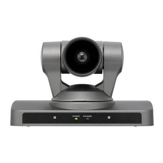
リモコン(1) 各部の名称と働き カメラ本体 前面 取扱説明書(1) A レンズ 光学 10 倍ズームレンズです。 B リモコン受光部 付属のリモコンの受光部です。 C POWER ランプ AC 電源アダプターと電源コードを 使って本機をコンセントにつなぐ と、点灯します。 付属リモコンからの操作を受信する と、緑色が点滅してお知らせしま す。 D STANDBY ランプ リモコンで電源を切ると、点灯しま す。 各部の名称と働き... -
Page 11: Visca Out
I VISCA OUT 端子 背面 複数のカメラを接続するとき、次の カメラの VISCA IN 端子と接続しま す。 J VIDEO OUT 端子 本機からの映像をアナログコンポー ネント信号として出力します。デジ タル信号も、この端子から出力しま す。 底面 E DC IN 12 V 端子 付属の AC 電源アダプターを接続し ます。 F SYSTEM SELECT スイッチ VIDEO OUT 端子から出力する映 像信号の出力方式の設定に使用しま す。 詳しくは、 「SYSTEM SELECT ス イッチの設定」... - Page 12 重要 スイッ 映像出力形式 EVI-HD7V EVI-HD3V 機器の名称と電気定格は、底面に表示さ チ位置 (ビデオ 対応 対応 れています。 フォーマット) 1920 × 1080p/ SYSTEM SELECT スイッチの設定 ○ × 59.94 本スイッチを使用して、VIDEO OUT 1920 × 1080p/ ○ × 端子から出力する映像出力方式(ビデ 29.97 オフォーマット)を設定できます。 1920 × 1080i/ ○ × 59.94 Hz 59.94 ご注意...
-
Page 13: リモコン
C スイッチ 3(Sync 切り換えス ご注意 イッチ) ・ スイッチ位置が「出力なし」の場合は、 VIDEO OUT 端子から出力されるア POWER ランプと STANDBY ランプの ナログ映像信号に対して、Sync を 両方が点灯した状態になります。この 付加する/しないを設定できます。 場合はリモコンと VISCA 通信の両方で 接続されるモニターがアナログ入力 制御できません。 の場合に使用してください。特に ・ VISCA CONTROL では、外部通信でビ HD/VD を接続しない場合は Sync デオフォーマットの設定ができますが、 を付加する設定にしてください。 映像が出力されるまでには他のスイッ チ位置よりも時間が多くかかります。 D スイッチ 4(未使用) 詳しくはテクニカルマニュアルを参照 常に... -
Page 14: Back Light
ご注意 ご注意 近くに同じカメラ番号に設定したカメ メニュー表示中は、パン・チルト操作 ラがある場合、付属のリモコンで同時 はできません。 に動作してしまいます。近くに設置す D PAN-TILT ボタン るカメラは、違うカメラ番号に設定す 矢印ボタンを押して、パン・チルト ることをお勧めします。 します。HOME ボタンを押すと、 カメラ番号の設定のしかたは、 「複数 カメラの向きが正面に戻ります。 のカメラをリモコンで操作する」 (27 メニューが表示されているときは、 ページ)をご覧ください。 V または v ボタンでメニュー項目を B FOCUS ボタン 選び、B または b ボタンで設定値 ピント合わせに使います。 を変更します。メインメニューが表 示されているときは、HOME ボタ 自動でピントを調節するときは ンを押すと、選んだ項目の設定メ AUTO ボタンを押します。手動で ニューが表示されます。... - Page 15 記憶を消すときは、RESET ボタン を押しながら、1 ∼ 6 ボタンを押し ます。 I PAN-TILT RESET ボタン パン・チルト位置をリセットしま す。 J ZOOM ボタン ゆっくりズームするときは SLOW ボタンを、すばやくズームするとき は FAST ボタンを使います。 T ボタンを押すと被写体が大きくな り、W ボタンを押すと被写体が小 さくなります。 リモコンの電池を入れるには 単 3 形乾電池 2 個(別売り) ご注意 破裂の危険性があるため、必ず単3形の マンガン乾電池またはアルカリ乾電池を ご使用ください。 各部の名称と働き...
-
Page 16: メニュー画面の見かた
B メニューで行う調整と設定 b メニュー項目 メニュー画面の見か リモコンの V または v ボタンで設 定メニューを選択し、HOME ボタ た ンを押すと、選んだ設定メニューが 本機では、撮影の条件や本機のシステ 表示されます。 ムセットアップなどを、外部モニター の画面に表示されるメニューを見なが 設定メニュー ら設定できます。 メインメニューで選択した設定メ 実際の操作を始める前にメニュー画面 ニューが表示されます。 の見かたを説明します。 メニュー画面全体の構成については、 「メニューの構成」 (37 ページ)をご覧 ください。 ご注意 メニュー表示中は、パン・チルト操作は できません。 a 設定メニュー メインメニュー 現在選択されているメニュー名が表 示されます。 付属のリモコンの DATA SCREEN ボ タンを押すと、メインメニューが表示... -
Page 17: 操作ボタン表示部
d 設定値 設定画面 現在設定されている設定値が表示さ れます。 リモコンの B または b ボタンで設 定を変更します。 各設定項目の初期設定値について は、 「メニューの構成」 (37 ページ) をご覧ください。 1 リモコンの V または v ボタンで設定 操作ボタン表示部 項目を選び、B または b ボタンで 設定値を変更できることを示してい 画面に表示される名称と、リモコンの ます。 ボタンの名称が異なります。下図を参 2 DATA SCREEN ボタンを押すと、 照して、リモコンのボタンを押してく メインメニューへ戻ることを示して ださい。 います。 メインメニュー... -
Page 18: メニューの操作のしかた
メニューの操作のし かた ここでは、付属のリモコンを使った操 作のしかたを説明します。 各メニューについて詳しくは、19 ∼ 23 V または v ボタンを押して、変更 ページをご覧ください。 したい設定項目にカーソルを合わ せる。 B または b ボタンを押して、設定 値を変更する。 DATA SCREEN ボタンを押す。 メインメニューが表示されます。 ご注意 付属のリモコンでメニューを操作してい る場合は、SYSTEM メニューの IR- RECEIVE を OFF に設定することはでき ません。IR-RECEIVE を OFF にするに は、VISCA コマンドをご使用ください。 VISCA コマンドリストについては、テク ニカルマニュアルを参照してください。... -
Page 19: Exposure メニュー
GAIN:感度を選択します。 EXPOSURE メ –3、0、3、6、9、12、15、18 dB から選択できます。 ニュー SPEED:電子シャッターのシャッ タースピードを選択します。 露出調整のメニューです。 信号フォーマットが 59.94/ 29.97 のとき 1/60、1/90、1/100、1/125、 1/180、1/250、1/350、1/500、 1/725、1/1000、1/1500、1/2000、 1/3000、1/4000、1/6000、 1/10000 から選択できます。 信号フォーマットが 50/25 の MODE(露出モード) とき 1/50、1/75、1/100、1/120、 FULL AUTO:感度、電子シャッター、 絞りをすべて使用して、露出を自 1/150、1/215、1/300、1/425、 1/600、1/1000、1/1250、1/1750、 動調整します。 1/2500、1/3500、1/6000、 BRIGHT:ブライトレベル(LEVEL) を調整します。 1/10000 から選択できます。 IRIS:絞りを選択します。 SHUTTER Pri:感度と絞りを使用し CLOSE、F26、F22、F19、F16、... -
Page 20: White Balance メニュー
EX-COMP(露出補正) WHITE BALANCE MODE(露出モード)が FULL AUTO、SHUTTER Pri、SPOT メニュー LIGHT、IRIS Pri のとき ON にすると、 露出補正ができます。EX-COMP を ホワイトバランス調整メニューです。 ON にすると LEVEL(露出補正レベ ル)が表示されます。 –7、–6、–5、–4、–3、–2、–1、0、+1、 +2、+3、+4、+5、+6、+7 から選択で きます。 0 は露出補正されません。+7 は最も明 るく、–7 は最も暗く設定されます。 OFF は露出補正機能が働きません。 MODE(ホワイトバランスモード) ホワイトバランスモードを選択します。 AUTO(自動) 、INDOOR(室内) 、 OUTDOOR(屋外) 、ONE PUSH(ワ ンプッシュ) 、MANUAL(手動)から 選択できます。... -
Page 21: Picture メニュー
PICTURE メニュー PAN TILT ZOOM メニュー パン・チルト・ズーム用のメニューで す。 APERTURE(輪郭補正) 輪郭補正レベルを選択します。 MIN、1 ∼ 14、MAX から選択できま す。 PAN/TILT LIMIT(パン・チルト制 限) PAN/TILT LIMIT を ON にするとパ ン・チルト範囲の制限ができます。以 下の設定値を選択できます。 RIGHT:+100°∼ –100°まで、1°ご とに選択可能。 LEFT:–100°∼ +100°まで、1°ごと に選択可能。 UP:+25°∼ –25°まで、1°ごとに選 択可能。 DOWN:–25°∼ +25°まで、1°ごと に選択可能。 LEFT/RIGHT の設定範囲 CENTER(± 0°) –... -
Page 22: System メニュー
ご注意 SYSTEM メニュー PAN/TILT LIMIT(パン・チルト制限) は、設定後すぐに反映されます。また電 源を 1 度切ってから再度入れたときに、 電源を切る前の状態を反映させたいとき は、POSITION 1に設定を記憶させてく ださい。 詳しくは、 「カメラの状態を記憶させる− プリセット機能」 (28 ページ)をご覧く ださい。 IR-RECEIVE(赤外線受光) UP/DOWN の設定範囲 OFF にすると、付属のリモコンの信号 を受け付けなくなります。 +25° 付属のリモコンを使うときは、必ず ± 0° ON にしてください。 – 25° ご注意 付属のリモコンでメニューを操作してい る場合は、IR-RECEIVE を OFF に設定 ご注意 することはできません。IR-RECEIVE を... -
Page 23: Status メニュー
メッセージ リモコンでの操作 STATUS メニュー RESET n : OK POSITION 1 ∼ 6 に (n はリセットの 記憶させた値をリセッ メニューで設定した内容を一覧表示し ポジション番号 トしたとき。 ます。 1 ∼ 6) One Push WB : ワンプッシュオートホ ワイトバランスが実行 されているときに点滅 で表示。 One Push WB : ワンプッシュオートホ ワイトバランスが正常 に終了したときに点灯 で表示。 STATUS メニューは PAGE1 ∼ One push WB : ワンプッシュオートホ... -
Page 24: 操作を始める前に
B 付属のリモコンを使った操作 操作を始める前に 電源を入れる 操作を行う前に、本機および周辺機器 が正しく設置、接続されていることを 確認してください。 詳しくは、 「SYSTEM SELECT スイッ チの設定」 (12 ページ)および「設置 する」 (30 ページ) 、 「接続する」 (31 DC IN12 V 端子 ページ)をご覧ください。 コンセントへ ご注意 インバータ式の照明器具の近くでは、ご くまれにリモコンが作動しないことがあ ります。そのような場合は、本機を、該 当照明器具から離れたところに設置する などの処置を試みてください。 リモコンが安定して動作できる環境かを 判定して確認する方法があります。 POWER 点灯 詳しくはテクニカルマニュアルを参照し 付属の AC 電源アダプターと電源 てください。... -
Page 25: パン・チルト・ズームを 操作する
リモコンで電源を切ると、POWER ラ パン・チルト・ズー ンプは消え、STANDBY ランプが点灯 します。 ムを操作する パン・チルトする POWER STANDBY 点灯 POWER スイッチを押す。 電源が入って、カメラは自動的にパ ン・チルトリセット動作をします。 矢印ボタンを押してパン・チルト する。 画面を見ながら、見たい方向の矢印 ボタンを押します。 細かく動かすには:短く押します。 大きく動かすには:長く押し続けま す。 斜めに動かすには:V または v ボ タンを押しながら、B または b ボ タンを押します。 カメラの向きを正面に戻すには HOME ボタンを押します。 カメラの向きを手で動かしてしまい STANDBY ランプが点滅したら PAN-TILT RESET ボタンを押してパ ン・チルト位置をリセットします。... -
Page 26: ズームする
カメラの動きと見たい方向の矢印ボタ カメラの STANDBY ランプが点滅し ンが違うときは たら 通常、b ボタンを押すと、カメラから 出力される映像が、右方向に動くよう に設定されています。 カメラの動きを左右逆にしたい場合: 画面を見ながらカメラの向きを変える ときなど、カメラの動きを左右逆にし STANDBY 点滅 たい場合は、L/R DIRECTION SET ボ 外力でカメラが動かされたときや、物 タンを押しながら 2(REV)ボタンを や指をはさんだ場合など、カメラのマ 押します。 イコンがカメラのパン・チルト位置を 矢印ボタン カメラの動き 設定方法 正しく記憶していないことがあり、カ メラの動きが自動停止します。 PAN-TILT RESET ボタンを押してパ 押しながら ン・チルト位置をリセットするか、1 度電源を切り、再度電源を入れてくだ 押す さい。 もとの設定に戻すときは: ズームする L/R DIRECTION SET ボタンを押しな... -
Page 27: 複数のカメラをリモコンで 操作する
複数のカメラをリモコンで操作 カメラを調節する する 操作したいカメラ後面の IR SELECT スイッチを 1、2、3 のどれかに合わせる。 手順 1 で設定した番号と同じ番号 の CAMERA SELECT ボタン (リモコン)を押す。 ピントを合わせる 自動でピントを調節するには CAMERA SELECT AUTO ボタンを押します。 自動的に画面中央部の被写体にピント が合います。 これで、特定のカメラをリモコンから 手動でピントを調節するには 操作できるようになります。 リモコンからカメラを操作するたびに、 MANUAL ボタンを押してから、FAR 手順 2 で押した CAMERA SELECT ボ ボタンまたは NEAR ボタンで調節しま タンが点灯します。... -
Page 28: 逆光を補正する
逆光を補正する カメラの状態を記憶 被写体の背後に光源があり、被写体が させる −プリセット機能 暗く映る場合など BACK LIGHT ボタ ンを押します。 カメラの向きや、ズーム、ピント調節、 解除するには、もう一度 BACK 逆光補正の入切などを 6 種類まで記憶 LIGHT ボタンを押します。 できます。 記憶できる設定項目については、 「プリ セット項目」 (40 ページ)をご覧くだ さい。 被写体が明るく 映る ご注意 BACK LIGHT ボタンは、EXPOSURE メ ニューの MODE を MANUAL に設定し た場合無効となります。 PAN-TILT RESET ボタンを押し てパン・チルト位置をリセットす... - Page 29 タンの番号「RESET n: OK」が約 3 秒 間表示されます。 ご注意 設定したいボタン ・ 電源を入れたときは、POSITION 1 に を押す 記憶された設定内容で起動します。 押しながら ・ 電源を一度切ってから再度入れたとき に、電源を切る前のカメラの状態やパ ン・チルト位置を反映させたいときは、 SYSTEM メニューで、DISPLAY POSITION 1 に設定を記憶させてくだ INFO(22 ページ参照)を ON に設 さい。 定しておくと、選んだ PRESET ボ ・ POSITION 1 への記憶設定、記憶消去 タンの番号「PRESET n: OK」が約 は、他の POSITION よりも、2 秒程度 3 秒間表示されます。...
-
Page 30: 設置する
B 設置と接続 ・ カメラヘッド部をパン方向やチルト方 設置する 向へ手で回さないでください。故障の 原因となります。 設置は確実に 設置については、必ずお買い 上げ店またはソニーのサービ ス窓口にご相談ください。 設置は、本機と取り付け金具 を含む重量に充分耐えられる 強度があることをお確かめく ださい。充分な強度がない と、落下して、大けがの原因 となります。 三脚に取り付ける また、一年に一度は、取り付 けがゆるんでいないかを点検 底面の三脚取り付け用ネジ穴に三脚を してください。 取り付けます。 三脚は、段差のない平面に取り付け、 デスクトップへ設置する 手でしっかり締め付けてください。 カメラ本体は、平らなところに置きま 三脚取り付け用のネジは、次の規格の す。 ものを使用してください。 やむを得ず傾いたところに設置すると -20UNC きは、パン・チルト動作性能を保証す るため、水平に対して± 15°以内のと ころに設置し、落下防止処置を施して 4 = 5.5 mm ください。... -
Page 31: 固定用ネジを使って取り付ける
固定用ネジを使って取り付ける 接続する 底面の取り付け用ネジ穴(M3)3 箇所 を使って固定します。M3 ネジは、次 AC 電源への接続 の規格のものを使用してください。ネ ジは、金具などの段差のない平面に取 付属の AC 電源アダプターと電源コー り付け、しっかり締めてください。 ドを使って、AC 電源へ接続します。 M3 ネジ 4 = 3 mm ∼ 5 mm 電源コン セントへ DC IN12 V AC 電源アダプター (付属) 電源コード(付属) 警告 本機は電源スイッチを備えていません。 設置の際には、容易にアクセスできる固 定配線内に専用遮断装置を設けるか、使 用中に、容易に抜き差しできる、機器に 近いコンセントに電源プラグを接続して ください。... -
Page 32: コンピューターとの接続
コンピューターとの接続 アナログコンポーネント入力端 子を持つモニターなどとの接続 VISCA IN 電源コンセントへ VIDEO OUT 電源コンセントへ VISCA ケーブル (別売り) DVI- コンポーネン ト変換ケーブル (別売り) RS-232C 入力へ コンポーネント 入力端子へ コンピューター HD ビデオモニターなど ご注意 VISCA ケーブル(RS-232C クロスタイ ご注意 プ)を接続すると、付属のリモコンの HD モニターの仕様に合わせて、 かわりにコンピューターでも操作でき COLOR SYSTEM、VIDEO ます。VISCA ケーブルについては、お FORMAT、Sync 切り換えスイッチ 買い上げ店にご相談ください。接続方 (BOTTOM スイッチ 3)の設定をして 法、コマンドリストについては、テク... -
Page 33: アナログ Rgb 入力端子を持つ モニターなどとの接続
アナログ RGB 入力端子を持つ DVI 入力端子を持つモニターな モニターなどとの接続 どとの接続 VIDEO OUT VIDEO OUT 電源コンセントへ 電源コンセントへ DVI- アナログ DVI ケーブル RGB 変換ケーブル (別売り) (別売り) アナログ RGB DVI 入力 入力端子へ 端子へ HD ビデオモニターなど HD ビデオモニターなど ご注意 ご注意 HD モニターの仕様に合わせて、 ・ HD モニターの仕様に合わせて、 COLOR SYSTEM、VIDEO COLOR SYSTEM、VIDEO FORMAT、Sync 切り換えスイッチ... -
Page 34: メッセージ一覧
B 付録 メッセージ一覧 本機に表示されるメッセージは、以下のとおりです。必要に応じて次に示す処置を 行ってください。 ランプ表示 ランプ 意味と対策 STANDBY ランプと この状態で本機を使用すると故障の原因になります。この場合は、 POWER ランプが交互に STATUS メニューの PAGE4 に「COOLING FAN:NG」が表示がさ ゆっくり点滅 れます。本機の電源を切り、お買い上げ店またはソニーのサービス 窓口にご連絡ください。 STANDBY ランプと SYSTEM SELECT スイッチが「出力なし」に設定されています(12 POWER ランプが点灯 ページ) 。 画面表示 メッセージ 意味と対策 CAUTION COOLING FAN この状態で本機を使用すると故障の原因になります。本機の電源を STOPPED! 切り、お買い上げ店またはソニーのサービス窓口にご連絡ください。 (起動直後に表示) PRESET n:OK POSITION 1 ∼... -
Page 35: 故障かな?と思ったら
故障かな?と思ったら 故障とお考えになる前に下記の項目をもう一度チェックしてみてください。それで も具合の悪いときは、ソニーのサービス窓口にご相談ください。 症状 原因 処置 電源が入らない。 AC 電源アダプターが DC IN 奥までしっかり差し込んでください。 12 V 端子にしっかり接続されて いない。 電源コードが AC 電源アダプター 奥までしっかり差し込んでください。 や電源コンセントにしっかり接続 されていない。 接続したビデオモニ 映像接続ケーブルが正しく接続さ 本機とビデオモニターの接続を確認し ターに画像が出ない。 れていない。 てください。 カメラの露出が正しく設定されて EXPOSURE メニューで露出の設定を いない。 確認してください(19 ページ) 。 SYSTEM SELECT スイッチが正 本機の出力ビデオフォーマットとビデ しく設定されていない。 オモニターの入力ビデオフォーマット... - Page 36 症状 原因 処置 コンピューターに接続 コンピューターが正しく接続され 本機とコンピューターの接続を確認し しても VISCA 通信が ていない。 てください。 できない。 カメラ底面の BOTTOM スイッチ (13 ページ)で VISCA 通信のボー レート(9,600 bps または 38,400 bps) が正しく設定されているか確認してく ださい。 SYSTEM SELECT スイッチ(12 ページ)が、映像信号が出力される位 置になっているかを確認してくださ い。 どうしても動作しない。 ― 電源コードのプラグをコンセントから 抜き、しばらくしてからもう一度つな いでみてください。 故障かな?と思ったら...
-
Page 37: メニューの構成
メニューの構成 本機のメニューは次のように構成されています。詳しい内容は、 ( )内のページを ご覧ください。 各項目の初期設定値は、太字で示しています。 (19 ページ) メニューの構成... - Page 38 (20 ページ) (21 ページ) (21 ページ) (22 ページ) メニューの構成...
- Page 39 (23 ページ) メニューの構成...
-
Page 40: プリセット項目
プリセット項目 カメラ内部のメモリーには、次の、付属のリモコンを使っての調整、およびメ ニューの設定項目が記憶されます。 リモコンを使っての調整 プリセットできる項目 プリセットポジション番号 パン・チルト位置 ◎ ○ ○ ○ ○ ○ ズーム位置 ◎ ○ ○ ○ ○ ○ フォーカス オート/マニュアル ◎ ○ ○ ○ ○ ○ フォーカス位置 ◎ ○ ○ ○ ○ ○ 逆光補正オン/オフ ◎ ○ ○ ○ ○... - Page 41 下記の項目はメモリー(ポジション 1)に記憶できますが、VISCA のみで設定可能 です。 ・ Focus Near Limit ・ IR Receive ・ IR Receive Return VISCA コマンドリストについては、テクニカルマニュアルを参照してください。テ クニカルマニュアルについては、お買い上げ店にお問い合わせください。 プリセット項目...
- Page 42 パン・チルト機能 仕様 水平± 100° 最大速度:300°/秒 垂直± 25° システム 最大速度:125°/秒 映像信号 EVI-HD7V:1920 × 1080p/ 59.94、1920 × 1080p/50、 入出力端子 1920 × 1080p/29.97、1920 映像出力 COMPONENT(VIDEO × 1080p/25、1920 × 1080i/ OUT) :DVI-I 端子 59.94、1920 × 1080i/50、 Y:1 Vp-p(同期付き、 1280 × 720p/59.94、1280 × 75 Ω 終端時)...
- Page 43 付属品 AC 電源アダプター(1) 電源コード(1) リモコン(1) 取扱説明書(1) 注意 付属の電源コードは本機の専用品です。 他の機器には使用できません。 本機の仕様および外観は、改良のため 予告なく変更することがありますが、 ご了承ください。 この装置は、クラス A 情報技術装置 です。この装置を家庭環境で使用す ると電波妨害を引き起こすことがあ ります。この場合には使用者が適切 な対策を講ずるよう要求されること があります。 VCCI-A お使いになる前に、必ず動作確認を 行ってください。故障その他に伴う 営業上の機会損失等は保証期間中お よび保証期間経過後にかかわらず、 補償はいたしかねますのでご了承く ださい。 仕様...
- Page 44 寸法図 上面 背面 正面 側面 底面 深さ 5 以下 深さ 3 から 5 深さ 5 から 7 単位:mm 仕様...
- Page 45 VIDEO OUT 端子 端子のピン配列 (DVI 29 ピン) VISCA IN 端子 PLUG & PLAY (8 ピンミニ DIN、凹) TMDS アナログ ピン番号 機能 ピン番号 機能 DTR IN Data_2 − DSR IN Data_2 + TXD IN Shield(2、4) 未使用 RXD IN 未使用 未使用 * IR OUT(R) 未使用...
-
Page 46: 保証とアフターサービスに ついて
保証とアフターサー ビスについて 調子が悪いときはまずチェックを この取扱説明書をもう一度ご覧になっ てお調べください。 保証期間と保証条件 本機の保証期間および保証条件は、販 売地域(国内、海外)によって異なる ことがあります。お手数ですが、お買 い上げ店にお問い合わせ、ご確認いた だきますようお願い申し上げます。 保証とアフターサービスについて... - Page 47 The nameplate is located on the bottom. For the customers in Europe For the customers in the U.S.A. The manufacturer of this product is Sony This equipment has been tested and found to Corporation, 1-7-1 Konan, Minato-ku, comply with the limits for a Class A digital Tokyo, Japan.
- Page 48 Sony. For the customers in Korea Pour les clients en Europe SONY LIMITED WARRANTY - Please Le fabricant de ce produit est Sony visit http://bpeng.sony.co.kr/handler/ Corporation, 1-7-1 Konan, Minato-ku, BPAS-Start for important information and Tokyo, Japon.
- Page 49 Sollten Funkstörungen auftreten, wenden Sie sich bitte an den nächsten autorisierten Sony-Kundendienst. Für Kunden in Europa Der Hersteller dieses Produkts ist Sony Corporation, 1-7-1 Konan, Minato-ku, Tokyo, Japan. Der autorisierte Repräsentant für EMV und Produktsicherheit ist Sony Deutschland...
- Page 50 Table of Contents Panning and Tilting ....69 Getting Started Zooming ........70 Operating Multiple Cameras Precautions ........51 with the Remote Phenomena Specific to CMOS Image Commander ....71 Sensors ..........52 Adjusting the Camera ...... 71 Focusing on a Subject ....71 Overview Shooting with Back Lighting ..
-
Page 51: Getting Started
Operating or storing the camera in the maintenance. If abnormal noise occurs, following locations may cause damage to consult your Sony dealer. the camera: • Extremely hot or cold places (Operating temperature: 0 °C to 40 °C Note on laser beams [32 °F to 104 °F]) -
Page 52: Phenomena Specific To Cmos Image Sensors
Phenomena Specific to CMOS Image Sensors The following phenomena that may appear in images are specific to CMOS (Complementary Metal Oxide Semiconductor) image sensors. They do not indicate malfunctions. White flecks Although the CMOS image sensors are produced with high-precision technologies, fine white flecks may be generated on the screen in rare cases, caused by cosmic rays, etc. -
Page 53: Overview
Video format compatible with 60/50 Hz progressive scan The EVI-HD7V camera allows you to shoot moving objects in Full HD progressive scan for high-resolution image output. The EVI-HD7V also allows output in the interlaced format used in HDTV broadcasts. -
Page 54: Location And Functions Of Parts And Controls
European model Location and Functions of Parts and Controls Camera Front Remote commander (1) Operating Instructions (1) A Lens This is a 10-magnification optical zoom lens. B Remote sensors These are sensors for the supplied remote commander. C POWER lamp Lights when the camera is connected to an AC outlet using the supplied AC power adaptor and AC power cord. - Page 55 Rear Bottom E DC IN 12 V connector K BOTTOM switches Connect the supplied AC power adaptor. Used for RS-232C baud rate selection, turning the remote control signal output F SYSTEM SELECT switch on/off, and selecting whether to add sync. Used for selecting the video format of the signal to be output from the VIDEO For details, see “Setting of the...
- Page 56 1280×720p/ 59.94 For detailed information, refer to the 1280×720p/ Technical Manual of the camera. For details 29.97 on obtaining a Technical Manual, consult your Sony dealer. 640×480p/ 59.94(LB) No output – – – VISCA – CONTROL...
-
Page 57: Remote Commander
Setting of the BOTTOM switches Remote Commander (supplied) A Switch 1 (infrared remote commander signal output switch) Set to ON to enable output of the receiver signals, that are transmitted from the remote commander, from the VISCA IN connector (page 88), or set it to OFF to disable the output. -
Page 58: Back Light Button
G BACK LIGHT button Press this button to enable the backlight Note compensation. Press it again to disable Press the MANUAL button and adjust the backlight compensation. the focus manually when shooting the following objects. H POSITION buttons • White walls and other objects without Hold down the PRESET button and press contrast button 1 to 6 to store the current camera... - Page 59 ATTENTION Il y a danger d’explosion s’il y a remplacement incorrect de la batterie. Remplacer uniquement avec une batterie du même type ou d’un type équivalent recommandé par le constructeur. Lorsque vous mettez la batterie au rebut, vous devez respecter la législation en vigueur dans le pays ou la région où...
-
Page 60: Adjusting And Setting With Menus
Adjusting and Setting with Menus About On-Screen Setting Menus Menus The setting menu selected on the main menu is displayed. You can change various settings, such as shooting conditions and system setup of the camera, while observing menus displayed on a connected monitor. This section explains how to read the on- screen menus before starting menu operations. -
Page 61: Operating The Camera Using Menus
Main menu Operating the Camera Using Menus This section explains how to perform operations using the supplied remote commander. For details on each menu, see page 63 to page 67. a Indicates that you should use the V or v button on the remote commander to select the setting menu. - Page 62 For detailed information on how to connect and VISCA command list, refer to the Technical Manual of the camera. For details on obtaining a Technical Manual, consult your Sony dealer. To return to the main menu Press the DATA SCREEN button. Operating the Camera Using Menus...
-
Page 63: Exposure Menu
For the 59.94/29.97 video format: EXPOSURE Menu 1/60, 1/90, 1/100, 1/125, 1/180, 1/250, 1/350, 1/500, 1/725, 1/1000, 1/1500, 1/2000, 1/3000, 1/4000, 1/6000, The EXPOSURE menu is used to set the 1/10000 sec. items related to the exposure. For the 50/25 video format: 1/50, 1/75, 1/100, 1/120, 1/150, 1/215, 1/300, 1/425, 1/600, 1/1000, 1/1250, 1/1750, 1/2500, 1/3500, 1/6000,... -
Page 64: White Balance Menu
WHITE BALANCE PICTURE Menu Menu The WHITE BALANCE menu is used to select the white balance mode. APERTURE (aperture compensation) Select the aperture compensation level from among MIN, 1 to 14 and MAX. MODE (white balance mode) Select the white balance mode from among the following: AUTO, INDOOR, OUTDOOR, ONE PUSH, MANUAL... -
Page 65: Pan Tilt Zoom Menu
turning off the power, store those values in PAN TILT ZOOM POSITION 1. Menu For details, see “Storing the Camera Settings in Memory — the Presetting Feature” (page 72). The PAN TILT ZOOM menu is used to select the pan/tilt/zoom mode. Setting the range of UP/DOWN movement +25°... -
Page 66: System Menu
VISCA command list, refer to the Technical Manual of the camera. For details on obtaining a Technical Manual, consult your Sony dealer. DISPLAY INFO When this item is set to ON, the message automatically appears for about 3 seconds... -
Page 67: Status Menu
STATUS Menu The STATUS menu is used to display the settings selected with the menus. The STATUS menu consists of PAGE1 to PAGE4. This menu only displays the current menu settings, and you cannot change them with this menu. PAGE1: Shows the settings selected with the EXPOSURE menu. -
Page 68: Operation Using The Supplied Remote Commander
For detailed information on how to check, refer to the Technical Manual. For details on obtaining a Technical Manual, consult your Sony dealer. POWER lights. Connect the camera to an AC outlet using the supplied AC power adaptor and power cord. -
Page 69: Pan/Tilt And Zoom Operation
off and the STANDBY lamp lights on the Pan/Tilt and Zoom camera. Operation Panning and Tilting POWER STANDBY lights. Press the POWER switch. The camera will turn on and perform the pan/tilt reset operation automatically. Press the arrow button to pan or tilt the camera. -
Page 70: Zooming
If the camera moves in a different If the STANDBY lamp of the camera direction from the one you intended flashes The camera is preset so that the image output from the camera is rotated toward the right whenever you press the b button. To face the camera toward the opposite direction: You might wish to face the camera toward... -
Page 71: Operating Multiple Cameras
Operating Multiple Cameras Adjusting the with the Remote Commander Camera Set the IR SELECT switch on the rear of the camera you want to operate to 1, 2 or 3. Press the CAMERA SELECT button on the remote commander that corresponds to the number set in step Focusing on a Subject CAMERA... -
Page 72: Storing The Camera Settings In Memory - The Presetting Feature
To cancel the function, press the BACK Storing the Camera LIGHT button again. Settings in Memory — the Presetting Feature Subject Up to six combinations of settings (six appears positions) including camera position, brighter. zooming, focusing, and backlighting, can be preset. - Page 73 • Storing or cancelling the settings in POSITION 1 takes about 2 seconds longer than those of other positions. • When you are storing or cancelling the Press a POSITION settings in one POSITION, you cannot call button. up, store or cancel the settings in another While holding POSITION.
-
Page 74: Installation And Connection
Installation and Connection Installing the Attaching the Camera to a Tripod Camera Attach a tripod to the screw hole used for attaching a tripod on the bottom of the camera. Installing the Camera on a The tripod must be set up on a flat surface Desk and its screws tightened firmly by hand. -
Page 75: Connections
To obtain a cable, consult your Sony dealer. For detailed information on how to connect the camera and the VISCA command list, refer to the Technical Manual of the camera. -
Page 76: Connecting A Video Monitor, Etc
Connecting a Video Monitor, Connecting a Video Monitor, etc., Equipped with an Analog etc., Equipped with an Analog Component Input Connector RGB Input Connector VIDEO OUT VIDEO OUT to AC outlet to AC outlet DVI to analog RGB DVI to component adapter cable adapter cable (not (not supplied) -
Page 77: Connecting A Video Monitor, Etc
Connecting a Video Monitor, etc., Equipped with a DVI Input Connector VIDEO OUT to AC outlet DVI cable (not supplied) to DVI input connector HD Video monitor, etc. Notes • Configure the COLOR SYSTEM and VIDEO FORMAT based on the specifications of the HD monitor. -
Page 78: Appendix
POWER lamp flash slowly case, “COOLING FAN:NG” appears on PAGE4 of the STATUS in alternation. menu. Turn off the camera, and consult your Sony dealer. The STANDBY lamp and The SYSTEM SELECT switch is set to “no output” (page 55). -
Page 79: Troubleshooting
Troubleshooting Before bringing in your camera for service, check the following as a guide to troubleshooting the problem. If the problem cannot be corrected, consult your Sony dealer. Symptom Cause Remedy The power of the camera is The AC power adaptor is not Insert the power cord firmly as not turned on. - Page 80 Symptom Cause Remedy The VISCA control is not The computer is not correctly Make sure the connection available with a computer connected to the camera. between the computer and connected to the camera. camera is made correctly. Check that the baud rate setting (9,600 bps or 38,400 bps) is properly made with the BOTTOM switch on the bottom...
-
Page 81: Menu Configuration
Menu Configuration The menus of the camera are configured as described below. The initial settings of each item are in bold. (See page 63.) Menu Configuration... - Page 82 (See page 64.) (See page 64.) (See page 65.) Initial setting: +100° Initial setting: -100° Initial setting: +025° Initial setting: -025° (See page 66.) Menu Configuration...
- Page 83 (See page 67.) Menu Configuration...
-
Page 84: Preset Items
Preset Items The following items set by using the remote commander and menu items can be stored in the memory of the camera. Items adjusted with the remote commander Preset item Preset position number Pan/Tilt Position Zoom Position Focus Mode Auto/Manual Focus Position Backlight Compensation ON/OFF Menu items... - Page 85 • Focus Near Limit • IR Receive • IR Receive Return For detailed information on the VISCA command list, refer to the Technical Manual of the camera. For details on obtaining a Technical Manual, consult your Sony dealer. Preset Items...
-
Page 86: Specifications
Note Vertical: ±25 degrees Maximum tilting speed: Always verify that the unit is operating 125 degrees/sec. properly before use. SONY WILL NOT BE LIABLE FOR DAMAGES OF ANY Input/output connectors KIND INCLUDING, BUT NOT LIMITED TO, COMPENSATION OR Video output... - Page 87 Dimensions Back Front Side Bottom Within a depth from 5 mm (7/32 inches) or less from the bottom surface. Within a depth from 5 to 7 mm (7/32 to 9/32 inches) from the bottom surface. Within a depth from 3 to 5 mm (1/8 to 7/32 inches) 66 (2 66 (2...
- Page 88 VIDEO OUT connector (DVI 29-pin) Pin assignments PLUG & PLAY VISCA IN connector (mini-DIN 8-pin, TMDS ANALOG female) Pin No. Function Data_2 – Pin No. Function Data_2+ DTR IN Shield (2, 4) DSR IN No connection TXD IN No connection No connection RXD IN No connection...
- Page 89 Specifications...
- Page 90 Specifications...
- Page 91 Specifications...
- Page 92 Sony Corporation...