Toro 74920 TITAN ZX4820 Operator's Manual
Zero-turn-radius riding mower
Hide thumbs
Also See for 74920 TITAN ZX4820:
- Manual (8 pages) ,
- Operator's manual (64 pages) ,
- Operator's manual (56 pages)

Related Manuals for Toro 74920 TITAN ZX4820


Summary of Contents for Toro 74920 TITAN ZX4820
- Page 1 Form No. 3375-781 Rev A TITAN ZX4820 or ZX5420 Zero-Turn-Radius Riding Mower Model No. 74920—Serial No. 313000001 and Up Model No. 74924—Serial No. 313000001 and Up *3375-781* A Register at www.Toro.com. Original Instructions (EN)
-
Page 2: Introduction
This manual uses 2 other words to highlight information. Important calls attention to special mechanical information You may contact Toro directly at www.Toro.com for product and Note emphasizes general information worthy of special and accessory information, help finding a dealer, or to register attention. -
Page 3: Table Of Contents
Servicing the Cutting Blades........43 Rotary Lawnmower Machines ....... 4 Mower Deck Leveling ..........46 Safe Operating Practices........... 4 Inspecting the Belts ..........47 Toro Riding Mower Safety ........5 Replacing the Mower Belt ........47 Model 74920............6 Removing the Mower..........48 Model 74924............6 Installing the Mower ..........49... -
Page 4: Safety
Preparation Safety • While mowing, always wear substantial footwear and long trousers. Do not operate the equipment when barefoot Safe Operation Practices or wearing open sandals. for Ride-on (riding) Rotary • Thoroughly inspect the area where the equipment is to be used and remove all objects which may be thrown by Lawnmower Machines the machine. -
Page 5: Toro Riding Mower Safety
Do not change the engine governor settings or overspeed the engine. Operating the engine at excessive speed can The following list contains safety information specific to Toro increase the hazard of personal injury. products or other safety information that you must know that •... -
Page 6: Model 74920
• Follow the manufacturer's recommendations for wheel Uncertainty Value (K) = 0.31 m/s2 weights or counterweights to improve stability. Measured values were determined according to the procedures • Use extreme care with grass catchers or other attachments. outlined in EN 836 (Riding & Stand-Ons). These can change the stability of the machine and cause loss of control. -
Page 7: Slope Indicator
Slope Indicator G011841 Figure 3 This page may be copied for personal use. 1. The maximum slope you can safely operate the machine on is 15 degrees. Use the slope chart to determine the degree of slope of hills before operating. Do not operate this machine on a slope greater than 15 degrees. Fold along the appropriate line to match the recommended slope. -
Page 8: Safety And Instructional Decals
Safety and Instructional Decals Safety decals and instructions are easily visible to the operator and are located near any area of potential danger. Replace any decal that is damaged or lost. 110-6691 1. Thrown object hazard—keep bystanders a safe distance from the machine. - Page 9 93-7009 1. Warning—do not operate the mower with the deflector up or removed; keep the deflector in place. 2. Cutting/dismemberment hazard of hand or foot, mower blade—stay away from moving parts. Battery Symbols Some or all of these symbols are on your battery 1.
- Page 10 Manufacturer's Mark 1. Indicates the blade is identified as a part from the original machine manufacturer. 114-1606 1. Entanglement hazard, belt—keep all guards in place. 115-9632 1. Power take-off (PTO), 5. Fast Blade control switch on some models 2. Blade control switch—On 6.
- Page 11 120-5466 1. Warning—read the Operator's Manual. 5. Loss of traction/control hazard, slopes—loss of traction/control on a slope, disengage the blade control switch (PTO), proceed off the slope slowly. 2. Warning—read the instructions before servicing or performing 6. Crushing/dismemberment hazard of bystanders, maintenance;...
- Page 12 115-9630 1. Read the Operator's Manual before performing any 4. Check the hydraulic oil every 25 hours maintenance. 2. Check the engine oil every 8 hours 5. Check the caster wheel tire pressure every 25 hours 3. Check the drive wheel tire pressure every 25 hours 6.
- Page 13 119-8986 1. Fuel 2. Full 4. Empty 3. Half...
-
Page 14: Product Overview
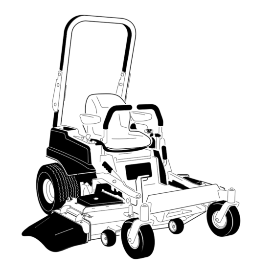
Product Overview G015763 Figure 4 1. Drive wheel 4. Motion control levers 7. Front caster wheel 10. Deflector 2. Operator seat 5. Parking brake 8. Anti-scalp roller 3. Roll over protection system 6. Footrest 9. Foot pedal deck lift and (ROPS) height-of-cut G014766... -
Page 15: Controls
It operates when the blade control switch (PTO) is its capabilities. Contact your Authorized Service Dealer or engaged. Use these times for scheduling regular maintenance Distributor or go to www.Toro.com for a list of all approved (Figure 6). attachments and accessories. -
Page 16: Operation
Using the Rollover Protection Operation System (ROPS) Note: Determine the left and right sides of the machine from the normal operating position. WARNING To avoid injury or death from rollover: keep the Think Safety First roll bar in the raised locked position and use the Please carefully read all of the safety instructions and decals seat belt. -
Page 17: Adding Fuel
G015035 DANGER In certain conditions during fueling, static electricity can be released causing a spark which can ignite the gasoline vapors. A fire or explosion from gasoline can burn you and others and can damage property. • Always place gasoline containers on the ground away from your vehicle before filling. -
Page 18: Filling The Fuel Tank
DANGER In certain conditions, gasoline is extremely flammable and highly explosive. A fire or explosion from gasoline can burn you and others and can damage property. • Fill the fuel tank outdoors, in an open area, when the engine is cold. Wipe up any gasoline g020264 that spills. -
Page 19: Checking The Engine Oil Level
Checking the Engine Oil Level Operating the Choke Before you start the engine and use the machine, check the oil Use the choke to start a cold engine. level in the engine crankcase; refer to Checking the Engine 1. If the engine is cold, use the choke to start the engine. Oil Level. -
Page 20: Starting And Stopping The Engine
G008947 Figure 17 2. Turn the ignition key to stop to stop the engine. Starting and Stopping the Engine Starting the Engine 1. Sit down on the seat (Figure 18) and fasten the seat belt. 2. Move the motion controls outward to the neutral lock G010080 position (Figure 18). -
Page 21: Operating The Mower Blade Control Switch (Pto)
Stopping the Engine Note: Engaging the blade control switch (PTO) with the throttle position at half or less will cause excessive wear to the drive belts. WARNING Children or bystanders may be injured if they move or attempt to operate the machine while it is unattended. -
Page 22: Driving Forward Or Backward
Using the Motion Control Levers with the parking brake on or if you rise from the seat when the blades are engaged. Testing the Safety Interlock System Test the safety interlock system before you use the machine each time. If the safety system does not operate as described below, have an Authorized Service Dealer repair the safety system immediately. -
Page 23: Stopping The Machine
Stopping the Machine WARNING Children or bystanders may be injured if they move or attempt to operate the machine while it is unattended. Always remove the ignition key and move the motion control levers outward to the park position when leaving the machine unattended, even if just for a few minutes. - Page 24 G010236 Figure 27 1. Deck lift pedal 4. Lock position. lowest height-of-cut (use only for deck removal) G010219 2. Cut height pin 5. Lock position. transport Figure 26 position Transport Lock Position 3. Height-of-cut positions Using the Lock Positions Adjusting the Height-of-Cut The deck can be locked in the highest height-of-cut or The height-of-cut can be adjusted from 1-1/2 to 4-1/2 inch transport position or the lowest height-of-cut position.
-
Page 25: Adjusting The Anti-Scalp Rollers
Adjusting the Anti-Scalp Adjusting the Motion Control Rollers Levers Whenever you change the height-of-cut, it is recommended Adjusting the Height to adjust the height of the anti-scalp rollers. The motion control levers can be adjusted higher or lower for 1. Disengage the blade control switch (PTO), move the maximum operator comfort. -
Page 26: Converting The 48 Inch Mower To Side Discharge
4. Move the bypass levers rearward and then down to lock 2. Move the motion control levers outward to the neutral them in place as shown in Figure 31 to disengage the lock position, set the parking brake, stop the engine, wheel motors. -
Page 27: Converting The 54 Inch Mower To Side Discharge
Side discharge performance can be improved by replacing the mulching blades with standard cutting blades obtained from your local authorized Toro dealer. To maintain optimum mulching performance, always install the mulching blades that are shipped with this unit when changing back to mulching operation. - Page 28 Removing the Mulch Baffle 9. Remove the carriage bolt (5/16 x 3/4 inch) and locknut (5/16 inch) on the rear wall of the mower deck securing 1. Park the machine on a level surface and disengage the the baffle to the deck (Figure 37). blade control switch.
-
Page 29: Using The Side Discharge
17. Install the mower as described in the Installing the Mower procedure in the Maintenance section for more information. Using the Side Discharge The mower has a hinged grass deflector that disperses clippings to the side and down toward the turf. DANGER Without a grass deflector, discharge cover, or complete grass catcher assembly mounted in... -
Page 30: Operating Tips
File down any nicks and sharpen the blades as necessary. If a blade is damaged or worn, replace it Mowing Direction immediately with a genuine TORO replacement blade. Alternate mowing direction to keep the grass standing straight. This also helps disperse clippings which enhances decomposition and fertilization. -
Page 31: Maintenance
Maintenance Recommended Maintenance Schedule(s) Maintenance Service Maintenance Procedure Interval • Change the engine oil. After the first 8 hours • Change the hydraulic system filter and oil. After the first 50 hours • Check the safety interlock system. • Check the engine oil level. •... - Page 32 Figure 40 Located on the seat pan underside 1. Read the Operator's Manual before performing any 4. Check the hydraulic oil every 25 hours maintenance. 2. Check the engine oil every 8 hours 5. Check the caster wheel tire pressure every 25 hours 3.
-
Page 33: Premaintenance Procedures
Premaintenance Lubrication Procedures Greasing the Bearings Raising the Seat Service Interval: Every 25 hours—Grease all lubrication points. Make sure the motion control levers are locked in the neutral Grease Type: No. 2 General Purpose Lithium Base Grease lock position. Lift the seat forward. 1. -
Page 34: Engine Maintenance
Engine Maintenance Cleaning the Element Service Interval: Every 100 hours—Service the paper element (more often in dusty, dirty WARNING conditions). Contact with hot surfaces may cause personal Every 200 hours/Yearly (whichever comes injury. first)—Replace the paper element (more often in dusty, dirty conditions). -
Page 35: Changing The Engine Oil
Note: Dispose of the used oil at a recycling center. engine with oil below the low mark because the engine may be damaged. 1. Park the machine so that the drain side is slightly 1. Park the machine on a level surface, disengage the lower than the opposite side to ensure the oil drains blade control switch, stop the engine, engage parking completely. -
Page 36: Servicing The Spark Plug
G008796 Figure 46 Changing the Engine Oil Filter G008748 Figure 47 Service Interval: Every 200 hours—Change the oil filter. (more often in dusty, dirty conditions) Note: Ensure the oil filter gasket touches the engine Note: Change the engine oil filter more frequently when and then an extra 3/4 turn is completed. -
Page 37: Cleaning The Cooling System
Figure 48 16 ft-lb 22 N-m Note: Due to the deep recess around the spark plug, blowing out the cavity with compressed air is usually the most effective method for cleaning. The spark plug is most accessible when the blower housing is removed for cleaning. -
Page 38: Fuel System Maintenance
Fuel System Maintenance Replacing the Fuel Filter Service Interval: Every 100 hours/Yearly (whichever comes first) (more often under dusty, dirty conditions). 1. Disengage the blade control switch (PTO), move the motion control levers to the neutral lock position, and set the parking brake. 2. -
Page 39: Electrical System Maintenance
Electrical System Maintenance Servicing the Battery Service Interval: Monthly DANGER Battery electrolyte contains sulfuric acid which is a deadly poison and causes severe burns. Do not drink electrolyte and avoid contact with skin, eyes or clothing. Wear safety glasses to shield G010240 your eyes and rubber gloves to protect your hands. -
Page 40: Servicing The Fuses
Important: Always keep the battery fully charged. This is especially important to prevent battery damage when the temperature is below 32°F (0°C). 1. Charge battery for 10 to 15 minutes at 25 to 30 amps or 30 minutes at 10 amps. 2. -
Page 41: Drive System Maintenance
Maintenance Maintenance Hydraulic System Oil Specification Checking the Tire Pressure Oil Type: Toro HYPR-OIL® 500 or 20w-50 motor oil. Service Interval: Every 25 hours—Check tire pressure. System Capacity: approximately 4.495 liter (152 oz) with a filter change. Maintain the air pressure in the front and rear tires as specified. - Page 42 Removing Hydraulic System Filters Important: When the hydraulic oil filter is removed, all of the hydraulic oil in each transaxle will drain out. Use a container that will handle 4.495 liters (152 oz) or larger. 1. Stop engine, wait for all moving parts to stop, and allow engine to cool.
-
Page 43: Mower Deck Maintenance
Check the cutter blades daily for sharpness, and for any wear or damage. File down any nicks and sharpen the blades as necessary. If a blade is damaged or worn, replace it immediately with a genuine Toro replacement blade. For convenient sharpening and replacement, you may want to G010333 keep extra blades on hand. - Page 44 G014973 Figure 61 1. Cutting Edge 3. Wear/slot Forming Figure 63 2. Curved Area 4. Crack 1. Blade, in position for measuring 2. Level surface Checking for Bent Blades 3. Measured distance between blade and surface (A) Note: The machine must be on a level surface for the 4.
-
Page 45: Removing The Blades
Note: If a bent blade is replaced with a new one and the dimension obtained continues to exceed 1/8 inch (3mm), the blade spindle could be bent. Contact an Authorized Toro Dealer for service. B. If the variance is within constraints, move to the Figure 67 next blade. -
Page 46: Mower Deck Leveling
Mower Deck Leveling (7.9 mm) lower than the rear of the mower, adjust the blade level using the following instructions: Check to ensure the mower deck is level any time you install 1. Park the machine on a level surface and disengage the the mower or when you see an uneven cut on your lawn. -
Page 47: Inspecting The Belts
5. Remove the floor pan to access the idler pulley; refer to the Removing the Floor Pan procedure in Premaintenance. 6. Using a spring removal tool, (Toro part no. 92-5771), remove the idler spring from the deck post to remove tension on the idler pulley (Figure 73). -
Page 48: Removing The Mower
The spring is under tension when installed and can cause personal injury. Be careful when removing the belt. 10. Using a spring removal tool, (Toro part no. 92-5771), G01031 install the idler spring over the deck post and placing Figure 74 tension on the idler pulley and mower belt (Figure 73). -
Page 49: Installing The Mower
Installing the Mower 1. Park the machine on a level surface and disengage the blade control switch. 2. Move the motion control levers outward to the neutral lock position, set the parking brake, stop the engine, remove the key, and wait for all moving parts to stop before leaving the operating position. -
Page 50: Cleaning
Cleaning Washing the Underside of the Mower Service Interval: After each use—Clean the mower housing. Wash the underside of the mower after each use to prevent grass buildup for improved mulch action and clipping dispersal. 1. Park the machine on a level surface and disengage the blade control switch. -
Page 51: Waste Disposal
Storage 5. Sit on the seat and start the engine. Engage the blade control switch and let the mower run for one to three minutes. Cleaning and Storage 6. Disengage the blade control switch, stop the engine, and remove the ignition key. Wait for all moving parts 1. - Page 52 C. Stop the engine, allow it to cool, and drain the fuel tank. D. Restart the engine and run it until it stops. E. Dispose of fuel properly. Recycle as per local codes. Important: Do not store stabilizer/conditioned fuel over 90 days. 13.
-
Page 53: Troubleshooting
Troubleshooting Problem Possible Cause Corrective Action Starter does not crank 1. Blade control switch (PTO) is engaged. 1. Move blade control switch (PTO) to disengaged. 2. Parking brake is not on. 2. Set the parking brake. 3. Drive levers are not in neutral lock 3. - Page 54 Problem Possible Cause Corrective Action Machine does not drive. 1. By pass valves is not closed tight. 1. Tighten the by pass valves. 2. Pump belt is worn, loose or broken. 2. Change the belt. 3. Pump belt is off a pulley. 3.
-
Page 55: Schematics
Schematics G014723 Wire Diagram (Rev. B) - Page 56 Notes:...
- Page 57 Notes:...
- Page 58 Notes:...
- Page 59 The Way Toro Uses Information Toro may use your personal information to process warranty claims, to contact you in the event of a product recall and for any other purpose which we tell you about. Toro may share your information with Toro's affiliates, dealers or other business partners in connection with any of these activities. We will not sell your personal information to any other company.
- Page 60 Toro's option, under warranty at no cost for parts the Operator's Manual have been performed.