Motorola AP-6562 Installation Manual
Hide thumbs
Also See for AP-6562:
- Installation manual (48 pages) ,
- Reference manual (954 pages) ,
- Installation manual (60 pages)
Table of Contents
Advertisement
Advertisement
Table of Contents

Related Manuals for Motorola AP-6562


Summary of Contents for Motorola AP-6562
- Page 1 AP-6562 ACCESS POINT INSTALLATION GUIDE...
- Page 2 AP-6562 Access Point Zebra and the Zebra head graphic are registered trademarks of ZIH Corp. The Symbol logo is a registered trademark of Symbol Technologies, Inc., a Zebra Technologies company. © 2015 Symbol Technologies, Inc.
-
Page 3: Table Of Contents
1.4 AP-6562 Package Contents........ - Page 4 6.0 Support ............45 7.0 AP-6562 Access Point China ROHS Compliance ..... . 46...
-
Page 5: Introduction
The AP-6562 access point provides multiple deployment options. The AP-6562 access point receives all power and transfers data through the same CAT-5 or better Ethernet cable. An 802.3at Ethernet switch or power supply (specifically rated for the AP-6562) is required, such as the AP-PSBIAS-7161-US or AP-PSBIAS-7161-WW outdoor rated power supply An AP-6562 model access point uses WiNG 5 software as its onboard operating system. -
Page 6: Warnings
• Verify cable lengths are within the maximum allowable distances for optimal signal transmission. 1.4 AP-6562 Package Contents An AP-6562 access point is available in internal antenna and external antenna models. Contents differ depending on the model ordered. 1.4.1 Internal Antenna Model Package Contents... -
Page 7: External Antenna Model Package Contents
Installation Guide 1.4.2 External Antenna Model Package Contents Part Number Description AP-6562-66040-US AP-6562 Outdoor Dual Radio 802.11N US AP-6562-66040-WR AP-6562 Outdoor Dual Radio 802.11N INTL AP-6562-66040-EU AP-6562 Outdoor Dual Radio 802.11N EU AP-6562 external antenna models ( nclude the AP-6562-66040-US, AP-6562-66040-WW and AP-6562-66040-EU) i following: •... -
Page 8: Hardware Installation
1. Match the model number on the purchase order with the model numbers in the packing list and on the case of the access point. 2. Verify the contents of the box include the intended AP-6562 access point, and the included hardware Internal Antenna Model... -
Page 9: Ap-6562 Hardware Mouting And Installation
2.3 AP-6562 Hardware Mounting and Installation It is recommended to use the AP-6562 mounting bracket kit (KT-147407-01) for most deployments. When a standoff distance is required for a pole mounted or wall mounted installation, use the extension arm kit (KT-150173-01). -
Page 10: Extension Arm Kit
2.3.2 Extension Arm Kit When mounting an AP-6562 on poles more than 3 inches in diameter, use the extension arm kit (KT-150173-01) to provide a minimum standoff distance of twelve inches to avoid interference with the antennas. The extension arm... -
Page 11: Pole Mounted Installations
2.3.3 Pole Mounted Installations The mounting hardware kit and extension arm can be used in various combinations to properly install the AP-6562 on a pole. For poles of up to 3 inches in diameter, attach the pole mount bracket of the mounting hardware kit at the desired position on the pole using band clamps up to 3/4 inch width, or a 1/2 inch x 4 inch wide U-bolt and nuts. -
Page 12: Vertical Pole Mount
10mm socket, or an adjustable wrench, attach (but don’t tighten) the access point bracket section to the AP-6562 with the with four M6 hex flange screws. 7. Insert two M6 hex flange screws into the bottom holes on the sides of the access point bracket section. - Page 13 Installation Guide 15. Verify the unit has power by observing that the LEDs are lit or flashing. If not using a 802.3at capable controller to power the AP-6562, ensure CAUTION only the AP-6562’s designated outdoor power supply (AP-PSBIAS-7161-US or AP-PSBIAS-7161-WW) is used to supply power to the access point.
- Page 14 AP-6562 Access Point 11. Verify the unit has power by observing that the LEDs are lit or flashing. If not using a 802.3at capable controller to power the AP-6562, ensure CAUTION only the AP-6562’s designated outdoor power supply (AP-PSBIAS-7161-US or AP-PSBIAS-7161-WW) is used to supply power to the access point.
-
Page 15: Wall Mounted Installation
2. Using a torque wrench or a ratchet and a 10mm socket, or an adjustable wrench, attach (but don’t tighten) the access point bracket section to the AP-6562 with four M6 hex flange screws and insert two M6 hex flange screws into the bottom holes on the sides of the access point bracket section. - Page 16 AP-6562 Access Point If not using a 802.3at capable controller to power the AP-6562, ensure CAUTION only the AP-6562’s designated outdoor power supply (AP-PSBIAS-7161-US or AP-PSBIAS-7161-WW) is used to supply power to the access point. Using an incorrectly rated power supply could damage the unit and void the product warranty.
-
Page 17: Ap-6562 Internal Antenna Model Antenna Options
Installation Guide 2.4 AP-6562 Internal Antenna Model AP-6562 internal antenna models (AP-6562-66030-US, AP-6562-66030-WR and AP-6562-66030-EU) are configured with four internal antennas. -
Page 18: Ap-6562 External Antenna Model Antenna Options
AP-6562 Access Point 2.5 AP-6562 External Antenna Model AP-6562 external antenna models ( AP-6562-66040-US, AP-6562-66040-WR and AP-6562-66040-EU) are configured with four external N type connectors. - Page 19 The labels for Radio 1-0, Radio 1-1, Radio 2-0 and Radio 2-1 are molded into the AP-6562 access point enclosure beside the antenna connectors. When mounting antennas to the connectors, ensure that you have selected the appropriate band for the configured radio.
-
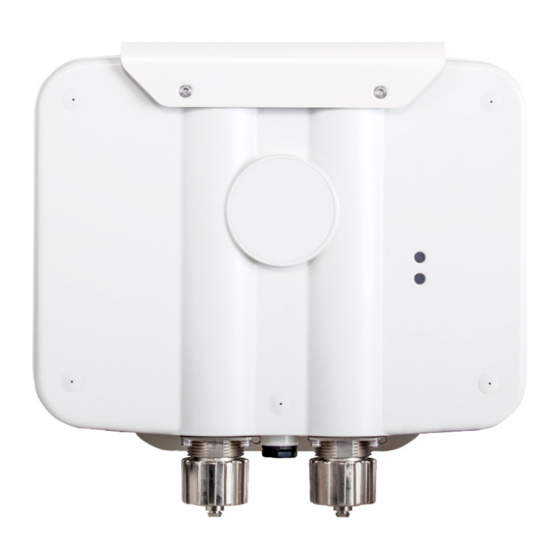
Page 20: Ap-6562 Led Indicators
AP-6562 Access Point 2.6 AP-6562 LED Indicators Both internal antenna and external antenna models have LED activity indicators on the front of the case. - Page 21 Installation Guide The LEDs provide a status display indicating error conditions, transmission, and network activity for the 5 GHz 802.11an (amber) radio or the 2.4 GHz 802.11bgn (green) radio. Task 5 GHz Activity LED (Amber) 2.4 GHz Activity LED (Green) Unadopted Blink interval at 5 times a second Normal...
-
Page 22: Basic Access Point Configuration
(AP-PSBIAS-7161-US or AP-PSBIAS-7161-WW) to supply power to the AP-6562 (once fully cabled). If your host system is a DHCP server, an IP address is automatically assigned to the Access Point and can be used for device connection. - Page 23 Installation Guide 5. Click the Login button to load the management interface. When logging in for the first time, you’re prompted to change the NOTE password to enhance device security in subsequent logins. If you get disconnected when running the wizard, you can connect again NOTE with the Access Point’s actual IP address (once obtained) and resume the wizard.
- Page 24 AP-6562 Access Point The Initial Setup Wizard displays the same content for each Access Point NOTE model supported. The only difference being the number of radios configurable by model. The Introduction screen displays the various actions that can be performed using the wizard under the Function Highlight field.
- Page 25 Installation Guide 7. Select Save/Commit within each page to save the updates made to that page's configuration. Select Next to proceed to the next page listed in the Navigation Panel without saving your updates. While you can navigate to any page in the navigation panel, you cannot NOTE complete the Initial AP Setup Wizard until each task in the Navigation Panel has a green checkmark.
- Page 26 AP-6562 Access Point • Standalone AP - Select this option to deploy this Access Point as an autonomous fat Access Point. A Standalone AP isn't managed by a Virtual Controller AP, or adopted by a controller If wanting to adopt the Access Point to a controller or service platform, NOTE use the controller or service platform’s resident UI to connect to the...
- Page 27 Installation Guide 13. The Typical Setup Wizard displays the Network Topology screen to define how the Access Point handles network traffic. 14. Select an Access Point Mode from the available options. • Router Mode -In Router Mode, the Access Point routes traffic between the local network (LAN) and the Internet or external network (WAN).
- Page 28 AP-6562 Access Point 15. Select Next. The Typical Setup Wizard displays the LAN Configuration screen to set the Access Point's LAN interface configuration. 16. Set the following DHCP and Static IP Address/Subnet information for the LAN interface: • Use DHCP - Select the checkbox to enable an automatic network address configuration using the Access Point’s DHCP server.
- Page 29 Installation Guide • DNS Forwarding - Select this option to allow a DNS server to translate domain names into IP addresses. If this option is not selected, a primary and secondary DNS resource must be specified. DNS forwarding is useful when a request for a domain name is made but the DNS server, responsible for converting the name into its corresponding IP address, cannot locate the matching IP address.
- Page 30 AP-6562 Access Point 19. Select Next. The Typical Setup Wizard displays the RADIUS Server Configuration screen if required. Otherwise, the Typical Setup Wizard displays the Summary and Commit screen. 20. Use the Radius Server Configuration screen to configure the users for the onboard RADIUS server. Use...
- Page 31 Installation Guide 21. Select Add User to display the dialog to enter user information to add to the RADIUS server user database. 22. Enter the following user information: • Username - Provide a user name used to authenticate the user. •...
- Page 32 AP-6562 Access Point 28. Select Next. The Typical Setup Wizard displays the Summary and Commit screen to summarize the screens (pages) and settings updated using the Typical Setup Wizard. No user intervention or additional settings are required. Its an additional means of validating the Access Point’s updated configuration before it’s deployed.
-
Page 33: Specifications
Power in (PoE) 802.3at 4.2 AP-6562 Internal Antenna Model Physical Specifications An AP-6562 internal antenna model access point has the following physical specifications: Dimensions 9.1 in W x 9.8 in H x 2.6 in D 23.1cm W x 24.9cm H x 24.9cm D... -
Page 34: Ap-6562 External Antenna Model Electrical Specifications
AP-6562 Access Point 4.4 AP-6562 External Antenna Model Power Specifications An AP-6562 external antenna model access point has the following power specifications: Operating voltage 36-57 VDC Power in (PoE) 802.3at 4.5 AP-6562 External Antenna Model Physical Specifications An AP-6562 external antenna model access point has the following physical specifications: Dimensions 9.1 in W x 9.8 in H x 2.6 in D... -
Page 35: Radio Specifications
Installation Guide 4.6 Radio Specifications AP-6562 model access points have the following radio specifications: Data rates supported 802.11b/g: 1,2,5.5,11,6,9,12,18,24,36,48, and 54Mbps 802.11a: 6,9,12,18,24,36,48, and 54Mbps 802.11n: MCS 0-15 up to 300Mbps Network standard 802.11a, 802.11b, 802.11g, 802.11n Wireless medium Direct Sequence Spread Spectrum (DSSS),... -
Page 36: Regulatory Information
AP-6562 Access Point Regulatory Information This guide applies to MODEL: AP-6562 All Zebra devices are designed to be compliant with rules and regulations in locations they are sold and will be labeled as required. Any changes or modifications to Zebra equipment, not expressly approved by Zebra, could void the user’s authority to operate the equipment. -
Page 37: Frequency Of Operation - Fcc And Ic
Installation Guide 5.2.2 Frequency of Operation – FCC and IC You are reminded of the need to observe restrictions on the radio devices in fuel depots, chemical plants etc. and areas where the air contains chemicals or particles (such as grain, dust, or metal powders). 5 GHz Only The use in the UNII (Unlicensed National Information Infrastructure) band 1 (5150-5250 MHz) is restricted to Indoor Use Only;... -
Page 38: Safety In Hospitals
AP-6562 Access Point 5.3.3 Safety in Hospitals Wireless devices transmit radio frequency energy and may affect medical electrical equipment. When installed adjacent to other equipment, it is advised to verify that the adjacent equipment is not adversely affected. Pacemakers Pacemaker manufacturers recommended that a minimum of 15cm (6 inches) be maintained between a handheld wireless device and a pacemaker to avoid potential interference with the pacemaker. -
Page 39: Us And Canada
Installation Guide 5.6 US and Canada Co-located statement To comply with FCC RF exposure compliance requirement, the antennas used for this transmitter must not be co-located or operating in conjunction with any other transmitter/antenna except those already approved in this filling. -
Page 40: Radio Frequency Interference Requirements - Canada
AP-6562 Access Point 5.9 Radio Frequency Interference Requirements – Canada This Class B digital apparatus complies with Canadian ICES-003. Cet appareil numérique de la classe B est conforme à la norme NMB-003 du Canada. This device complies with Industry Canada licence-exempt RSS standard(s) Rules. Operation is subject to the following two conditions: (1) this device may not cause harmful interference, and (2) this device must accept any interference received, including interference that may cause undesired operation. -
Page 41: Ce Marking Ad European Economic Area (Eea)
Installation Guide 5.10 CE Marking and European Economic Area (EEA) The use of 2.4GHz RLAN’s, for use through the EEA, have the following restrictions: • Maximum radiated transmit power of 100 mW EIRP in the frequency range 2.400 -2.4835 GHz. •... - Page 42 AP-6562 Access Point Restrict Frequency Range to: 2.450 – 2.4835 GHz. Taiwan 在 5.25-5.35 秭赫頻帶內操作之無線資訊傳輸設備,限於室內使用 Korea...
-
Page 43: Waste Electrical And Electronic Waste Equipment (Weee)
Installation Guide 5.14 Waste Electrical and Electronic Equipment (WEEE) English: For EU Customers: All products at the end of their life must be returned to Zebra for recycling. For information on how to return product, please go to: www.zebra.com/weee. Français: Clients de l'Union Européenne: Tous les produits en fin de cycle de vie doivent être retournés à Zebra pour recyclage. -
Page 44: Turkish Weee Statement Of Compliance
AP-6562 Access Point Malti: Għal klijenti fl-UE: il-prodotti kollha li jkunu waslu fl-aħħar tal-ħajja ta' l-użu tagħhom, iridu jiġu rritornati għand Zebra għar-riċiklaġġ. Għal aktar tagħrif dwar kif għandek tirritorna l-prodott, jekk jogħġbok żur: www.zebra.com/weee. Românesc: Pentru clienţii din UE: Toate produsele, la sfârşitul duratei lor de funcţionare, trebuie returnate la Zebra pentru reciclare. -
Page 45: Support
Installation Guide Support If you have a problem with your equipment, contact support for your region. Contact information is available at: www.zebra.com/support. When contacting support, please provide the following information: • Serial number of the unit • Model number or product name •... -
Page 46: Ap-6562 Access Point China Rohs Compliance
AP-6562 Access Point AP-6522 Series Access Point China ROHS Compliance 有害物质 铅 汞 镉 六价铬 多溴联 多溴二苯 (Pb) (Hg) (Cd) (Cr(VI)) 部件名称 苯 醚 (Parts) (PBB) (PBDE) 金属部件 (Metal Parts) 电路模块 (Circuit Modules) 电缆及电缆组件 (Cables and Cable Assemblies) 塑料和聚合物部件... - Page 47 Installation Guide...
- Page 48 Zebra Technologies Corporation Lincolnshire, IL 60069 USA Zebra and the Zebra head graphic are registered trademarks of ZIH Corp. The Symbol logo is a registered trademark of Symbol Technologies, Inc., a Zebra Technologies company. MN001370A01 Revision B April 2015...