
Related Manuals for Toro 38053


Summary of Contents for Toro 38053
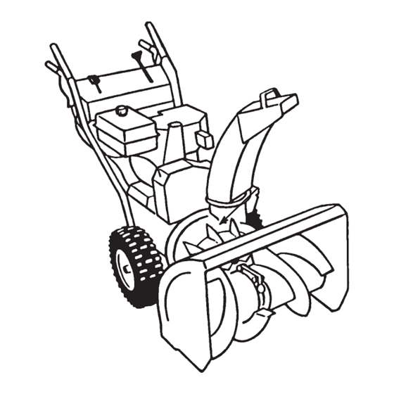
- Page 1 Form No. 3326-394 Rev B 824 Power Throw Snowthrower Model No. 38053—220000001 and Up Operator’s Manual International English (GB)
-
Page 2: Table Of Contents
Installing the Traction Rod ....Dealer or Toro Customer Service and have the model and Installing the Auger/Impeller Drive Control serial numbers of your product ready. Figure 1 illustrates Linkage . -
Page 3: Safety
The following instructions have been adapted from the ANSI/OPEI B71.3–1995 standard and the ISO 8437:1989 Operation standard. Information or terminology specific to Toro snowthrowers is enclosed in parenthesis. Do not put hands or feet near or under rotating parts. Keep clear of the discharge opening at all times. -
Page 4: Toro Snowthrower Safety
The following list contains safety information specific to building. Open the outside doors; exhaust fumes are Toro products or other safety information that you must dangerous. know. Do not clear snow across the face of slopes. Exercise Rotating auger/impeller can cut off or injure fingers or extreme caution when changing direction on slopes. -
Page 5: Sound Pressure Level
9.9 m/s , based on measurements of identical machines per To ensure the best performance and safety, purchase EN 1033. only genuine Toro replacement parts and accessories. Sound Pressure Level This unit has a sound pressure at the operator’s ear of 93 dB(A), based on measurements of identical machines per Directive 84/538/EEC. -
Page 6: Safety And Instruction Decals
Safety and Instruction Decals Safety decals and instructions are easily visible to the operator and are located near any area of potential danger. Replace any decal that is damaged or lost. 94-2568 94-2558 1. Cutting/dismemberment in impeller and auger hazard—keep bystanders away 1. - Page 7 Tecumseh Part No. 36501 1. Primer Tecumseh Part No. 35077 1. Key ignition 4. Fast 2. Engage to start the 5. Increasing scale engine 6. Slow 3. Disengage to stop the 7. Stop the engine engine Tecumseh Part No. 37119 1.
-
Page 8: Assembly
Assembly Note: Determine the left and right sides of the machine from the normal operating position. Loose Parts DESCRIPTION QTY. Handle assembly Bolts Installing the handle assembly Curved washers Speed selector rod Cotter pin Installing the speed selector rod Flat washer Spring Installing the traction rod Installing the traction rod... -
Page 9: Installing The Speed Selector Rod
3. Hold the handle assembly in the installation position and insert the upper traction rod through the loop in the lower traction rod (Fig. 4). Figure 5 1. Inner axle hole and wheel 2. Outer axle hole 3. Axle pin m-4039 Note: To use tire chains (optional), install the axle pins through the outer axle holes. -
Page 10: Installing The Traction Rod
m-2670 m-2628 Figure 7 Figure 9 1. Trunnion 2. Speed selector rod 1. Traction control lever 3. Three to 4 inches (7.6 to 10.2 centimeters) 2. Approximately 5 inches (12.7 centimeters) 4. Handgrip 4. Install the speed selector rod into the selector arm, add one flat washer on the rod, and secure it with a cotter pin (Fig. -
Page 11: Installing The Chute Control Rod
2. Install the lower link through the outer hole in the lower Installing the Chute Control control rod as shown in Figure 10. 3. Insert the upper control rod through the loop in the lower link (Fig. 10). 1. Assemble the chute control bracket and rod to the left side of the handle assembly with the bolt and the 4. -
Page 12: Before Starting
Before Starting 8. If the oil level is below the Add mark on the dipstick, slowly pour only enough oil into the filler hole to raise the oil level to the Full mark on the dipstick. Filling the Engine Crankcase Important Do not overfill the crankcase with oil and with Oil... -
Page 13: Checking The Tire Pressure
Use a fuel stabilizer/conditioner regularly during operation Danger and storage. A stabilizer/conditioner cleans the engine during operation and prevents gum-like varnish deposits from forming in the engine during periods of storage. In certain conditions, gasoline is extremely flammable and highly explosive. A fire or Important Do not use fuel additives other than a fuel explosion from gasoline can burn you and others... - Page 14 m–4034 Figure 16 1. Ignition switch 3. Throttle Figure 15 2. Choke 4. Primer 1. Auger/impeller drive 4. Discharge chute control control lever 5. Chute deflector handle Choke (Fig. 16)—Rotate the choke clockwise to the On 2. Traction control lever 6.
-
Page 15: Removing The Carburetor Heater Box
Removing the Carburetor Important Use the carburetor heater box as a reference for the choke and throttle positions. Heater Box If you operate the engine when the air temperature is above Installing the Carburetor 40 F (4 C), remove the carburetor heater box (Fig. 18). Heater Box To install the carburetor heater box, reverse steps 1 through 9 of Removing the Carburetor Heater Box on page 15. -
Page 16: Stopping The Engine
Note: If the engine does not start or if the air temperature is Snowthrowing Tips –10 F (–23 C) or colder, the engine may need additional priming. After pushing in the primer, try to start the engine before priming again. Danger 10. - Page 17 Do not overload the snowthrower by clearing snow at too fast a rate. If the engine slows down, shift the snowthrower into a lower gear to reduce the forward speed. In wet or slushy conditions, maintain maximum engine speed, and do not overload the engine to prevent clogging the discharge chute.
-
Page 18: Maintenance
Maintenance Note: Determine the left and right sides of the machine from the normal operating position. Recommended Maintenance Schedule Maintenance Service Maintenance Procedure Interval Check the engine oil level. Refer to Checking the Engine Oil Level on page 19. Check the auger gearbox grease and add grease if necessary. Refer to Checking the Auger Gearbox Grease on page 19. -
Page 19: Checking The Engine Oil Level
Caution If you leave the wire on the spark plug, someone could accidently start the engine and seriously injure you or other bystanders. Disconnect the wire from the spark plug before you do any maintenance. Set the wire aside so that it does not accidentally contact the spark plug. -
Page 20: Adjusting The Speed Selector
5. Loosen the 4 flange nuts that secure both skids to the 8. To adjust the scraper, loosen the 5 mounting screws auger side plates (Fig. 22) until the skids slide up and (Fig. 23), level the scraper, and tighten the mounting down easily. -
Page 21: Replacing The Traction Drive Belt
4. If the linkage is properly adjusted and the problem 5. Remove the idler pulley spring (Fig. 25). Let the brake persists, contact an Authorized Service Dealer. arm assembly hang free but out of the way. 5. Connect the wire to the spark plug. 6. -
Page 22: Adjusting The Auger/Impeller Drive Belt
m-2677 m-2678 Figure 27 Figure 29 1. Traction drive belt 4. Engine pulley sheave 2. Engine pulley 5. Auger/impeller drive belt 1. Tabs in holes 3. Indexing rib in indexing notch 19. Have someone squeeze the auger/impeller drive control lever (Fig. 15) against the handgrip, and install the belt 14. -
Page 23: Replacing The Auger/Impeller Drive Belt
7. Remove the engine crankshaft bolt, lock washer, and washer (Fig. 26). Danger 8. Separate and remove the engine pulley sheave (Fig. 26). Improperly adjusting the auger/impeller may 9. Remove the auger/impeller drive belt (Fig. 26). cause it to turn when disengaged. A rotating auger or impeller can cut off or injure fingers, hands, or 10. -
Page 24: Changing The Engine Oil
3. Drain the gasoline from the fuel tank; refer to Emptying the Fuel Tank on page 25. 4. Tip the snowthrower forward onto its auger housing and block it so that it cannot fall. 5. Remove the 8 bolts that hold the back and the bottom covers in place and remove the covers (Fig. -
Page 25: Replacing The Spark Plug
8. Wipe up any spilled oil. Danger 9. Connect the wire to the spark plug. Gasoline is highly flammable; it can ignite and Replacing the Spark Plug cause serious personal injury. Drain gasoline outdoors. Use a Champion RJ-19LM or equivalent spark plug. Install Drain gasoline from a cold engine only. -
Page 26: Preparing The Engine
3. Stop the engine, allow it to cool, and drain the fuel tank Light Kit or run the engine until it stops. Refer to Emptying the Fuel Tank on page 25. 4. Start the engine and run it until it stops. 5. -
Page 27: Troubleshooting
Troubleshooting Toro designed and built your snowthrower for trouble-free operation. Check the following components and items carefully, and refer to Maintenance on page 18 for more information. If a problem continues, see an Authorized Service Dealer. Problem Possible Causes Corrective Action Electric starter does not turn 1. - Page 28 Problem Possible Causes Corrective Action 3. The fuel tank is nearly empty or 3. Drain and fill the fuel tank with contains stale fuel. fresh gasoline (not more than 30 days old). If the problem persists, contact an Authorized Service Dealer. 4.