Haier AU182XFERA Installation Manual
X-multi inverter
Hide thumbs
Also See for AU182XFERA:
- Installation manual (18 pages) ,
- Service manual (79 pages) ,
- Service manual (143 pages)
Table of Contents
Advertisement
Available languages
Available languages
R410A
OUTDOOR UNIT
INVERTER
Please read this manual carefully before using this air conditioner
Please keep this manual safely for future use
X-MULTI INVERTER
EN
INSTALLATION MANUAL
IT
MANUALE DI INSTALLAZIONE
MANUEL D'INSTALLATION
FR
INSTALLATIONSANLEITUNG
DE
MANUAL DE INSTALACIÓN
ES
AU182XFERA
AU222XFERA
AU252XGERA
AU282XHERA
AU342XHERA
AU362XHERA
No. 0150501212 B
Advertisement
Chapters
Table of Contents

Related Manuals for Haier AU182XFERA


Summary of Contents for Haier AU182XFERA
- Page 1 X-MULTI INVERTER OUTDOOR UNIT INSTALLATION MANUAL INVERTER MANUALE DI INSTALLAZIONE MANUEL D’INSTALLATION INSTALLATIONSANLEITUNG MANUAL DE INSTALACIÓN AU182XFERA AU222XFERA AU252XGERA AU282XHERA AU342XHERA AU362XHERA Please read this manual carefully before using this air conditioner Please keep this manual safely for future use...
- Page 3 Haier Industrial Park, No.1 Haier Road, Qingdao, P.R.China CONFORMITÀ ALLE DIRETTIVE EUROPEE PER I MODELLI: AU182XFERA AU222XFERA AU252XGERA AU282XHERA AU342XHERA AU362XHERA SPECIFICHE DI SMALTIMENTO: Tutti i prodotti sono conformi alle seguenti normative europee: Il climatizzatore è contrassegnato con questo simbolo, - Direttiva 73/23/EEC Basso Voltaggio ciò...
- Page 4 Haier Industrial Park, No.1 Haier Road, Qingdao, P.R.China ÜBEREINSTIMMUNG MIT DEN EUROPÄISCHEN RICHTLINIEN FÜR DIE MODELLE: AU182XFERA AU222XFERA AU252XGERA AU282XHERA AU342XHERA AU362XHERA HINWEISE ZUR ENTSORGUNG: Alle Produkte erfüllen die folgenden europäischen Richtlinien: Das Klimagerät ist mit diesem Symbol gekennzeich- - Niederspannungsrichtlinie 73/23/EWG...
- Page 5 Haier Industrial Park, No.1 Haier Road, Qingdao, P.R.China Contains fluorinated greenhouse gases covered by the Kyoto Protocol R410A 1+2= INFORMAZIONI IMPORTANTI SUL REFRIGERANTE UTILIZZATO Questo prodotto contiene gas fluorurati ad effetto serra inclusi nel Protocollo L’etichetta compilata deve essere collocata in prossimità della portata di cari- di Kyoto.
- Page 6 Haier Industrial Park, No.1 Haier Road, Qingdao, P.R.China Contains fluorinated greenhouse gases covered by the Kyoto Protocol R410A 1+2= WICHTIGE INFORMATIONEN HINSICHTLICH DES VERWENDETEN KÄLTEMITTELS Dieses Produkt enthält fluorierte Treibhausgase, die durch das Kyoto-Proto- Das ausgefüllte Etikett muss in der Nähe der Kältemittel-Einfüllöffnung ange- koll abgedeckt werden.
-
Page 7: Outdoor Unit
R410A MULTI SPLIT SERIES ROOM AIR CONDITIONER OUTDOOR UNIT INSTALLATION MANUAL AU182XFERA AU222XFERA AU252XGERA AU282XHERA AU342XHERA AU362XHERA Please read this manual carefully before installing the units. Please keep this manual safely for future use. -
Page 8: Table Of Contents
Contents Unit appearance Cautions Safety precautions Installation instructions Installation drawings of indoor and outdoor units Matching of the indoor and outdoor units 8-13 Installation procedure 14-17 Purging method: to use vacuum pump Wiring work 19-22 Test running & Items to confirm Trouble shooting... -
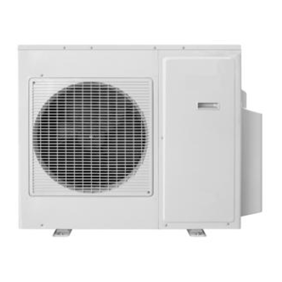
Page 9: Unit Appearance
Unit appearance AU182XFERA AU252XGERA AU222XFERA AU282XHERA AU362XHERA AU342XHERA... -
Page 10: Cautions
Cautions Consult your local authorities for the name and Disposal of the old air conditioner address of the waste materials collecting centers and Before disposing an old air conditioner that goes waste paper disposal services nearest to your house. out of use, please make sure it's inoperative and safe. - Page 11 Cautions 3. If the fuse on PC board is broken please change All electrical repairs must be carried out by it with the type of T 3.15A /250VAC or T qualified electricians. Inadequate repairs may result 25A/250VAC. in a major source of danger for the user of the air Please check the circuit diagram about the fuse conditoiner.
-
Page 12: Safety Precautions
Safety precautions To ensure proper installation, please read this safety precautions carefully before the installation. After installation, start the unit correctly and ensure that you show the customer how to operate and maintain the units. WARNING! Incorrect operations may result in severe consequences of death or serious injuries. CAUTION! Incorrect operations may result in injuries or machine damages;... -
Page 13: Installation Instructions
Place, where the distance of more than 1m from televisions, radios, wireless apparatuses and fluorescent lamps can be left. In the case of fixing the remote controller on a wall, place where the indoor unit can receive signals when the fluorescent lamps in the room are lightened. Installation dimensions(mm) AU182XFERA AU222XFERA 113.5 113.5... - Page 14 Installation instructions AU252XGERA AU282XHERA AU342XHERA 1068 AU362XHERA 1068...
-
Page 15: Installation Drawings Of Indoor And Outdoor Units
Installation drawings of indoor and outdoor units 1. Do not connected the embedded branch piping and the outdoor unit when only carrying out piping work without connecting the indoor unit in ordor to add another indoor unit later. Make sure no dirt or mositure gets into eigher side of the embedded branch piping. -
Page 16: Matching Of The Indoor And Outdoor Units
Matching of the indoor and outdoor units WARNING! Combinations those marked * can not be applied where the temperature in winter is too low and in summer is too higher to avoid bad heating or cooling effect. AU182XFERA Combination Remark AU222XFERA... - Page 17 Matching of the indoor and outdoor units AU252XGERA Remark Combination...
- Page 18 Matching of the indoor and outdoor units AU282XHERA Remark Combination...
- Page 19 Matching of the indoor and outdoor units AU342XHERA Remark Combination...
- Page 20 Matching of the indoor and outdoor units AU362XHERA Remark Combination...
- Page 21 Matching of the indoor and outdoor units Remark Combination...
-
Page 22: Installation Procedure
(The shorter the refrigerant piping, the better the performance. Connect so that the piping is as short as possible. Shortest allowable length per room is 3m) AU252XGERA AU282XHERA Outdoor unit capacity class AU182XFERA AU222XFERA AU342XHERA AU362XHERA Piping to each indoor unit 25m max. - Page 23 Installation procedure 3. Limitations values on the piping work . The piping length information, please refer the following table. Item Unit Descriptions Standard Maximum Size of the liquid side connection pipe A, B, C, D, E liquid pipe 6.35 A, B, C, D,E Gas pipe Size of the gas side connection pipe 9.52 Conneting pipe length...
- Page 24 Installation procedure Refrigerant piping work 1. Selection of pipe To this unit, both liquid and gas pipes shall be insulated as they become low temperature in operation. Use optional parts for piping set or pipes covered with equivalent insulation material. 6.35mm ( 1/4'' ) x 0.8mm Liquid pipe Gas pipe...
-
Page 25: Installation Procedure
Installation procedure 4.Cutting and Flaring work of piping Pipe cutting is carried out with a pipe cutter and burs must be removed. After inserting the flare nut, flaring work is carried out. Flare tooling die Size A (mm) Pipe diameter Liquid side 6.35mm(1/4") 0.8~1.5... -
Page 26: Purging Method: To Use Vacuum Pump
Purging method: to use vacuum pump Liquid stop valve .Detach the service portis cap of 3-way valve, the Gas stop valve 2 way valve valve rod's cap for 2-way valve and 3-way valves, connect 3 way valve the service port into the projection of charge hose (low) Gauge maifold(R410A) for gaugemanifold. -
Page 27: Wiring Work
Wiring work 1. Electric wiring Note: The air conditioner must use special circuit , and wiring by the qualified electrician according to the wiring rules specified in national standard. The grounding wire and the neutral wire shall be strictly separated. Connect the neutral wire with grounding wire is incorrect. - Page 28 Loosen wire cover , put the communication wire through the wire cover B, and connect them to terminal block correspondingly. After connection, fasten wire cover B to its previous state. Note: Power line and communication wire are provided by consumers themselves. AU182XFERA AU252XGERA Terminal blocks...
- Page 29 Wiring work 5. Example wiring diagram. (AU182XFERA AU222XFERA AU252XGERA) Indoor unit B Indoor unit A Indoor unit C 1(L) 2(N) C1 C2 (P Q) Outdoor unit 1PH, 220-230V~, 50Hz Power supply cable: H05RN-F 3G 4.0mm Communication cable (Shield wire): H05RN-F 2X1.5mm Connecting cable : H05RN-F 3G 2.5mm...
- Page 30 Wiring work 7. Example wiring diagram. (AU282XHERA AU342XHERA AU362XHERA) Indoor unit E Indoor unit D Indoor unit B Indoor unit C 1(L) 2(N) 1(L) 2(N) 1(L) 2(N) 1(L) 2(N) Indoor unit A 1(L) 2(N) Outdoor unit 1PH, 220-230V~, 50Hz Power supply cable: Communication cable (Shield wire): Connecting cable: H05RN-F 3G (5.0~8.0)mm...
-
Page 31: Test Running & Items To Confirm
Test running & Items to confirm Test running Before starting the test running, please confirm the following works have been done successfully. 1) Correct piping work; 2) Correct wiring work; 3) Correct match of indoor and outdoor unit; 4) Proper recharge of refrigerant if needed; 5) Correct indoor unit addresses setting. -
Page 32: Trouble Shooting
Trouble shooting FAILURE STATE OF TROUBLE POSSIBLE REASONS CODE LED 5-4-3-2-1 SHOOTING Faulty defrost sensor Te Sensor disconnected, or broken, or short circuit Faulty sensor Tao Sensor disconnected, or broken, or short circuit Faulty sensor Ts Sensor disconnected, or broken, or short circuit Faulty sensor Td Sensor disconnected, or broken, or short circuit Over current of the system, or broken of the current... - Page 35 CLIMATIZZATORE MULTISPLIT INVERTER R410A MANUALE DI INSTALLAZIONE UNITÀ ESTERNA AU182XFERA AU222XFERA AU252XGERA AU282XHERA AU342XHERA AU362XHERA • Si prega di leggere il presente manuale prima di installare il climatizzatore. • Conservare il presente manuale per ogni futura evenienza. IST HA053 Rev. 04-2007...
- Page 36 Indice Avvertenze Precauzioni di sicurezza Accessori per l'installazione Scelta del luogo di installazione Dimensioni Alimentazione Schema per l'installazione delle unità interna ed esterna Combinazioni ammesse tra unità interne e unità esterna Numerazione delle unità interne Limitazioni nell'installazione Carica aggiuntiva Tubazioni refrigerante Esecuzione del vuoto Collegamenti elettrici Test di funzionamento...
-
Page 37: Avvertenze
Avvertenze Norme di smaltimento del vecchio climatizzatore Prima di smaltire il vostro vecchio climatizzatore, accertatevi che sia spento e staccate la spina dalla presa di corrente. Il refrigerante con- tenuto all'interno richiede una speciale procedura per lo smaltimento. I materiali di valore contenuti nel climatizzatore possono essere rici- clati, informatevi presso il vostro Comune o la discarica della vostra città. -
Page 38: Precauzioni Di Sicurezza
Precauzioni di sicurezza Si prega di leggere le presenti “Precauzioni di Sicurezza” prima • Tutti i circuiti devono essere dotati di messa a terra. Accertar- di procedere all'attenta esecuzione del lavoro di installazione. si che la forza esterna del cavo non scarichi sulla morsettiera, Dopo l'installazione, spiegare al cliente il funzionamento e le nor- fissandolo adeguatamente. -
Page 39: Scelta Del Luogo Di Installazione
• Per un migliore comfort si consiglia l'installazione delle unità interne esattamente negli ambienti che si vogliono climatizzare e non in zone di accesso quali corridoi, anticamere, ecc. Dimensioni (mm) AU182XFERA - AU222XFERA AU252XGERA AU282XHERA - AU342XHERA - AU362XHERA 1068... -
Page 40: Schema Per L'installazione Delle Unità Interna Ed Esterna
Schema per l'installazione delle unità interna ed esterna 1. Se si installa un'unità interna che verrà collegata in un secondo momento, non aprire i rubinetti del gas della macchina esterna in corrispondenza di tale unità. 2. Non è possibile collegare solamente una unità interna, bisogna collegare almeno due unità interne. Predisposizione per l'uscita tubazioni nell’UI posteriore sinistra... -
Page 41: Combinazioni Ammesse Tra Unità Interne E Unità Esterna
Combinazioni ammesse tra unità interne e unità esterna AU182XFERA AU222XFERA Note Note 2 unità interne 7000 12000 2 unità interne 7000 14000 9000 9000 9000 12000 9000 12000 9000 14000 12000 12000 12000 12000 3 unità interne 7000 7000 7000 3 unità... - Page 42 AU342XHERA AU362XHERA Note Note 2 unità interne 12000 18000 2 unità interne 12000 18000 14000 14000 14000 14000 14000 18000 14000 18000 18000 18000 18000 18000 3 unità interne 7000 7000 14000 3 unità interne 7000 7000 14000 7000 7000 18000 7000 7000...
-
Page 43: Numerazione Delle Unità Interne
Numerazione delle unità interne (modelli parete) Le unità interne devono essere numerate. Ogni unità deve corrispondere alla propria coppia di tubi, usare come riferimento il seguente schema: L'unità interna numerata 1 deve corrispondere al circuito frigorifero A L'unità interna numerata 2 deve corrispondere al circuito frigorifero B L'unità... - Page 44 Numerazione delle unità interne (modelli cassette) Le unità interne devono essere numerate. Ogni unità deve corrispondere alla propria coppia di tubi, usare come riferimento il seguente schema: L'unità interna numerata 1 deve corrispondere al circuito frigorifero A L'unità interna numerata 2 deve corrispondere al circuito frigorifero B L'unità...
- Page 45 ATTENZIONE: la procedura con gli interruttori esclude quel- Per verificare l'effettivo numero assegnato all'unità interna la con il telecomando. procedere come segue: • Tenere premuto il tasto di emergenza (sul pannello spie CON GLI INTERRUTTORI DIP SW01 E SW03 luminose dell'unità interna) fino a quando verranno emes- Gli interruttori DIP SW01 e SW03 si trovano sulla scheda si 5 beep consecutivi.
- Page 46 Numerazione delle unità interne (modelli canalizzati) ATTENZIONE: questo tipo di unità interna può impostare la CON GLI INTERRUTTORI DIP SW01 E SW03 numerazione solo con gli interruttori DIP. Gli interruttori DIP SW01 e SW03 si trovano sulla scheda elet- tronica dell'unità interna. Le unità...
- Page 47 Numerazione delle unità interne (modelli soffitto-pavimento) Le unità interne devono essere numerate. Ogni unità deve corrispondere alla propria coppia di tubi, usare come riferimento il seguente schema: L'unità interna numerata 1 deve corrispondere al circuito frigorifero A L'unità interna numerata 2 deve corrispondere al circuito frigorifero B L'unità...
- Page 48 ATTENZIONE: la procedura con gli interruttori esclude quel- Per verificare l'effettivo numero assegnato all'unità interna la con il telecomando. procedere come segue: • Tenere premuto il tasto di emergenza (sul pannello spie CON GLI INTERRUTTORI DIP SW01 E SW03 luminose dell'unità interna) fino a quando verranno emes- Gli interruttori DIP SW01 e SW03 si trovano sulla scheda si 5 beep consecutivi.
- Page 49 Numerazione delle unità interne (modelli console) Le unità interne devono essere numerate. Ogni unità deve corrispondere alla propria coppia di tubi, usare come riferimento il seguente schema: L'unità interna numerata 1 deve corrispondere al circuito frigorifero A L'unità interna numerata 2 deve corrispondere al circuito frigorifero B L'unità...
- Page 50 ATTENZIONE: la procedura con gli interruttori esclude quel- Per verificare l'effettivo numero assegnato all'unità interna la con il telecomando. procedere come segue: • Tenere premuto il tasto di emergenza (sul pannello spie CON GLI INTERRUTTORI DIP SW01 E SW02 luminose dell'unità interna) fino a quando verranno emes- Gli interruttori DIP SW01 e SW02 si trovano sulla scheda si 5 beep consecutivi.
-
Page 51: Limitazioni Nell'installazione
Più corte sono le tubazioni refrigerante, migliori sono le prestazioni del climatizzatore. La lunghezza minima per ogni unità interna è 3m. Lunghezza massima AU182XFERA AU222XFERA AU252XGERA AU282XHERA AU342XHERA AU362XHERA tubazioni per ogni unità interna totale del tubo liquido di tutte le unità... - Page 52 AU252XGERA AU282XHERA AU342XHERA Unità Descrizione Standard Max. A, B, C, D tubo liquido Diametro del tubo lato liquido Ø 6,35 A, B, C, D tubo gas Diametro del tubo lato gas Ø 9,52 L1 (solo andata) Lunghezza tubazioni per singola unità interna ≤10 ≤25 L2 (solo andata)
- Page 53 AU362XHERA Unità Descrizione Standard Max. A, B, C, D, E tubo liquido mm Diametro del tubo lato liquido Ø 6,35 A, B, C, D, E tubo gas Diametro del tubo lato gas Ø 9,52 L1 (solo andata) Lunghezza tubazioni per singola unità interna ≤10 ≤25 L2 (solo andata)
-
Page 54: Carica Aggiuntiva
è necessario aggiungere 0,020kg/m per ogni metro di linea in più. Esempio AU182XFERA: Se la lunghezza totale dell'impianto è 45m (la lunghezza viene calcolata solo per il tubo del liquido) la carica aggiuntiva sarà: lunghezza totale - precarica = 45m - 30m = 15m 15m x 0,020kg = 0,300kg di R410A... -
Page 55: Esecuzione Del Vuoto
4. Metodo per il taglio e la flangiatura dei tubi Quando il tubo è troppo lungo o l'estremità è danneggiata, bisogna tagliare o flangiare il tubo. Tagliare il tubo con un tagliatubi e rimuovere le sbavature. Quindi inserire il dado e flangiare il tubo. Diametro tubazione Misura A Lato liquido... - Page 56 2 vie e il tappo della valvola 3 vie un po' oltre il punto in cui il momento tor- cente aumenta improvvisamente. valvola 3 vie tappo per valvola tappo per valvola tappo per apertura di servizio AU182XFERA - AU222XFERA AU252XGERA - AU282XHERA - AU342XHERA AU362XHERA Ø 6,35mm (1/4”) all’unità valvola 2 vie all’unità...
-
Page 57: Collegamenti Elettrici
Collegamenti elettrici 1. Avvertenze • Il sistema di climatizzazione necessita di un circuito dedicato, e i collegamenti elettrici devono essere effettuati da personale specia- lizzato, in conformità alle normative e agli standard in vigore nel paese di installazione. • Il filo di messa a terra e il filo neutro devono essere assolutamente separati. •... - Page 58 • Per configurare e controllare i collegamenti far riferimento al manuale d'installazione dell'unità interna. • Collegamenti errati possono causare anomalie al sistema. • La distanza tra i cavi di segnale e i cavi di alimentazione deve essere di almeno 50mm. 5. Schema elettrico AU182XFERA - AU222XFERA unità interna C unità interna B unità...
- Page 59 6. Schema elettrico AU252XGERA unità interna D unità interna C unità interna B unità interna A Cavo di alimentazione: H05RN-F 3G (4,0~5,0)mm Cavo di segnale (cavo schermato): H05RN-F 2x1,5mm Cavo di alimentazione UI: H05RN-F 3G 2,5mm 1PH, 220-230V~, 50Hz 7. Schema elettrico AU282XHERA - AU342XHERA unità...
- Page 60 8. Schema elettrico AU362XHERA unità interna E unità interna D unità interna C unità interna B unità interna A unità esterna 1PH, 220-230V~, 50Hz Cavo di alimentazione: H05RN-F 3G (5,0~8,0)mm Cavo di segnale (cavo schermato): H05RN-F 2x1,5mm Cavo di alimentazione UI: H05RN-F 3G 2,5mm 9.
-
Page 61: Test Di Funzionamento
Test di funzionamento • Prima di iniziare il test di funzionamento, confermare la corret- • Lo split dovrà darvi conferma di aver ricevuto il segnale attra- ta esecuzione dei seguenti lavori: verso un segnale acustico di 5 beep. collegamento tubazioni refrigerante, collegamenti elettrici, •... -
Page 62: Diagnostica Unità Esterna
Diagnostica unità esterna Rimuovere la protezione rubinetti, i LED si trovano vicino alla morsettiera della comunicazione. G " significa LED acceso, il simbolo " G Il simbolo " " significa LED spento. Cod. Tipo di anomalia Possibile causa dell'anomalia errore 5-4-3-2-1 Sensore temp. -
Page 63: Diagnostica Unità Interna
Diagnostica unità interna (modelli parete) Codice di errore sul pannello UI Tipo di anomalia Possibile causa dell'anomalia Sonda temp. ambiente Tai difettosa Sensore scollegato, o difettoso, o in corto circuito Sonda temp. Tc1 difettosa Sensore scollegato, o difettoso, o in corto circuito Sonda temp. - Page 64 Diagnostica unità interna (modelli canalizzati) Codice di errore sul comando a filo Tipo di anomalia Possibile causa dell'anomalia Sonda temp. ambiente Tai difettosa Sensore scollegato, o difettoso, o in corto circuito Sonda temp. Tc1 difettosa Sensore scollegato, o difettoso, o in corto circuito Sonda temp.
- Page 65 Diagnostica unità interna (modelli console) Numero lampeggi led TIMER Tipo di anomalia Possibile causa dell'anomalia Sonda temp. ambiente Tai difettosa Sensore scollegato, o difettoso, o in corto circuito Sonda temp. Tc1 difettosa Sensore scollegato, o difettoso, o in corto circuito Sonda temp.