Kenwood DMC-J7R Service Manual
Hide thumbs
Also See for DMC-J7R:
- Instruction manual (46 pages) ,
- Instruction manual (46 pages) ,
- Instruction manual (46 pages)
Table of Contents
Advertisement
Quick Links
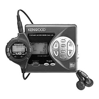
PORTABLE MD RECORDER
DMC-J7R
SERVICE MANUAL
Transparency cover *
(B10-)
Knob
(K27-2272-08)
Front cabinet
(A02-2808-08)
MD cover
(F07-1638-08)
S: Silver, B: Blue
General
Power source
........................
DC
DC 5 V (AC adaptor)
AC 230 V, 50 Hz
DC 3 V Separately available battery case
DC 4.0 V : Separately available car
Power consumption
.............
7 W (AC adaptor)
Output power
........................
RMS; 20 mW (10 mW + 10 mW)
(0.2 % T.H.D.)
Charging time
.......................
Approx. 3.0 hours
(When using the AC adaptor included
with the unit)
Battery life
When using the recharge-
When using two,
able battery NB-L10A (fully
commercially available,
charged) included with the
high capacity, "AA" size,
unit
alkaline batteries (in the
separately available battery
case)
Continuous recording:
Continuous recording:
Approx. 4 hours
Approx. 4.5 hours
Continuous play:
Continuous play:
Approx. 8 hours
Approx. 6.5 hours
Note:
The battery case is only sold in certain areas. For more details,
please ask your dealer.
The continuous recording time is for analogue input when the
volume level is set to "VOL 0".
The continuous play time shows the value when the volume level is
set to "VOL 15".
The above values are the standard values when the unit is charged
and used at an ambient temperature of 20
The operating time when using alkaline batteries may be different,
depending on the type and manufacturer of the batteries, and on
the operating temperature.
In compliance with Federal Regulations, following are reproduc-
tions of labels on, or inside the product relating to laser product
safety.
SPECIFICATIONS
3.6 V (rechargeable lithium-ion
battery NB-L10A x 1)
(commercially available, "AA"
size, alkaline battery x 2)
adaptor, DC-C70
(for cars with a 12-24 V DC
negative earth electrical system)
When using two, commercially
available, high capacity, "AA"
size batteries with the
rechargeable battery (fully
charged)
Continuous recording:
Approx. 8.5 hours
Continuous play:
Approx. 14.5 hours
o
C.
© 1998-6/B51-5441-00 (K/K) 3163
* Refer to parts list on page 26.
Input sensitivity
.....
Recording level
Reference input level
MI C H
MIC L
LINE
Output level
...........
Specified output
Headphones
—
LINE
300mV (-12dB)
Dimensions
...........................
Width: 87.0 mm (3-7/16")
Height: 29.4 mm (1-3/16")
Depth: 81.5 mm (3-7/32")
Weight
...................................
219 g (0.49 lbs.) with rechargeable
battery
..........................
Input socket
Line/optical digital, microphone
(powered by the main unit)
Output socket
.......................
Headphones (impedance: 32
ohms)/remote control unit
MiniDisc Recorder
Type
.......................................
Portable MiniDisc recorder
Signal readout
......................
Non-contact, 3-beam semi-coductor
laser pick-up
....................
Audio channels
Stereo 2 channels/monaural (long-
play mode) 1 channel
............
Frequency response
20 - 20,000 Hz (± 3 dB)
.....................
Rotation speed
Approx 400 - 900 rpm
Error correction
ACIRC (Advanced Cross Interleave
....................
Reed-Solomon Code)
Coding
...................................
ATRAC (Adaptive Transform
Acoustic Coding), 24-bit computed type
Recording method
...............
Magnetic modulation overwrite method
............
Sampling frequency
44.1 kHz (32 kHz and 48 kHz
signals are converted to 44.1 kHz,
and then recorded.)
Unmeasurable (less than ±0.001% W.peek)
Wow and flutter
....................
KENWOOD-Crop. certifies this equipment conforms to DHHS
Regulations No. 21 DFR 1040. 10, Chapter 1, Subchapter J.
DANGER : Laser radiation when open and interlock defeated.
AVOID DIRECT EXPOSURE TO BEAM
Upper case assy
(A02-2814-08) : S
(A02-2862-08) : B
Knob base
(A02-2816-08)
Knob
(K29-2270-08)
Bottom cabinet *
(A02-)
Input impedance
0.25 mV
10 k ohms
2.5 mV
10 k ohms
100 mV
20 k ohms
Load
Maximum
output level
impedance
10 mW +
32 ohms
10 mW
—
50 k ohms
Advertisement
Table of Contents

Related Manuals for Kenwood DMC-J7R


Summary of Contents for Kenwood DMC-J7R
-
Page 1: Specifications
....depending on the type and manufacturer of the batteries, and on the operating temperature. KENWOOD-Crop. certifies this equipment conforms to DHHS In compliance with Federal Regulations, following are reproduc- Regulations No. 21 DFR 1040. 10, Chapter 1, Subchapter J. -
Page 2: Table Of Contents
AC adaptor from the 1. Unplug the AC adaptor from the AC AC socket immediately and contact an au- socket. thorized KENWOOD service centre. 2. Remove the battery. 3. Leave the unit completely unpowered for approximately 30 seconds. -
Page 3: Controls
DMC-J7R CONTROLS 7 Notes about the rechargeable battery NAMES OF CONTROLS AND INDICATORS ÷ A rechargeable lithium-ion battery is Since the rechargeable battery is Remote Control Unit the only kind that can be used. vulnerable to damage, please note Even if the battery supplied with the the following. -
Page 4: Disassembly For Repair
DMC-J7R DISASSEMBLY FOR REPAIR Caution on Disassembly (A1)x2 Ø1.4x2mm Follow the below-mentioned notes when disassembling the unit and reassembling it, to keep it safe and ensure Pull (A1)x1 excellent performance: Ø1.4x2mm 1. Take the battery and minidisc out of the unit. - Page 5 DMC-J7R DISASSEMBLY FOR REPAIR Remove the mechanism according to the disassembling meth- (A2)x3 ods 1 to 3. (See Page 8.) ø1.4x2.8mm How to remove the spindle motor (See Fig. 9-1.) 1. Remove the solder joint (A1) x 1 of flex PWB.
- Page 6 J701 OPTICAL INPUT UNIT (LB1638) IC651 DC IN MOTOR DIGITAL INPUT LIFT +2.5 DRIVER MOTOR VCC VS D-RAM +2.5 (IC202) J701 LINE INPUT (74ACT02) HEAD J702 DRIVER HEAD MIC IN (IR3R54N) IC701 AUDIO AMP. RIPPLE Q721 +2.5 VCC VEE IC351 FILTER +4.5 +2.8V...
- Page 7 IC401 RH-iX2680AF03(IX2680AF):System Microcomputer Port Name Terminal Name Input/Output Function Pin No. Port Name Terminal Name Input/Output Function Pin No. RCLAT Output Record audio P120 SWP UP Output Asterisk input Output for pull-up PBOPON Output Audio IC output stage control output 2*~7* P121~P126 P121~P126...
-
Page 8: Trouble Shooting
It is advisable to use the TEST mode (refer to Error Data Display Mode, P15) indicating the causes of troubles before • Abnormal display starting repair. Causes of operation errors (up to 10 errors) are recorded as error codes. This information is useful for repair. - Page 9 Test disc • The spindle motor fails to run.Does the head move MD adjustment needs two types of disc, namely recording disc (low reflection disc) and playback-only disc (high reflection disc). Check the IC201 periphery. Type Test disc Does the waveform appear on the IC201 pins 24 and 25 after TEST mode AUTO2 completion and in this state? High reflection disc TG YS-1 (SONY) Low reflection disc...
- Page 10 Operation in each TEST mode 1. AUTO1 Mode 6. Error data display Mode • When the STOP button is pressed while the AUTO1 menu appears or during automatic adjustment, the mode changes to the TEST mode • Reversing when SKIP DOWN button is pressed stop state.
- Page 11 Test Mode Change Chart Preautomatic Adjustment Tset Mode Menu A U T O 1 : Preautomatic Adjustment menu PLAY T E S T : Test Mode STOP SKIP UP SKIP DOWN A T 1 : During preadjustment adjustment Slide external Slide internal Adjustment error periphery move...
- Page 12 Continuous Playback ATT Autoadjustment • Continuous playback from current pickup position P L A Y : Continuous playback menu A U T O 2 : ATT Autoadjustment menu PLAY PLAY S Q # # # # : Continuous playback (pit section) : Continuous playback (groove section) A P # # # # A T 2...
- Page 13 Continuous Record Error History Display • Error history clear • Continuous record from the current pickup position D A T A R E C : Error history display menu : Continuous record menu PLAY PLAY : Continuous record C L E A R A P # # # # : Error history clear # # # #: Address...
-
Page 14: Note On Schematic Diagram
DMC-J7R NOTES ON SCHEMATIC DIAGRAM (CH), (TH), (RH), (UJ): Temperature compensation • Resistor: (ML): Mylar type To differentiate the units of resistors, such symbol as K and • The indicated voltage in each section is the one measured M are used: the symbol K means 1000 ohm and the symbol... -
Page 15: Parts Descriptions
DMC-J7R PARTS DESCRIPTIONS... -
Page 16: Waveforms Of Md Circuit
DMC-J7R WAVEFORMS OF MD CIRCUIT Stopped Stopped 1994 / 12 / 16 00:24:17 Stopped 1994 / 12 / 16 01:03:40 1994 / 12 / 15 22:54:19 CH1=1mV CH2=500mV CH3=5V CH4=2V 50ms/div CH1=2V CH2=2V CH3=2V CH4=2V 50us/div CH1=1V CH2=2V CH3=500mV 2ms/div... - Page 17 DC IN J801 D800 BATTERY TERMINAL (+) R817 10 11 BATTERY TERMINAL (-) R818 C603 C874 C354 C353 Q352 R807 C805 L801 R808 C604 L600 R809 C808 C804 IC804 R801 C351 C806 R802 L603 L604 C803 D802 Q802 R805 R803 C823 R821 R829...
- Page 18 EXT. BATTERY TERMINAL C802 (220) TP801 MAIN PWB-A1 (BOTTOM) L887 TP805 P20 7-R TP806 TP803 FROM LCD 15 14 FLEXIBLE PWB P20 5-S P20 3-S Q801 FROM KEY FROM MECHA TP809 FLEXIBLE PWB (231) IC805 FLEXIBLE PWB (8) TP808 C903 TP662 TP666 C878...
-
Page 19: Pc Board
PC BOARD(Component side view) M901 M902 PICKUP UNIT (PU) SPINDLE MOTOR SLED MOTOR M903 LIFT MOTOR SW901 DISC IN CN601 SW902 TO MAIN PWB DISC PROTECT P18 4-H MECHA FLEXIBLE PWB UNIT (8) CN101 TO MAIN PWB P18 5-I MAGNETIC HEAD FLEXIBLE PWB (23) MAGNETIC HEAD (32) -
Page 20: Schematic Diagram
DTC144EE 2SJ305 MAIN PWB-A1 TP451 VOL UP TP452 VOL DOWN TP453 SKIP DOWN C112 DADATA 0.033 R455 R456 R457 TP454 SKIP UP ADDATA 5.6K 8.2K R458 HKEY2 TP455 ENTER C111 DFCK 0.0033 TP456 EDIT R203 BCLK TP457 DISPLY TP139 C109 C107 LRCK TP458... - Page 21 DMC-J7R Voltage value IC101 IC201 IC202 IC401 IC402 IC501 IC601 IC651 NO. VOLTAGE NO. VOLTAGE NO. VOLTAGE NO. VOLTAGE NO. VOLTAGE NO. VOLTAGE NO. VOLTAGE NO. VOLTAGE NO. VOLTAGE NO. VOLTAGE 0.7V 1.0V 1.5V 2.5V 0.95V 2.5V 2.5V 0.7V 2.5V 1.7V...
-
Page 22: Exploded View
DMC-J7R EXPLODED VIEW (MECHANISM) PH-901 (SW902) (SW901) 12x2 M901 M902 M903 31x2 Parts with exploded view numbers larger than 700 are not supplied. - Page 23 DMC-J7R EXPLODED VIEW (UNIT) J703 OPTICAL /LINE IN J701 MIC IN J702 PWB-A2 PWB-A1 CHAR- ACTER DISP AUTO MARK SYNC /F.PLAY RECO- RDING BASS MODE /DELETE /INSERT DMC-J7R Parts with exploded view numbers larger than 700 are not supplied.
- Page 24 Desti- Ref. No Parts No. Description Ref. No Parts No. Description ress Parts nation marks ress Parts nation marks DMC-J7R W01-0941-05 HEADPHONE W01-0948-05 HEADPHONE TEE1M W01-0955-08 CARRYING CASE A02-2808-08 FRONT CABINET W03-5946-08 RECHARGEABLE BATTERY A02-2864-08 BOTTOM CABINET ,SILVER W08-0669-08 AC ADAPTER...
- Page 25 New Parts New Parts Parts without Parts No. are not supplied. Parts without Parts No. are not supplied. Les articles non mentionnes dans le Parts No. ne sont pas fournis. Les articles non mentionnes dans le Parts No. ne sont pas fournis. Teile ohne Parts No.
- Page 26 New Parts New Parts Parts without Parts No. are not supplied. Parts without Parts No. are not supplied. Les articles non mentionnes dans le Parts No. ne sont pas fournis. Les articles non mentionnes dans le Parts No. ne sont pas fournis. Teile ohne Parts No.
- Page 27 New Parts New Parts Parts without Parts No. are not supplied. Parts without Parts No. are not supplied. Les articles non mentionnes dans le Parts No. ne sont pas fournis. Les articles non mentionnes dans le Parts No. ne sont pas fournis. Teile ohne Parts No.
-
Page 28: Parts List
P.O.Box 61318, Jebel Ali, Dubai, U.A.E. KENWOOD ELECTRONICS U.K. LIMITED KENWOOD ELECTRONICS SINGAPORE PTE LTD. KENWOOD House, Dwight Road, Watford, Herts., WD1 8EB., United Kingdom No. 1 Genting Lane #02-02, KENWOOD Building, Singapore, 349544 KENWOOD ELECTRONICS BELGUM N.V. KENWOOD ELECTRONICS (MALAYSIA) SDN BHD.