Panasonic FV-05-11VKS1 Installation Insrtuctions
Hide thumbs
Also See for FV-05-11VKS1:
- Installation instructions manual (12 pages) ,
- Service manual (10 pages)
Table of Contents
Advertisement
Quick Links
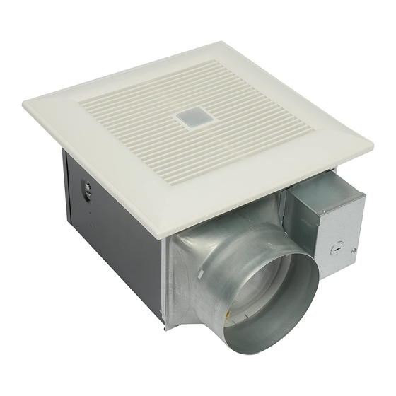
FV-05-11VKS1
Thank you for purchasing this Panasonic product.
FV-05-11VK1
Model No.
Contents
GENERAL SAFETY INFORMATION
INDICATION (PLUG 'N PLAY FUNCTION DEVICES)
MAINTENANCE (CLEANING)
PRODUCT SERVICE
FV-11-15VK1
BACK COVER
BACK COVER
BACK COVER
2-3
4
4
4
5
5
5
6
6-7
7
8
8-10
10
11
Advertisement
Table of Contents

Related Manuals for Panasonic FV-05-11VKS1


Summary of Contents for Panasonic FV-05-11VKS1
-
Page 1: Table Of Contents
MOTION (PLUG ‘N PLAY FUNCTION DEVICES) INSTALLATION (PLUG ‘N PLAY FUNCTION DEVICES) INSTALLATION (NEW CONSTRUCTION) 8-10 INSTALLATION (RETROFIT) MAINTENANCE (CLEANING) PRACTICAL GUIDE TO INSTALLATION BACK COVER SPECIFICATIONS BACK COVER PRODUCT SERVICE BACK COVER FV-11-15VK1 Thank you for purchasing this Panasonic product. -
Page 2: For Your Safety
For Your Safety To reduce the risk of injury, loss of life, electric shock, fire, malfunction, and damage to equipment or property, always observe the following safety precautions. Explanation of symbol word panels The following symbol word panels are used to classify and describe the level of hazard, injury, and property damage caused when the denotation is disregarded and improper use is performed. - Page 3 WARNING Canada only: Not to be installed in a ceiling thermally insulated to a value greater than R40. Do not disassemble the unit for reconstruction. It may cause fire or electric shock. When this product is no longer being operated, please remove the product to prevent the possibility of falling.
-
Page 4: Please Read Prior To Installing This Fan
Multi-Speed module, these models kick up to a maximum level of 150 CFM for the FV-11-15VK1 and 110 CFM for the FV-05-11VKS1 and FV-05-11VK1 either when the switch is turned on or activated by the optional Condensation Sensor module or the optional Motion Sensor module. -
Page 5: Supplied Accessories
Pick-A-Flow switch (FV-MSVK1 not included) Junction box Fan body Adaptor Damper Multi-Speed module Flex-Z Fast bracket (FV-05-11VKS1 only, 3 7/8 (100) 10 1/4 (260) 3 7/8 (100) other models not included) WIRING DIAGRAM Fan body Junction box Switch for power (114°C Fuse) -
Page 6: Feature
The Pick-A-Flow switch on the face of all WhisperGreen Select fans allows the option to choose 50 – 80 – 110 CFM for the FV-05-11VK1, FV-05-11VKS1 or 110 – 130 – 150 CFM for the FV-11-15VK1. These fans can run continuously or intermittently, depending upon the needs of the owner. -
Page 7: Motion (Plug 'N Play Function Devices)
INDICATION (PLUG ‘N PLAY FUNCTION DEVICES) CONTINUED PLUG ‘N PLAY Modular Component Accessories Sold Separately, Not Included With Base Model Fan FV-CSVK1 Condensation Sensor module turns the base fan on or boosts to higher speed when humidity is detected when used in combination with the FV-VS15VK1. -
Page 8: Installation (Plug 'N Play Function Devices)
You can purchase the specified Plug ‘N Play devices that are explained on page 6-7 and install them in positions . Position can only be used with Multi-Speed module (model FV-05-11VKS1 already have this control installed), position can be used for any of the other optional control modules. - Page 9 INSTALLATION (NEW CONSTRUCTION) CONTINUED 7. Refer to wiring diagram on page 5. FV-05-11VKS1 Conduit Follow all the local electrical safety codes as well Earth ground FV-05-11VK1 FV-11-15VK1 to green as the National Electrical Code (NEC). Using UL approved wire nuts, connect house Wire nut power wires to ventilating fan wires.
-
Page 10: Installation (Retrofit)
INSTALLATION (NEW CONSTRUCTION) CONTINUED 13. Adjust Pick-A-Flow switch; if used, adjust the FV-VS15VK1 Multi-Speed module. (Fig.10) Ceiling Refer to indication on page 6. Grille 14. Insert the other mounting spring into the slot as shown and mount grille to fan body. (Fig.11) CAUTION Fig.10 Mount grille carefully so that lead wire is... - Page 11 WARNING Mounting spring Disconnect power source before working Grille on unit. Slot Gloves Fig.15 CAUTION Routine maintenance must be done every year. Please wear gloves during Clasp the cleaning work. Ceiling Never use gasoline, benzene, thinner or any other such chemicals for cleaning the ventilating fan.
-
Page 12: Practical Guide To Installation
Warning Concerning Removal of Covers. The unit should be serviced by qualified technicians only. Your product is designed and manufactured to ensure a minimum of maintenance. Should your unit require service or parts, call Panasonic Call Center at 1-866-292-7299 (USA) or 1-800-669-5165 (Canada). Two Riverfront Plaza, Newark, NJ 07102...