Kenwood DPX502 Service Manual
Hide thumbs
Also See for DPX502:
- Training manual (52 pages) ,
- Firmware update manual (1 page) ,
- Instruction manual (40 pages)
Table of Contents
Advertisement
Quick Links
CD/USB RECEIVER
DPX502
DPX502U/DPX502UY
DPX-MP5100U
SERVICE MANUAL
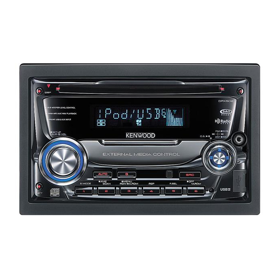
Panel assy
DPX502 (A64-4096-02)
SUB WOOFER LEVEL CONTROL
WMA MP3 AAC WAV PLAYBACK
FRONT USB & AUX INPUT
EXTERNAL MEDIA CONTROL
Panel assy
DPX-MP5100U (A64-4097-02)
SUB WOOFER LEVEL CONTROL
WMA MP3 AAC WAV PLAYBACK
FRONT USB & AUX INPUT
EXTERNAL MEDIA CONTROL
* Adhesive double-coated tape
(H30-0595-04)
* Escutcheon
(B07-3172-12)
DPX502
PTY/C.S.
USB
Remote controller assy (RC-547)
(A70-2085-05)
DPX-MP5100U
USB
Compact disc
* Screw set
(W01-1704-05)
(N99-1779-05)
* Escutcheon assy
(B07-3046-04)
This product complies with the
© 2007-7 PRINTED IN JA PAN
B53-0556-00 ( N ) 521
Panel assy
DPX502U/DPX502UY (A64-4098-02)
SUB WOOFER LEVEL CONTROL
WMA MP3 AAC WAV PLAYBACK
FRONT USB & AUX INPUT
EXTERNAL MEDIA CONTROL
Battery
(Not supplied)
* DC cord
(E30-6428-05)
* Mounting hardware assy
(J22-0429-13)
* Escutcheon
(B07-3165-02)
This product uses Lead Free solder.
RoHS
DPX502U
s
PTY
USB
* DC cord
(E30-6671-05)
* Lever
(D10-4589-04) x2
directive for the European market.
Advertisement
Table of Contents

Related Manuals for Kenwood DPX502


Summary of Contents for Kenwood DPX502
- Page 1 DPX502U/DPX502UY DPX-MP5100U SERVICE MANUAL © 2007-7 PRINTED IN JA PAN B53-0556-00 ( N ) 521 Panel assy Panel assy DPX502 (A64-4096-02) DPX502U/DPX502UY (A64-4098-02) DPX502 DPX502U SUB WOOFER LEVEL CONTROL SUB WOOFER LEVEL CONTROL WMA MP3 AAC WAV PLAYBACK WMA MP3 AAC WAV PLAYBACK FRONT USB &...
- Page 2 ELECTRIC UNIT (X34- ) DME1 SERVO MECHA Q601,606 Q600,602,605,607 PRE OUT D3.3V IC705 IC703 IC300 J600 (FRONT) SW MUTE MUTE PRE OUT AUX (ISO IN) (REAR/SW) IC711 CH(ISO IN) IC400 IC716 FM/AM D1.8V POWER E-VOL SP OUT(FL) IC700 IC704 SP OUT(FR) WIN IN SP OUT(RL) OFFSET...
-
Page 3: Block Diagram
DPX502/502U/502UY DPX-MP5100U BLOCK DIAGRAM CD PLAYER UNIT (X32-598x-xx) MOTHER BOARD (X34- ) DPU1 MRST D.GND MSTOP MSTOP A,B,C,E,F LEVEL SHIFT DATA LEVEL SHIFT DATA 1 CHIP IC RF AMP LEVEL SHIFT MUTE SERVO MUTE PROCESSOR (0-00),(0-01) ONLY L-ch MICRO R-ch... -
Page 4: Components Description
DPX502/502U/502UY DPX-MP5100U COMPONENTS DESCRIPTION ● ELECTRIC UNIT (X34-560x-xx) Ref. No. Application / Function Operation / Condition / Compatibility SW Regulator Outputs 5.0V. Power supply for D5V, FL+B and USB5V A8V REF Power Supply Outputs 1.27V IC100 Reset IC Lo when detection voltage goes below 3.6V... - Page 5 DPX502/502U/502UY DPX-MP5100U COMPONENTS DESCRIPTION Ref. No. Application / Function Operation / Condition / Compatibility Q601,606 Pre-out Mute Driver When a base goes Lo, mute driver is turned on Q600,602,605,607 Pre-out Mute SW When a base goes Hi, pre-out is muted...
-
Page 6: Microcomputer's Terminal Description
DPX502/502U/502UY DPX-MP5100U MICROCOMPUTER’S TERMINAL DESCRIPTION ● SYSTEM µ-COM: IC102 on X34- (ELECTRIC UNIT) Truth Pin No. Pin Name Application Processing / Operation / Description Value Table External display remote control input REMO and panel remote control input LX REQ M... - Page 7 DPX502/502U/502UY DPX-MP5100U MICROCOMPUTER’S TERMINAL DESCRIPTION Truth Pin No. Pin Name Application Processing / Operation / Description Value Table Not used Output L fi xed CD DISC12 SW 12cm-disc detection CD LOS SW CD loading detection CD MUTE CD mute request...
- Page 8 DPX502/502U/502UY DPX-MP5100U MICROCOMPUTER’S TERMINAL DESCRIPTION Truth Pin No. Pin Name Application Processing / Operation / Description Value Table LINE MUTE Line mute detection TEL mute: Below 1V, NAVI mute: Over 2.5V PWIC DC DET DC offset detection IC2 SDA I/O I2C data input/output...
-
Page 9: Test Mode
DPX502/502U/502UY DPX-MP5100U TEST MODE ● How to enter the test mode • “TNCON_NG” : Cannot communicate with the front-end. Press and hold the [1] and [3] keys and reset. ● RDS/RBDS automatic measurement (While “– – – –” is being displayed, power can be ON for 30 minutes.) - Page 10 DPX502/502U/502UY DPX-MP5100U TEST MODE ● AUDIO adjust mode ● MENU • Press the [AUD] key and enter the audio adjustment • Press [Q] key briefl y to enter the MENU. mode. • Press the remote control [DNPP/SBF] key and the •...
- Page 11 DPX502/502U/502UY DPX-MP5100U TEST MODE Key pressed briefl y: Number of CD EJECT times is CD time code error count data display (missing counts) ↓ displayed. [switched by [ ] / [ ] keys] (Display) CNT_LOSE ↔ CDDA_ _xx ↔ CDROM_xx ↔...
- Page 12 DPX502/502U/502UY DPX-MP5100U TEST MODE ● Clearing backup/installer memory, CD mecha- Abnormal ending 2 : CD mechanism information/Service infor mation/DC offset error detection infor mation nism information, service information and DC initialization : NG offset error detection information (E2PROM data clearing)
- Page 13 “PROTECT” is not shown. 6. Release the test mode. (Refer to “How to clear the test mode”.) ● FM/AM channel space switching (DPX502/DPX- * Note: All clear cannot be used to clear the security code. MP5100U only) While power is OFF, press and hold [1] and [5] keys, and •...
-
Page 14: Dc Offset Error
DPX502/502U/502UY DPX-MP5100U DC OFFSET ERROR ● Purpose • Key specifi cation Prevent customer’s vehicle speakers damages, burnouts, • Other keys than eject and power keys are invalid. and smoking. Avoid the connected speakers to be bur ned out, • Display specifi cation damaged, or to smoke when DC occurs between the •... -
Page 15: Installer Memory Specifications
DPX502/502U/502UY DPX-MP5100U INSTALLER MEMORY SPECIFICATIONS At specialists (or specialty stores), when the installer sends • The contents read out by the call key shall be refl ected the vehicle back to the user, they may make the store- only to the current source at the time→EQ curve is “USER”... - Page 16 DPX502/502U/502UY DPX-MP5100U PC BOARD (COMPONENT SIDE VIEW) ELECTRIC UNIT X34-560x-xx (J76-0369-42) IC400 J601 D409 J600 C422 R404 13 11 12 8 C400 R412 R401 C423 R402 C406 C405 C402 C424 C601 C602 C605 C606 R602 R603 R608 R609 R622 R620...
- Page 17 DPX502/502U/502UY DPX-MP5100U X34-560x-xx Ref. No. Address C423 I G O C424 IC102 IC103 IC200 IC300 IC400 IC700 IC702 IC703 IC704 CN201 TP200 IC705 IC708 IC709 D219 IC710 C801 L200 C902 IC711 CP730 C206 IC714 IC715 IC716 C700 C732 IC700 C726...
- Page 18 DPX502/502U/502UY DPX-MP5100U PC BOARD (FOIL SIDE VIEW) ELECTRIC UNIT X34-560x-xx (J76-0369-42) C921 C914 W405 C912 R911 C412 C925 C413 R916 R305 R309 R317 R313 R301 C114 R148 C805 R145 C109 R143 R134 R135 C108 R133 C107 R132 R165 R151 IC100...
- Page 19 DPX502/502U/502UY DPX-MP5100U SYNTHESIZER UNIT X15-1050-10 (J76-0441-02) Q603 Q602 C905 R616 R612 X34-560x-xx R503 Ref. No. Address IC100 IC101 IC101 IC500 IC712 R141 R136 IC100 R115 W501 C500 R116 R511 Q500 R502 Q501 IC500 Q600 Q601 R510 C512 R512 Q602 R509...
- Page 20 DPX502/502U/502UY DPX-MP5100U PC BOARD (COMPONENT SIDE VIEW) SWITCH UNIT X16-614x-xx (J76-0442-02) X16-614x-xx Ref. No. Address Refer to the schematic diagram for the values of resistors and capacitors.
- Page 21 DPX502/502U/502UY DPX-MP5100U PC BOARD (FOIL SIDE VIEW) SWITCH UNIT X16-614x-xx (J76-0442-02) SW VFL PAN5V FL+B X16-614x-xx Ref. No. Address VFD INH VFD PAN VFD CE VFD CL VFD SYS DT REMO ENC CCW ILL+B Refer to the schematic diagram for the values of resistors and capacitors.
- Page 22 DPX502/502U/502UY DPX-MP5100U PC BOARD (COMPONENT SIDE VIEW) CD PLAYER UNIT X32-5980-02 (J76-0377-02) R28 R27 X32-5980-02 Ref. No. Address Refer to the schematic diagram for the values of resistors and capacitors.
- Page 23 DPX502/502U/502UY DPX-MP5100U PC BOARD (FOIL SIDE VIEW) CD PLAYER UNIT X32-5980-02 (J76-0377-02) P-ON2 P-ON1 IOP+ R105 R101 R100 FCS+ R103 FCS- A3.3V NPWDOWN R129 R128 C15 R13 TP24 CP11 R132 OCDSEL R102 TESTIN0 /MRST /MUTE FCLK /MSTOP LO/EJ MOTOR BU5V...
- Page 24 DPX502/502U/502UY DPX-MP5100U PRE OUT X16- FRONT REAR AUX IN ELECTRIC UNIT (X34-560x-xx) J600 CN601 TP28 ANT. C505 A500 C904 C905 TP43 TP41 TP44 0.01 0.01 0.01 C504 AM+B TP29 RFGND Q500 0.01 FMANT C605 C606 C615 AMANT Q501 R508 R503...
- Page 25 DPX502/502U/502UY DPX-MP5100U CD-CH J601 C115 IC103 0.01 5.0V uCOM5V MUTING LOGIC IC R635 C103 C620 0.01 0.01 D616 IC101 D619 D615 5.0V R152 D620 TP59 D614 5.0V 100K D621 D611 D613 D612 TP60 E2PROM R911 10 S SOC REQ PWIC MUTE...
- Page 26 DPX502/502U/502UY DPX-MP5100U uCOM5V C110 0.01 R155 3.9K R154 3.9K SW5V SW5V 0 or 1.6 or 2.5 or 3.4 SURGE or 5.0V CP104 100 ACC DET CD MOTOR CD LOEJ R147 CD LOE LIM SW 2.2K R148 4.7K R144 2.2K CD DISC8 SW...
- Page 27 DPX502/502U/502UY DPX-MP5100U F1 (10A) to DC CORD TP116 (F52-0023-05) QUAD 2-INPUT AND GATE FUSE C751 IC712 3.3V R769 0.01 3.3V IC709 100K TP114 5.0V 5.0V 3.3V 3.3V 3.3V R782 M-RST TP115 C941 68P CONVE 3.3V R783 3300u16 3.3V 3.3V C930 0.1...
- Page 28 DPX502/502U/502UY DPX-MP5100U 3.3V 3.3V 1.8V 1.8V 1.8V M-RST CONVERTER Q706 Q704 3.3V 3.3V 3.3V 3.3V VSSIO 3.3V 3.3V 3.3V L700 R744 560 T MCKI 3.3V R718 47K TP700 R745 3.3V 3.3V 3.3V T SDTI R719 47K R736 22K R824 3.3V...
- Page 29 BYTE 3.3V facturer’s rec om mend ed parts 3.3V (refer to parts list). Indicates safety critical com- DPX502/502U/502UY, DPX-MP5100U (1/2) po nents. To reduce the risk of SIGNAL LINE electric shock, leakage-cur rent GND LINE B LINE : S2V60-5009F46 or re sis tance mea sure ments 1.8V...
- Page 30 DPX502/502U/502UY DPX-MP5100U (3G-1G) (1G) (1G) SWITCH UNIT (X16-614x-xx) col3 col1 col2 CP6 47K Q1-3 GRID RESTART DRIVER TP16 ILL DET PAN5V RTRY FL+B ILL+B TP22 X34- RESET J200 TRIANGLE TP19 VFD INH VFD PAN DATA AUTO TP20 VFD CE TP10...
- Page 31 (ex posed parts are ac cept ably in su lat ed from the supply cir cuit) be fore the ap pli ance is DPX502/502U/502UY, DPX-MP5100U (2/2) returned to the customer. • DC voltages are as measured with a high im- pedance volt me ter.
- Page 32 DPX502/502U/502UY DPX-MP5100U CD PLAYER UNIT (X32-598x-xx) A3.3V 3.3V A8V SW D.GND A3.3V A.GND 1.5V Q1 SW ASEL OCDSEL 5V-3.3V LEVEL SHIFT BCLK 3.3V LRCK 3.3V 0-3.3V SRDATA 0-3.2V 3.3V R106 MUTE R MUTE L N.C. CORRECTION SRVMON1 SRVMON1 (NOT USED)
- Page 33 DPX502/502U/502UY DPX-MP5100U A3.3V A.GND C71 10 C72 0.1 CAUTION : For continued safety, C73 10 16.934MHz re place safe ty critical com po nents C74 0.1 A GND2 only with manufacturer’s rec om - 2.60pp mend ed parts (refer to parts list).
- Page 34 DPX502/502U/502UY DPX-MP5100U EXPLODED VIEW (CD MECHANISM) DPU1 DFPC1 (X32) φ : N09-4460-15 M1.6x6.0 : N09-6317-05 M1.7x2.5 : N09-6004-15 M2x2 : N09-6007-15 φ 2x5(BLK) : N09-6051-15 1.6 WASHER : N19-2163-04 M2x2 : N39-2020-48 φ 2x3.5 : N09-6108-15 φ : N09-6155-15 Parts with the exploded numbers larger than 700 are not supplied.
-
Page 35: Exploded View (Unit)
DPX502/502U/502UY DPX-MP5100U EXPLODED VIEW (UNIT) Size AA battery (Not supplied) DME1 (X34) N83-3005-48 N83-3008-48 3x20 N83-3020-48 3x10 N80-3010-48 2.6x8 N82-2608-48 N84-3005-43 (X34) (X34) A500 (X15) (X34) (X34-) (X15) (X15) Depends on the models. Refer to the parts list. Parts with the exploded numbers larger than 700 are not supplied. -
Page 36: Exploded View (Panel)
DPX502/502U/502UY DPX-MP5100U EXPLODED VIEW (PANEL) 2.6x6 N78-2660-48 N80-2006-48 N80-2008-48 (X16) (X16) (X16-) 723 can not be removed from the panel. Parts with the exploded numbers larger than 700 are not supplied. -
Page 37: Parts List
N99-1779-05 SCREW SET K1M1 N78-2660-48 PAN HEAD TAPTITE SCREW S70-0106-05 TACT SWITCH K1 : DPX502 M1 : DPX-MP5100U E1 : DPX502U E2 : DPX502UY Indicates safety critical com po nents. (E : Europe K : North America M : Other Areas... - Page 38 J 1/16W UM6K1N DUAL FET RK74GA1J101J CHIP-COM 100 J 1/16W 2SB1295-E TRANSISTOR K1 : DPX502 M1 : DPX-MP5100U E1 : DPX502U E2 : DPX502UY Indicates safety critical com po nents. (E : Europe K : North America M : Other Areas...
- Page 39 C90-5620-05 ELECTRO 0.47UF 50WV C764-768 CK73GB1H103K CHIP C 0.010UF K K1 : DPX502 M1 : DPX-MP5100U E1 : DPX502U E2 : DPX502UY Indicates safety critical com po nents. (E : Europe K : North America M : Other Areas W : Without Europe)
- Page 40 CHIP-COM 100 J 1/16W R123,124 RK73GB2A104J CHIP R 100K J 1/10W K1 : DPX502 M1 : DPX-MP5100U E1 : DPX502U E2 : DPX502UY Indicates safety critical com po nents. (E : Europe K : North America M : Other Areas...
- Page 41 CHIP R 4.7K J 1/10W R745 RK73GB2A100J CHIP R J 1/10W K1 : DPX502 M1 : DPX-MP5100U E1 : DPX502U E2 : DPX502UY Indicates safety critical com po nents. (E : Europe K : North America M : Other Areas...
- Page 42 2SB1565 TRANSISTOR R92-1252-05 CHIP R 0 OHM J 1/16W E1E2 2SC4081 TRANSISTOR K1 : DPX502 M1 : DPX-MP5100U E1 : DPX502U E2 : DPX502UY Indicates safety critical com po nents. (E : Europe K : North America M : Other Areas...
- Page 43 D13-2151-04 GEAR D13-2152-04 GEAR D13-2153-04 GEAR D13-2154-04 GEAR K1 : DPX502 M1 : DPX-MP5100U E1 : DPX502U E2 : DPX502UY Indicates safety critical com po nents. (E : Europe K : North America M : Other Areas W : Without Europe)
-
Page 44: Specifications
Current consumption ..............10A Installation Size (W × H × D) LW tuner section : DPX502U/DPX502UY DPX502 ..182 × 112 × 160mm (7-3/16 × 4-7/16 × 6-5/16 inch) Frequency range .............153~281kHz DPX502U/DPX502UY ........182 × 112 × 160mm Usable sensitivity (S/N=20dB) ........... 45µV DPX-MP5100U ..........178 ×...