Advertisement
Quick Links
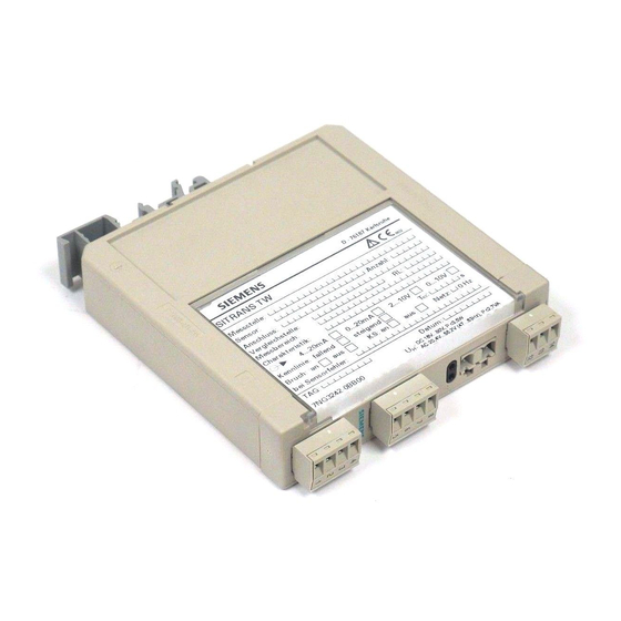
SITRANS T measuring instruments for temperature
Transmitters for rail mounting
SITRANS TW
four-wire system, universal, HART
Overview
3
The user-friendly transmitters for the control room
The SITRANS TW universal transmitter is a further development
of the service-proven SITRANS T for the 4-wire system in a
mounting rail housing. With numerous new functions it sets new
standards for temperature transmitters.
With its diagnostics and simulation functions the SITRANS TW
provides the necessary insight during commissioning and oper-
ation. And using its HART interface the SITRANS TW can be
conveniently adapted with SIMATIC PDM to every measurement
task.
All SITRANS TW control room devices are available in a non-
intrinsically safe version as well as in an intrinsically safe version
for use with the most stringent requirements.
Application
The SITRANS TW transmitter is a four-wire rail-mounted device
with a universal input circuit for connection to the following sen-
sors and signal sources:
• Resistance thermometers
• Thermocouple elements
• Resistance-based sensors/potentiometers
• mV sensors
• As special version:
- V sources
- Current sources
The 4-wire rail-mounted SITRANS TW transmitter wire is de-
signed for control room installation. It must not be mounted in
potentially explosive atmospheres.
All SITRANS TW control room devices are available in a non-
intrinsically safe version as well as in an intrinsically safe version
for use with the most stringent requirements.
Function
Features
• Transmitter in four-wire system with HART interface
• Housing can be mounted on 35 mm rail or 32 mm G rail
• Screw plug connector
• All circuits electrically isolated
• Output signal: 0/4 to 20 mA or 0/2 to 10 V
• Power supplies: 115/230 V AC/DC or 24 V AC/DC
• Explosion protection [EEx ia] or [EEx ib] for measurements
with sensors in the hazardous area
• Temperature-linear characteristic for all temperature sensors
3/38
Siemens FI 01 · 2010
© Siemens AG 2009
• Temperature-linear characteristic can be selected for all tem-
perature sensors
• Automatic correction of zero and span
• Monitoring of sensor and cable for open-circuit and short-cir-
cuit
• Sensor fault and/or limit can be output via an optional sensor
fault/limit monitor
• Hardware write protection for HART communication
• Diagnostic functions
• Slave pointer functions
Mode of operation
TC
RTD
8
4
A
µC
D
2
1
EEPROM
3
The signal output by a resistance-based sensor (two-wire, three-
wire, four-wire system), voltage source, current source or ther-
mocouple is converted by the analog-to-digital converter
(1, function diagram) into a digital signal. This is evaluated in the
microcontroller (2), corrected according to the sensor character-
istic, and converted by the digital-to-analog converter (6) into an
output current (0/4 to 20 mA) or output voltage (0/2 to 10 V). The
sensor characteristics as well as the electronics data and the
data for the transmitter parameters are stored in the non-volatile
memory (3).
AC or DC voltages can be used as the power supply (13). Any
terminal connections are possible for the power supply as a re-
sult of the bridge rectifier in the power supply unit. The PE con-
ductor is required for safety reasons.
A HART modem or a HART communicator permit parameteriza-
tion of the transmitter using a protocol according to the HART
specification. The transmitter can be directly parameterized at
the point of measurement via the HART output terminals (10).
The operation indicator (4) identifies a fault-free or faulty operat-
ing state of the transmitter. The limit monitor (9) enables the sig-
naling of sensor faults and/or limit violations. In the case of a cur-
rent output, the current can be checked on a meter connected
to test socket (12).
Diagnosis and simulation functions
The SITRANS TW comes with extensive diagnosis and simula-
tion functions.
Physical values can be defined with the simulation function. It is
thus possible to check the complete signal path from the sensor
input to Inside the control system without additional equipment.
The slave pointer functions are used to record the minimum and
maximum of the plant's process variable.
9
10
HART modem/
D
communicator
5
Output
11
U or I
A
12
Current test
6
A
0/4 ... 20 mA
Power
13
sup-
U
ply
H
unit
7
Advertisement

Related Manuals for Siemens SITRANS TW


Summary of Contents for Siemens SITRANS TW
- Page 1 With its diagnostics and simulation functions the SITRANS TW unit provides the necessary insight during commissioning and oper- ation. And using its HART interface the SITRANS TW can be conveniently adapted with SIMATIC PDM to every measurement task. All SITRANS TW control room devices are available in a non-...
- Page 2 Possible system configurations Type of connection • Normal connection The SITRANS TW transmitter as a four-wire rail-mounted device • Sum or parallel connection can be used in a number of system configurations: as a stand- • Mean-value or differential alone version or as part of a complex system environment, e.g.
- Page 3 Not possible • Lower and upper limit • Window (combination of lower and upper limits) • Limit and sensor fault detection can be combined • Hysteresis Parameterizable between 0 and 100 % of measuring range 3/40 Siemens FI 01 · 2010...
- Page 4 Intrinsic safety to EN 50 020 • for 7NG3242-xAxxx II (1) G D [EEx ia/ib ] IIB • for 7NG3242-xBxxx II (1) G D [EEx ia/ib ] IIC EC-Type Examination Certificate TÜV (German Technical Inspec- torate) 01 ATEX 1675 Siemens FI 01 · 2010 3/41...
- Page 5 µA 0 ... 750 -12 ... +100 µA 0.05 0 ... 1500 -120 ... +1000 µA 0 ... 3000 -1.2 ... +10 mA 0 ... 6000 -12 ... +100 mA -120 ... +1000 mA 3/42 Siemens FI 01 · 2010...
- Page 6 -1.2 V ... +10 V - Measuring range 0 ... 5 V - Source-proportional characteristic - Filter time 10 s - Output 0 ... 20 mA, line filter 60 Hz - No monitoring for sensor fault Siemens FI 01 · 2010 3/43...
- Page 7 German, English, • without French, Spanish, Italian, Portuguese and • for inputs [EEx ia] or [EEx ib] SIPROM T parameterization software Power supply Instruction Manual for SITRANS TW • 115/230 V AC/DC • German/English A5E00054075 • 24 V AC/DC • French/Italian/Spanish...
- Page 8 This range does not apply to mean-value and difference circuits. The max. permissible currents and voltages according to conformity cer- tificate must be observed in devices with explosion protection. Without detection of line breakage Siemens FI 01 · 2010 3/45...
- Page 9 Software filter to smooth the result Filter to suppress line disturbances on the measured signal. If signalling relay present for special appliciations Operating data: see „Special operating data“ 3/46 Siemens FI 01 · 2010...
- Page 10 J=on; N=off (standard: J) Type of relay output: A=open-circuit opera- tion; R=closed-circuit operation (standard: R) Switching delay T of relay output in s Range of values: 0.0 to 10.0 (standard: 0.0) Siemens FI 01 · 2010 3/47...
- Page 11 Single channel Channel 1 Differential connection 1 Channel 1 - Channel 2 Differential connection 2 Channel 2 - Channel 1 ½ ⋅ (Channel 1 + Channel 2) Mean-value 1 3/48 Siemens FI 01 · 2010...
- Page 12 10 and 11 • Device switched on and no error 10 and 11 • Device switched on and error 9 and 11 Dimensional drawings Dimensions for control room mounting, rail mounting in mm (inches) Siemens FI 01 · 2010 3/49...