D-Link DGS-3427 User Manual
Gigabit managed switch
Hide thumbs
Also See for DGS-3427:
- Product manual (424 pages) ,
- Specifications (5 pages) ,
- Reference manual (629 pages)

Related Manuals for D-Link DGS-3427


Summary of Contents for D-Link DGS-3427
-
Page 1: User Manual
User Manual DGS-3400 Series Product Model: Layer 2 Gigabit Managed Switch Release 1 ©Copyright 2005. All rights reserved. - Page 2 Microsoft Corporation. Other trademarks and trade names may be used in this document to refer to either the entities claiming the marks and names or their products. D-Link Computer Corporation disclaims any proprietary interest in trademarks and trade names other than its own.
-
Page 3: Table Of Contents
Table of Contents Intended Readers ................................viii Typographical Conventions................................viii Notes, Notices, and Cautions............................viii Safety Instructions................................ix Safety Cautions....................................ix General Precautions for Rack-Mountable Products ........................... x Protecting Against Electrostatic Discharge............................xi Introduction ............................1 Switch Description ..................................1 Features......................................2 Ports........................................ - Page 4 Introduction ..................................26 Logging in to the Web Manager ..............................27 Web-based User Interface................................28 Areas of the User Interface................................. 28 Web Pages ....................................... 29 Configuring the Switch ........................30 Device Information..................................30 IP Address ....................................... 33 Setting the Switch's IP Address using the Console Interface...................... 34 Port Configuration ...................................
- Page 5 IP-MAC Binding Blocked ................................67 Single IP Management (SIM) Overview ...........................68 SIM Using the Web Interface ..............................70 Topology......................................71 Tool Tips ....................................73 Menu Bar....................................77 Single IP Management Firmware Upgrade............................78 Single IP Management Configuration File Backup/Restore ....................... 79 Single IP Management Log Files ...............................
- Page 6 STP Instance Settings ..................................106 STP Port Settings................................... 107 Forwarding & Filtering ..............................109 Unicast Forwarding .................................. 109 Static Multicast Forwarding ..............................109 Multicast Filtering Mode ................................110 QoS....................................112 The Advantages of QoS................................. 112 Understanding QoS..................................113 Bandwidth Control..................................114 QoS Scheduling Mechanism................................115 QoS Output Scheduling .................................
- Page 7 SSH Algorithm ..................................166 SSH User Authentication Mode..............................168 Save, Reset and Reboot........................169 Save Changes ..................................169 Reset ....................................170 Reboot System.................................170 Logout .....................................170 Monitoring ............................171 Device Status.................................... 172 Module Information.................................. 172 CPU Utilization ..................................173 Port Utilization ..................................174 Packets Statistics....................................
-
Page 8: Intended Readers
xStack DGS-3400 Series Fast Ethernet Switch Intended Readers The xStack DGS-3400 series Manual contains information for setup and management of the Switch. This manual is intended for network managers familiar with network management concepts and terminology. Typographical Conventions Convention Description In a command line, square brackets indicate an optional entry. -
Page 9: Safety Instructions
xStack DGS-3400 Series Fast Ethernet Switch Safety Instructions Use the following safety guidelines to ensure your own personal safety and to help protect your system from potential damage. Throughout this safety section, the caution icon ( ) is used to indicate cautions and precautions that need to be reviewed and followed. -
Page 10: General Precautions For Rack-Mountable Products
xStack DGS-3400 Series Fast Ethernet Switch • To help prevent electric shock, plug the system and peripheral power cables into properly grounded electrical outlets. These cables are equipped with three-prong plugs to help ensure proper grounding. Do not use adapter plugs or remove the grounding prong from a cable. -
Page 11: Protecting Against Electrostatic Discharge
xStack DGS-3400 Series Fast Ethernet Switch • Do not overload the AC supply branch circuit that provides power to the rack. The total rack load should not exceed 80 percent of the branch circuit rating. • Ensure that proper airflow is provided to components in the rack. •... -
Page 12: Introduction
This manual describes the installation, maintenance and configurations concerning members of the xStack DGS-3400 Switch Series. These switches include: the DGS-3426, DGS-3427 and the DGS-3450. The DGS-3400 Series switches are similar in configurations and basic hardware and consequentially, most of the information in this manual will be universal to the whole xStack DGS-3400 Series. -
Page 13: Features
xStack DGS-3400 Series Fast Ethernet Switch Features The list of features below highlights the significant freatures of the xStack DGS-3400 Series. • IEEE 802.3z compliant • IEEE 802.3x Flow Control in full-duplex compliant • IEEE 802.3u compliant • IEEE 802.3ab compliant •... -
Page 14: Ports
One RS-232 DB-9 console port • One RS-232 DB-9 console port • One RS-232 DB-9 console port NOTE: For customers interested in D-View, D-Link Corporation's proprietary SNMP management software, go to the D-Link Website and download the software and manual. -
Page 15: Front-Panel Components
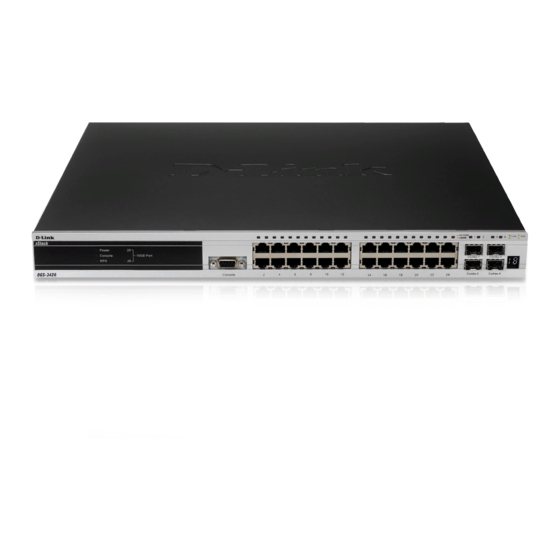
* Note that Stacking in the DGS-3400 Series is not yet supported in this firmware release. DGS-3426 Figure 2- 1. Front Panel View of the DGS-3426 as shipped DGS-3427 Figure 2- 2. Front Panel View of the DGS-3427 as shipped DGS-3450 Figure 2- 3. Front Panel View of the DGS-3450 as shipped... -
Page 16: Led Indicators
The Switch supports LED indicators for Power, Console, RPS and Port LEDs including 10GE port LEDs for optional module inserts.. Figure 2- 4. LED Indicators on DGS-3450 Figure 2- 5. LED Indicators on DGS-3427 Figure 2- 6. LED Indicators on DGS-3426... -
Page 17: Port Leds
xStack DGS-3400 Series Fast Ethernet Switch Description This LED will light green after powering the Switch on to indicate the ready state Power of the device. The indicator is dark when the Switch is no longer receiving power (i.e powered off). This LED will blink green during the Power-On Self Test (POST). -
Page 18: Rear Panel Description
Figure 2- 7. Rear panel view of DGS-3426 DGS-3427 The rear panel of the DGS-3427 contains an AC power connector, a redundant power supply connector and three empty slots for optional module inserts. Figure 2- 8. Rear panel view of DGS-3427... -
Page 19: Side Panel Description
Switch for proper ventilation. Be reminded that without proper heat dissipation and air circulation, system components might overheat, which could lead to system failure and severely damage components. Figure 2- 10. Side Panels (DGS-3450) Figure 2- 11. Side Panels (DGS-3426 and DGS-3427) -
Page 20: Installation
7. One CD Kit for D-View 5.1 Standard version(for Europe only) 8. Registration card & China Warranty Card (for China only) If any item is missing or damaged, please contact your local D-Link Reseller for replacement. Installation Guidelines Please follow these guidelines for setting up the Switch: •... -
Page 21: Installing The Switch Without The Rack
xStack DGS-3400 Series Fast Ethernet Switch Installing the Switch without the Rack First, attach the rubber feet included with the Switch if installing on a desktop or shelf. Attach these cushioning feet on the bottom at each corner of the device. Allow enough ventilation space between the Switch and any other objects in the vicinity. -
Page 22: Mounting The Switch In A Standard 19" Rack
xStack DGS-3400 Series Fast Ethernet Switch Mounting the Switch in a Standard 19" Rack Figure 2- 14. Installing Switch in a rack Power On 1. Plug one end of the AC power cord into the power connector of the Switch and the other end into the local power source outlet. -
Page 23: Installing The Sfp Ports
xStack DGS-3400 Series Fast Ethernet Switch Installing the SFP ports The xStack DGS-3400 series switches are equipped with SFP (Small Form Factor Portable) ports, which are to be used with fiber-optical transceiver cabling in order to uplink various other networking devices for a gigabit link that may span great distances. -
Page 24: The Optional Module
DGS-3400 Series Fast Ethernet Switch The Optional Module The rear panel of the DGS-3426, DGS-3427 and DGS-3450 include open slots that may be equipped with the DEM-410X 1-port 10GE XFP uplink module, or a DEM-410CX 1-port 10GBASE-CX4 uplink module, both sold separately. -
Page 25: Install The Module
xStack DGS-3400 Series Fast Ethernet Switch Install the Module Unplug the Switch before removing the faceplate covering the empty slot. To install the module, slide it in to the available slot at the rear of the Switch until it reaches the back, as shown in the following figure. Gently, but firmly push in on the module to secure it to the Switch. -
Page 26: External Redundant Power System
xStack DGS-3400 Series Fast Ethernet Switch External Redundant Power System The Switch supports an external redundant power system. The diagrams below illustrate a proper RPS power connection to the Switch. Please consult the documentation for information on power cabling and connectors and setup procedure. Figure 2- 20. - Page 27 xStack DGS-3400 Series Fast Ethernet Switch Figure 2- 21. The DGS-3450 with the DPS-500 Redundant External Power Supply NOTE: See the DPS-500 documentation for more information. CAUTION: Do not use the Switch with any redundant power system other than the DPS-500.
-
Page 28: Connecting The Switch
xStack DGS-3400 Series Fast Ethernet Switch Section 3 Connecting the Switch Switch To End Node Switch to Switch Connecting To Network Backbone or Server NOTE: All high-performance N-Way Ethernet ports can support both MDI-II and MDI-X connections. Switch to End Node End nodes include PCs outfitted with a 10, 100 or 1000 Mbps RJ-45 Ethernet Network Interface Card (NIC) and routers. -
Page 29: Introduction To Switch Management
xStack DGS-3400 Series Fast Ethernet Switch Section 4 Introduction to Switch Management Management Options Connecting the Console Port (RS-232 DCE) First Time Connecting to the Switch Password Protection SNMP Settings IP Address Assignment Connecting Devices to the Switch Management Options This system may be managed out-of-band through the console port on the front panel or in-band using Telnet. -
Page 30: Connecting The Console Port (Rs-232 Dce)
xStack DGS-3400 Series Fast Ethernet Switch Connecting the Console Port (RS-232 DCE) The Switch provides an RS-232 serial port that enables a connection to a computer or terminal for monitoring and configuring the Switch. This port is a female DB-9 connector, implemented as a data terminal equipment (DTE) connection. -
Page 31: Managing The Switch For The First Time
Upon the initial connection, there is no user name or password and therefore just press enter twice to access the command line interface. Figure 4- 1. Boot up display in console screen (DGS-3427) Managing the Switch for the First Time The Switch supports user-based security that can allow prevention of unauthorized users from accessing the Switch or changing its settings. - Page 32 Press Enter in both the Username and Password fields. Then access will be given to enter commands after the command prompt DGS-3426:4#, DGS-3427:4# or DGS-3450:4# as shown below: There is no initial username or password. Leave the Username and Password fields blank.
-
Page 33: Password Protection
xStack DGS-3400 Series Fast Ethernet Switch Password Protection The xStack DGS-3400 Series switches do not have a default user name and password. One of the first tasks when settings up the Switch is to create user accounts. Logging in using a predefined administrator-level user name will give the user privileged access to the Switch's management software. - Page 34 xStack DGS-3400 Series Fast Ethernet Switch SNMP Settings Simple Network Management Protocol (SNMP) is an OSI Layer 7 (Application Layer) designed specifically for managing and monitoring network devices. SNMP enables network management stations to read and modify the settings of gateways, routers, switches and other network devices.
-
Page 35: Ip Address Assignment
xStack DGS-3400 Series Fast Ethernet Switch IP Address Assignment An IP Address must be assigned to each switch, which is used for communication with an SNMP network manager or other TCP/IP application (for example BOOTP, TFTP). The Switch's default IP address is 0.0.00 (i.e. no default IP address). - Page 36 xStack DGS-3400 Series Fast Ethernet Switch Figure 4- 5. Assigning the Switch an IP Address In the above example, the Switch was assigned an IP address of 10.34.27.100 with a subnet mask of 255.0.0.0. The system message Success indicates that the command was executed successfully. The Switch can now be configured and managed via Telnet and the CLI or via the Web-based management.
-
Page 37: Web-Based Switch Configuration
xStack DGS-3400 Series Fast Ethernet Switch Section 5 Web-based Switch Configuration Introduction Logging on to the Web Manager Web-Based User Interface Basic Setup Reboot Basic Switch Setup Network Management Switch Utilities Network Monitoring IGMP Snooping Status Introduction All software functions of the xStack DGS-3400 switch series can be managed, configured and monitored via the embedded web-based (HTML) interface. -
Page 38: Logging In To The Web Manager
xStack DGS-3400 Series Fast Ethernet Switch Logging in to the Web Manager To begin managing the Switch, simply run the browser installed on your computer and point it to the IP address you have defined for the device. The URL in the address bar should read something like: http://123.123.123.123, where the numbers 123 represent the IP address of the Switch. -
Page 39: Web-Based User Interface
Function Area 1 Select the menu or window to display. Open folders and click the hyperlinked menu buttons and subfolders contained within them to display menus. Click the D-Link logo to go to the D-Link website. Area 2 Presents a graphical near real-time image of the front panel of the Switch. This area displays the Switch's ports and expansion modules, showing port activity, duplex mode, or flow control, depending on the specified mode. -
Page 40: Web Pages
xStack DGS-3400 Series Fast Ethernet Switch Web Pages When connecting to the management mode of the Switch with a web browser, a login screen is displayed. Enter a user name and password to access the Switch's management mode. Below is a list of the main folders available in the web interface: Adminstration –... -
Page 41: Configuring The Switch
xStack DGS-3400 Series Fast Ethernet Switch Section 6 Configuring the Switch Device Informatin IP Address Port Configuration Port Description User Accounts Port Mirroring System Log Host / System Severity Settings SNTP / Time Zone Settings MAC Notification TFTP / Multiple Image Services Safeguard Engine Static ARP DHCP Auto Configuration... - Page 42 xStack DGS-3400 Series Fast Ethernet Switch Figure 6- 1. Device Information and general settings...
- Page 43 xStack DGS-3400 Series Fast Ethernet Switch Device Information menu configurable parameters include those described in the table below. Parameter Description Serial Port Auto Select the logout time used for the console interface. This automatically logs the user out after Logout Time an idle period of time, as defined.
-
Page 44: Ip Address
xStack DGS-3400 Series Fast Ethernet Switch IP Address The IP Address may initially be set using the console interface prior to connecting to it through the Ethernet. If the Switch IP address has not yet been changed, read the introduction of the xStack DGS-3400 Series CLI Manual or return to Section 4 of this manual for more information. -
Page 45: Setting The Switch's Ip Address Using The Console Interface
xStack DGS-3400 Series Fast Ethernet Switch The IP Address Settings options are: Parameter Parameter BOOTP The Switch will send out a BOOTP broadcast request when it is powered up. The BOOTP protocol allows IP addresses, network masks, and default gateways to be assigned by a central BOOTP server. -
Page 46: Port Configuration
xStack DGS-3400 Series Fast Ethernet Switch Port Configuration Click Administration > Port Configuration > Port Configuration to display the following window: To configure switch ports: 1. Choose the port or sequential range of ports using the From…To… port pull-down menus. 2. -
Page 47: Port Description
xStack DGS-3400 Series Fast Ethernet Switch Port Description The Switch supports a port description feature where the user may name various ports on the Switch. To assign names to various ports, click Administration > Port Configuration > Port Description to view the following window: Figure 6- 4. -
Page 48: User Accounts
xStack DGS-3400 Series Fast Ethernet Switch User Accounts Use the User Account Management window to control user privileges. To view existing User Accounts, open the Administration folder and click on the User Accounts link. This will open the User Account Management window, as shown below. -
Page 49: Port Mirroring
xStack DGS-3400 Series Fast Ethernet Switch Port Mirroring The Switch allows you to copy frames transmitted and received on a port and redirect the copies to another port. You can attach a monitoring device to the mirrored port, such as a sniffer or an RMON probe, to view details about the packets passing through the first port. -
Page 50: System Log Host
xStack DGS-3400 Series Fast Ethernet Switch System Log Host The Switch can send Syslog messages to up to four designated servers using the System Log Server. In the Administration folder, click System Log Setting, to view the window shown below. Figure 6- 9. - Page 51 xStack DGS-3400 Series Fast Ethernet Switch Configure the parameters listed below: Parameter Description Index Syslog server settings index (1-4). The IP address of the Syslog server. Server IP Severity This drop-down menu allows you to select the level of messages that will be sent.
-
Page 52: System Severity Settings
xStack DGS-3400 Series Fast Ethernet Switch System Severity Settings The Switch can be configured to allow alerts be logged or sent as a trap to an SNMP agent or both. The level at which the alert triggers either a log entry or a trap message can be set as well. Use the System Severity Settings menu to set the criteria for alerts. -
Page 53: Sntp Settings
xStack DGS-3400 Series Fast Ethernet Switch SNTP Settings Time Settings configure time settings for the Switch, open the Administration folder. Then the SNTP Settings folder and click on the Time Settings link, revealing the following window for the user to configure. Figure 6- 13. -
Page 54: Time Zone And Dst
xStack DGS-3400 Series Fast Ethernet Switch Time Zone and DST The following are windows used to configure time zones and Daylight Savings time settings for SNTP. Open the Administration folder, then the SNTP Settings folder and click on the Time Zone and DST link, revealing the following window. - Page 55 xStack DGS-3400 Series Fast Ethernet Switch The following parameters can be set: Parameter Description Time Zone and DST Settings Daylight Saving Use this pull-down menu to enable or disable the DST Settings. Time State Daylight Saving Use this pull-down menu to specify the amount of time that will constitute your local DST Time Offset in offset - 30, 60, 90, or 120 minutes.
-
Page 56: Mac Notification Settings
xStack DGS-3400 Series Fast Ethernet Switch MAC Notification Settings MAC Notification is used to monitor MAC addresses learned and entered into the forwarding database. To globally set MAC notification on the Switch, open the following window by opening the MAC Notification Settings in the Administration folder. -
Page 57: Tftp Services
xStack DGS-3400 Series Fast Ethernet Switch TFTP Services Trivial File Transfer Protocol (TFTP) services allow the Switch's firmware to be upgraded by transferring a new firmware file from a TFTP server to the Switch. A configuration file can also be loaded into the Switch from a TFTP server. Switch configuration settings can be saved to the TFTP server, and a history log can be uploaded from the Switch to the TFTP server. -
Page 58: Multiple Image Services
xStack DGS-3400 Series Fast Ethernet Switch Multiple Image Services The Multiple Image Services folder allows users of the Switch to configure and view information regarding firmware located on the Switch. The Switch allows two firmware images to be stored in its memory and either can be configured to be the boot up firmware for the Switch. -
Page 59: Ping Test
xStack DGS-3400 Series Fast Ethernet Switch Ping Test Ping is a small program that sends ICMP Echo packets to the IP address you specify. The destination node then responds to or "echoes" the packets sent from the Switch. This is very useful to verify connectivity between the Switch and other nodes on the network. - Page 60 xStack DGS-3400 Series Fast Ethernet Switch IP packets may also be limited by the Switch by configuring only certain IP addresses to be accepted. This method can be accomplished through the CPU Interface Filtering mechanism explained in the previous section. Once the user configures these acceptable IP addresses, other packets containing different IP addresses will be dropped by the Switch, thus limiting the bandwidth of IP packets.
- Page 61 xStack DGS-3400 Series Fast Ethernet Switch To configure the advanced settings for Safeguard Engine, click the Advanced Settings button to view the following menu. Figure 6- 21. Safeguard Engine (Advanced) Settings menu To configure, set the following parameters and click Apply. Parameter Description State...
-
Page 62: Static Arp Settings
xStack DGS-3400 Series Fast Ethernet Switch Static ARP Settings The Address Resolution Protocol (ARP) is a TCP/IP protocol that converts IP addresses into physical addresses. This table allows network managers to view, define, modify and delete ARP information for specific devices. Static entries can be defined in the ARP Table. -
Page 63: Static Ipv6 Arp Settings
xStack DGS-3400 Series Fast Ethernet Switch Static IPv6 ARP Settings Static ARP entries can be defined for IPv6 addresses. This will create a permanent entry is entered and is used to translate IPv6 address to MAC addresses. To open the Static IPv6 ARP Table open the Administration folder, and then open the Static ARP folder and click on the Static IPv6 ARP Settings link. -
Page 64: Routing Table
xStack DGS-3400 Series Fast Ethernet Switch Routing Table The Switch supports static routing for IP and IPv6 formated addressing. Access both menus in the Routing Table folder. Static/Default IP Route Settings Entries into the Switch’s forwarding table can be made using both MAC addresses and IP addresses. Static IP forwarding is accomplished by the entry of an IP address into the Switch’s Static IP Routing Table. - Page 65 xStack DGS-3400 Series Fast Ethernet Switch To enter an IP Interface into the Switch’s Static/Default Route Settings window, click the Add button, revealing the following window to configure. Figure 6- 28. Static/Default Route Settings – Add window The following fields can be set: Parameter Description IP Address...
-
Page 66: Static Ipv6 Route Settings
xStack DGS-3400 Series Fast Ethernet Switch Static IPv6 Route Settings A static entry of an IPv6 address can be entered into the Switch’s routing table for IPv6 formatted addresses. To view the following window, click Administration > Routing Table > IPv6 Static Route. Figure 6- 29. -
Page 67: Dhcp Auto Configuration Settings
xStack DGS-3400 Series Fast Ethernet Switch To enter an IPv6 Interface into the IPv6 Static Route list, click the Add button, revealing the following window to configure. Figure 6- 30. Static/Default Route Settings – Add menu Click to select the default option if this will be the default IPv6 route. Choosing this option will allow the user to configure the default gateway for the next hop router only. -
Page 68: Snmp Settings
xStack DGS-3400 Series Fast Ethernet Switch SNMP Settings Simple Network Management Protocol (SNMP) is an OSI Layer 7 (Application Layer) designed specifically for managing and monitoring network devices. SNMP enables network management stations to read and modify the settings of gateways, routers, switches, and other network devices. -
Page 69: Snmp User Table
xStack DGS-3400 Series Fast Ethernet Switch SNMP User Table The SNMP User Table displays all of the SNMP User's currently configured on the Switch. In the SNMP Manager folder, located in the Administration folder, click on the SNMP User Table link. This will open the SNMP User Table window, as shown below. -
Page 70: Snmp View Table
xStack DGS-3400 Series Fast Ethernet Switch To return to the SNMP User Table, click the Show All SNMP User Table Entries link. To add a new entry to the SNMP User Table Configuration window, click on the Add button on the SNMP User Table window. This will open the SNMP User Table Configuration window, as shown below. -
Page 71: Snmp Group Table
xStack DGS-3400 Series Fast Ethernet Switch Figure 6- 36. SNMP View Table Configuration window The SNMP Group created with this table maps SNMP users (identified in the SNMP User Table) to the views created in the previous window. The following parameters can set: Parameter Description View Name... - Page 72 xStack DGS-3400 Series Fast Ethernet Switch To display the current settings for an existing SNMP Group Table entry, click the hyperlink for the entry under the Group Name. Figure 6- 38. SNMP Group Table Configuration window To add a new entry to the Switch's SNMP Group Table, click the Add button in the upper left-hand corner of the SNMP Group Table window.
-
Page 73: Snmp Community Table Configuration
xStack DGS-3400 Series Fast Ethernet Switch The following parameters can set: Parameter Description Group Name Type an alphanumeric string of up to 32 characters. This is used to identify the new SNMP group of SNMP users. Read View Name This name is used to specify the SNMP group created can request SNMP messages. - Page 74 xStack DGS-3400 Series Fast Ethernet Switch Figure 6- 40. SNMP Community Table Configuration window The following parameters can set: Parameter Description Community Name Type an alphanumeric string of up to 32 characters that is used to identify members of an SNMP community. This string is used like a password to give remote SNMP managers access to MIB objects in the Switch's SNMP agent.
-
Page 75: Snmp Host Table
xStack DGS-3400 Series Fast Ethernet Switch SNMP Host Table Use the SNMP Host Table window to set up SNMP trap recipients. Open the SNMP Manager folder, (located in the Adminstation folder) and click on the SNMP Host Table link. This will open the SNMP Host Table window, as shown below. -
Page 76: Snmp Engine Id
xStack DGS-3400 Series Fast Ethernet Switch SNMP Engine ID The Engine ID is a unique identifier used for SNMP V3 implementations. This is an alphanumeric string used to identify the SNMP engine on the Switch. To display the Switch's SNMP Engine ID, open the SNMP Manger folder, (located in the Administration) folder and click on the SNMP Engine ID link. -
Page 77: Ip-Mac Binding
xStack DGS-3400 Series Fast Ethernet Switch IP-MAC Binding The IP-MAC binding feature is a security measure that restricts access to a Switch to authorized users. Only the authorized client can access a Switch’s port by comparing a pre-configured IP/MAC matching database to the IP/MAC match extracted form ARP request or acknowledgement packets. -
Page 78: Ip-Mac Binding Table
xStack DGS-3400 Series Fast Ethernet Switch IP-MAC Binding Table The window shown below can be used to create IP-MAC binding entries. Click the IP-MAC Binding Table on the IP-MAC Binding folder on the Configuration menu to view the IP-MAC Binding Setting window. Enter the IP and MAC addresses of the authorized users in the appropriate fields and click Add. -
Page 79: Single Ip Management (Sim) Overview
DGS-3400 Series Fast Ethernet Switch Single IP Management (SIM) Overview Simply put, D-Link Single IP Management is a concept that will stack switches together over Ethernet instead of using stacking ports or modules. There are some advantages in implementing the "Single IP Management" feature: 1. - Page 80 xStack DGS-3400 Series Fast Ethernet Switch • The user can manually configure a CS to become a CaS. • A MS can become a CaS by: • Being configured as a CaS through the CS. • If report packets from the CS to the MS time out. •...
-
Page 81: Sim Using The Web Interface
xStack DGS-3400 Series Fast Ethernet Switch SIM Using the Web Interface All xStack DGS-3400 Series Switches are set as Candidate (CaS) switches as their factory default configuration and Single IP Management will be disabled. To enable SIM for the Switch using the Web interface, go to the Single IP Management folder and click the SIM Settings link, revealing the following window. -
Page 82: Topology
xStack DGS-3400 Series Fast Ethernet Switch Topology The Topology window will be used to configure and manage the Switch within the SIM group and requires Java script to function properly on your computer. The Java Runtime Environment on your server should initiate and lead you to the topology window, as seen below. Figure 6- 49. -
Page 83: Icon Description
xStack DGS-3400 Series Fast Ethernet Switch To view the Topology Map, click the View menu in the toolbar and then Topology, which will produce the following screen. The Topology View will refresh itself periodically (20 seconds by default). Figure 6- 50. Topology view This screen will display how the devices within the Single IP Management Group connect to other groups and devices. -
Page 84: Tool Tips
xStack DGS-3400 Series Fast Ethernet Switch Tool Tips In the Topology view window, the mouse plays an important role in configuration and in viewing device information. Setting the mouse cursor over a specific device in the topology window (tool tip) will display the same information about a specific device as the Tree view does. -
Page 85: Right Click
xStack DGS-3400 Series Fast Ethernet Switch Right Click Right clicking on a device will allow the user to perform various functions, depending on the role of the Switch in the SIM group and the icon associated with it. Group Icon Figure 6- 53. -
Page 86: Commander Switch Icon
xStack DGS-3400 Series Fast Ethernet Switch Commander Switch Icon Figure 6- 55. Right Clicking a Commander Icon The following options may appear for the user to configure: Collapse - to collapse the group that will be represented by a single icon. •... -
Page 87: Candidate Switch Icon
xStack DGS-3400 Series Fast Ethernet Switch Collapse - to collapse the group that will be represented by a single icon. • Expand - to expand the SIM group, in detail. • Remove from group - remove a member from a group. •... -
Page 88: Menu Bar
xStack DGS-3400 Series Fast Ethernet Switch Figure 6- 61. Device Property window. This window holds the following information: Parameter Description Device Name This field will display the Device Name of the switches in the SIM group configured by the user. If no Device Name is configured by the name, it will be given the name default and tagged with the last six digits of the MAC Address to identify it. -
Page 89: Single Ip Management Firmware Upgrade
xStack DGS-3400 Series Fast Ethernet Switch File Print Setup - will view the image to be printed. • Print Topology - will print the topology map. • Preference - will set display properties, such as polling interval, and the views to open at SIM startup. •... -
Page 90: Single Ip Management Configuration File Backup/Restore
xStack DGS-3400 Series Fast Ethernet Switch Single IP Management Configuration File Backup/Restore The Commander Switch can instruct configuration file backup and restore to the Member Switch using a TFTP server. Member Switches will be listed in the table and will be specified by Port (port on the CS where the MS resides), MAC Address, Model Name and Version. -
Page 91: Layer 2 Features
xStack DGS-3400 Series Fast Ethernet Switch Section 7 Layer 2 Features VLANs Trunking IGMP Snooping Spanning Tree Forwarding and Filtering The following section will aid the user in configuring security functions for the Switch. The Switch includes various functions for VLAN, Trunking, IGMP Snooping, Spanning Tree, and Forwarding, all discussed in detail in the following section. -
Page 92: Notes About Vlans On The Dgs-3400 Series
xStack DGS-3400 Series Fast Ethernet Switch A VLAN is a collection of end nodes grouped by logic instead of physical location. End nodes that frequently communicate with each other are assigned to the same VLAN, regardless of where they are physically on the network. Logically, a VLAN can be equated to a broadcast domain, because broadcast packets are forwarded to only members of the VLAN on which the broadcast was initiated. -
Page 93: 802.1Q Vlan Tags
xStack DGS-3400 Series Fast Ethernet Switch Figure 7- 1. IEEE 802.1Q Packet Forwarding 802.1Q VLAN Tags The figure below shows the 802.1Q VLAN tag. There are four additional octets inserted after the source MAC address. Their presence is indicated by a value of 0x8100 in the EtherType field. When a packet's EtherType field is equal to 0x8100, the packet carries the IEEE 802.1Q/802.1p tag. -
Page 94: Port Vlan Id
xStack DGS-3400 Series Fast Ethernet Switch The EtherType and VLAN ID are inserted after the MAC source address, but before the original EtherType/Length or Logical Link Control. Because the packet is now a bit longer than it was originally, the Cyclic Redundancy Check (CRC) must be recalculated. -
Page 95: Ingress Filtering
xStack DGS-3400 Series Fast Ethernet Switch VLAN information intact. Other 802.1Q compliant devices on the network to make packet-forwarding decisions can then use the VLAN information in the tag. Ports with untagging enabled will strip the 802.1Q tag from all packets that flow into and out of those ports. If the packet doesn't have an 802.1Q VLAN tag, the port will not alter the packet. -
Page 96: Port-Based Vlans
xStack DGS-3400 Series Fast Ethernet Switch Port-based VLANs Port-based VLANs limit traffic that flows into and out of switch ports. Thus, all devices connected to a port are members of the VLAN(s) the port belongs to, whether there is a single computer directly connected to a switch, or an entire department. - Page 97 xStack DGS-3400 Series Fast Ethernet Switch Figure 7- 5. 802.1Q Static VLAN window - Add To return to the Current 802.1Q Static VLANs Entries window, click the Show All Static VLAN Entries link. To change an existing 802.1Q VLAN entry, click the Modify button of the corresponding entry you wish to modify. A new menu will appear to configure the port settings and to assign a unique name and number to the new VLAN.
- Page 98 xStack DGS-3400 Series Fast Ethernet Switch Figure 7- 6. 802.1Q Static VLAN window - Modify The following fields can then be set in either the Add or Modify 802.1Q Static VLANs windows: Parameter Description VID (VLAN ID) Allows the entry of a VLAN ID in the Add window, or displays the VLAN ID of an existing VLAN in the Modify window.
-
Page 99: Gvrp Setting
xStack DGS-3400 Series Fast Ethernet Switch GVRP Setting In the Administration menu, open the VLAN folder and click GVRP Settings. The 802.1Q Port Settings window, shown below, allows you to determine whether the Switch will share its VLAN configuration information with other GARP VLAN Registration Protocol (GVRP) enabled switches. - Page 100 xStack DGS-3400 Series Fast Ethernet Switch The following fields can be set: Parameter Description From/To These two fields allow you to specify the range of ports that will be included in the Port-based VLAN that you are creating using the 802.1Q Port Settings window.
-
Page 101: Trunking
xStack DGS-3400 Series Fast Ethernet Switch Trunking Understanding Port Trunk Groups Port trunk groups are used to combine a number of ports together to make a single high-bandwidth data pipeline. DGS- 3400 Series supports up to 32 port trunk groups with 2 to 8 ports in each group. A potential bit rate of 8000 Mbps can be achieved. -
Page 102: Link Aggregation
xStack DGS-3400 Series Fast Ethernet Switch Load balancing is automatically applied to the ports in the aggregated group, and a link failure within the group causes the network traffic to be directed to the remaining links in the group. The Spanning Tree Protocol will treat a link aggregation group as a single link, on the switch level. On the port level, the STP will use the port parameters of the Master Port in the calculation of port cost and in determining the state of the link aggregation group. - Page 103 xStack DGS-3400 Series Fast Ethernet Switch Figure 7- 11. Link Aggregation Settings window - Modify The user-changeable parameters are as follows: Parameter Description Group ID Select an ID number for the group, between 1 and 32. State Trunk groups can be toggled between Enabled and Disabled. This is used to turn a port trunking group on or off.
-
Page 104: Lacp Port Setting
xStack DGS-3400 Series Fast Ethernet Switch LACP Port Setting The LACP Port Setting window is used in conjunction with the Link Aggregation window to create port trunking groups on the Switch. Using the following window, the user may set which ports will be active and passive in processing and sending LACP control frames. -
Page 105: Igmp
xStack DGS-3400 Series Fast Ethernet Switch IGMP Internet Group Management Protocol (IGMP) snooping allows the Switch to recognize IGMP queries and reports sent between network stations or devices and an IGMP host. When enabled for IGMP snooping, the Switch can open or close a port to a specific device based on IGMP messages passing through the Switch. -
Page 106: Static Router Ports Entry
xStack DGS-3400 Series Fast Ethernet Switch The following parameters may be viewed or modified: Parameter Description VLAN ID This is the VLAN ID that, along with the VLAN Name, identifies the VLAN the user wishes to modify the IGMP Snooping Settings for. VLAN Name This is the VLAN Name that, along with the VLAN ID, identifies the VLAN the user wishes to modify the IGMP Snooping Settings for. - Page 107 xStack DGS-3400 Series Fast Ethernet Switch All UDP multicast packets will be forwarded to the router port. Because routers do not send IGMP reports or implement IGMP snooping, a multicast router connected to the router port of a Layer 3 switch would not be able to receive UDP data streams unless the UDP multicast packets were all forwarded to the router port.
-
Page 108: Spanning Tree
802.1d STP will be familiar to most networking professionals. However, since 802.1w RSTP and 802.1s MSTP has been recently introduced to D-Link managed Ethernet switches, a brief introduction to the technology is provided below followed by a description of how to set up 802.1d STP, 802.1w RSTP and 802.1s MSTP. -
Page 109: Edge Port
xStack DGS-3400 Series Fast Ethernet Switch discarding, there is no functional difference, the port is not active in the network topology. Table 6-1 below compares how the three protocols differ regarding the port state transition. All three protocols calculate a stable topology in the same way. Every segment will have a single path to the root bridge. All bridges listen for BPDU packets. -
Page 110: Stp Bridge Global Settings
xStack DGS-3400 Series Fast Ethernet Switch STP Bridge Global Settings To open the following window, open the Spanning Tree folder in the Layer 2 Features menu and click the STP Bridge Global Settings link. Use the STP Status pull-down selector to enable or disable STP globally, and choose the STP method used with the STP Version menu. - Page 111 xStack DGS-3400 Series Fast Ethernet Switch Figure 7- 19. STP Bridge Global Settings – STP Compatible See the table below for descriptions of the STP versions and corresponding setting options. NOTE: The Hello Time cannot be longer than the Max. Age. Otherwise, a configuration error will occur.
- Page 112 xStack DGS-3400 Series Fast Ethernet Switch Configure the following parameters for STP: Parameter Description STP Status Use the pull-down menu to globally enable or disable STP. Use the pull-down menu to choose the desired version of STP: STP Version STP - Select this parameter to set the Spanning Tree Protocol (STP) globally on the switch.
-
Page 113: Mst Configuration Identification
xStack DGS-3400 Series Fast Ethernet Switch MST Configuration Identification The following screens in the MST Configuration Identification window allow the user to configure a MSTI instance on the Switch. These settings will uniquely identify a multiple spanning tree instance set on the Switch. The Switch initially possesses one CIST or Common Internal Spanning Tree of which the user may modify the parameters for but cannot change the MSTI ID for, and cannot be deleted. - Page 114 xStack DGS-3400 Series Fast Ethernet Switch Figure 7- 21. Instance ID Settings window – Add The user may configure the following parameters to create a MSTI in the Switch. Parameter Description Enter a number between 1 and 15 to set a new MSTI on the Switch. MSTI ID Create is selected to create a new MSTI.
- Page 115 xStack DGS-3400 Series Fast Ethernet Switch To configure the parameters for a previously set MSTI, click on its hyperlinked MSTI ID number, which will reveal the following window for configuration. Figure 7- 23. Instance ID Settings window – modify The user may configure the following parameters for a MSTI on the Switch. Parameter Description MSTI ID...
-
Page 116: Mstp Port Information
xStack DGS-3400 Series Fast Ethernet Switch MSTP Port Information This window displays the current MSTP Port Information and can be used to update the port configuration for an MSTI ID. If a loop occurs, the MSTP function will use the port priority to select an interface to put into the forwarding state. Set a higher priority value for interfaces to be selected for forwarding first. -
Page 117: Stp Instance Settings
xStack DGS-3400 Series Fast Ethernet Switch STP Instance Settings The following window displays MSTIs currently set on the Switch. To view the following table, click Layer 2 Features > Spanning Tree > STP Instance Settings: Figure 7- 26. STP Instance Table The following information is displayed: Parameter Description... -
Page 118: Stp Port Settings
xStack DGS-3400 Series Fast Ethernet Switch STP Port Settings STP can be set up on a port per port basis. To view the STP Port Settings window click Layer 2 Features > Spanning Tree > STP Port Settings: Figure 7- 28. STP Port Settings window In addition to setting Spanning Tree parameters for use on the switch level, the Switch allows for the configuration of groups of ports, each port-group of which will have its own spanning tree, and will require some of its own configuration settings. - Page 119 xStack DGS-3400 Series Fast Ethernet Switch The following STP Port Settings fields can be set: Parameter Description From/To <Port 1> A consecutive group of ports may be configured starting with the selected port. External Cost < 0 = Auto> This defines a metric that indicates the relative cost of forwarding packets to the specified port list.
-
Page 120: Forwarding & Filtering
xStack DGS-3400 Series Fast Ethernet Switch Forwarding & Filtering Unicast Forwarding Open the Forwarding & Filtering folder in the Layer 2 Features menu and click on the Unicast Forwarding link. Figure 7- 29. Setup Static Unicast Forwarding Table window To add or edit an entry, define the following parameters and then click Add/Modify: Parameter Description VLAN ID (VID) -
Page 121: Multicast Filtering Mode
xStack DGS-3400 Series Fast Ethernet Switch Figure 7- 31. Setup Static Multicast Forwarding Table window The following parameters can be set: Parameter Description The VLAN ID of the VLAN the corresponding MAC address belongs to. Multicast MAC Address The MAC address of the static source of multicast packets. This must be a multicast MAC address. - Page 122 xStack DGS-3400 Series Fast Ethernet Switch Parameter Description VLAN Name The VLAN to which the specified filtering action applies. Select the All option to apply the action to all VLANs on the Switch. Filtering Mode This drop-down menu allows you to select the action the Switch will take when it receives a multicast packet that requires forwarding to a port in the specified VLAN.
-
Page 123: Qos
xStack DGS-3400 Series Fast Ethernet Switch The xStack DGS-3400 switch series supports 802.1p priority queuing Quality of Service. The following section discusses the implementation of QoS (Quality of Service) and benefits of using 802.1p priority queuing. The Advantages of QoS QoS is an implementation of the IEEE 802.1p standard that allows network administrators a method of reserving bandwidth for important functions that require a large bandwidth or have a high priority, such as VoIP (voice-over Internet Protocol), web browsing applications, file server applications or video conferencing. -
Page 124: Understanding Qos
xStack DGS-3400 Series Fast Ethernet Switch Understanding QoS The DGS-3400 Series supports 802.1p priority queuing. The Switch has 8 priority queues. These priority queues are numbered from 7 (Class 6) — the highest priority queue — to 0 (Class 0) — the lowest priority queue. The eight priority tags specified in IEEE 802.1p (p0 to p7) are mapped to the Switch’s priority queues as follows: •... -
Page 125: Bandwidth Control
xStack DGS-3400 Series Fast Ethernet Switch Bandwidth Control The bandwidth control settings are used to place a ceiling on the transmitting and receiving data rates for any selected port. In the QoS folder, click Bandwidth Control, to view the screen shown below. Figure 7- 34. -
Page 126: Qos Scheduling Mechanism
xStack DGS-3400 Series Fast Ethernet Switch QoS Scheduling Mechanism This drop-down menu allows a selection between a Weight Fair and a Strict mechanism for emptying the priority classes. In the Configuration menu open the QoS folder and click QoS Scheduling Mechanism, to view the screen shown below. Figure 7- 35. -
Page 127: Qos Output Scheduling
xStack DGS-3400 Series Fast Ethernet Switch QoS Output Scheduling QoS can be customized by changing the output scheduling used for the hardware classes of service in the Switch. As with any changes to QoS implementation, careful consideration should be given to how network traffic in lower priority classes of service is affected. -
Page 128: Configuring The Combination Queue
xStack DGS-3400 Series Fast Ethernet Switch Configuring the Combination Queue Utilizing the QoS Output Scheduling Configuration window shown above, the xStack DGS-3400 series can implement a combination queue for forwarding packets. This combination queue allows for a combination of strict and weight-fair (weighted round-robin “WRR”) scheduling for emptying given classes of service. -
Page 129: 802.1P Default Priority
xStack DGS-3400 Series Fast Ethernet Switch 802.1p Default Priority The Switch allows the assignment of a default 802.1p priority to each port on the Switch. In the Configuration folder open the QoS folder and click 802.1p Default Priority, to view the screen shown below. Figure 7- 38. -
Page 130: 802.1P User Priority
xStack DGS-3400 Series Fast Ethernet Switch 802.1p User Priority The xStack DGS-3400 switch series allows the assignment of a class of service to each of the 802.1p priorities. In the Configuration folder open the QoS folder and click 802.1p User Priority, to view the screen shown below. Figure 7- 39. -
Page 131: Access Profile Table
xStack DGS-3400 Series Fast Ethernet Switch Access Profile Table Configuring the Access Profile Table Access profiles allow you to establish criteria to determine whether the Switch will forward packets based on the information contained in each packet's header. These criteria can be specified on a basis of VLAN, MAC address or IP address. - Page 132 xStack DGS-3400 Series Fast Ethernet Switch The following parameters can be set, for the Ethernet type: Parameter Description Profile ID (1-6) Type in a unique identifier number for this profile set. This value can be set from 1 - 6. Type Select profile based on Ethernet (MAC Address), IP or IPv6 address.
- Page 133 xStack DGS-3400 Series Fast Ethernet Switch The following parameters can be set, for IP: Parameter Description Profile ID (1-6) Type in a unique identifier number for this profile set. This value can be set from 1 -6. Type Select profile based on Ethernet (MAC Address), IP or IPv6 address. This will change the menu according to the requirements for the type of profile.
- Page 134 xStack DGS-3400 Series Fast Ethernet Switch The page shown below is the IPv6 configuration window. Figure 7- 43. Access Profile Configuration window (IPv6) The following parameters can be set, for IP: Parameter Description Profile ID (1-6) Type in a unique identifier number for this profile set. This value can be set from 1 - 6.
- Page 135 xStack DGS-3400 Series Fast Ethernet Switch To establish the rule for a previously created Access Profile: In the Configuration folder, click the Access Profile Table link opening the Access Profile Table. Under the heading Access Rule, clicking Modify, will open the following window. Figure 7- 44.
- Page 136 xStack DGS-3400 Series Fast Ethernet Switch Configure the following Access Rule Configuration settings for IP: Parameter Description This is the identifier number for this profile set. Profile ID Select Permit to specify that the packets that match the access profile are Mode forwarded by the Switch, according to any additional rule added (see below).
- Page 137 xStack DGS-3400 Series Fast Ethernet Switch To view the settings of a previously correctly configured rule, click in the Access Rule Table to view the following screen: Figure 7- 46. Access Rule Display window (IP) To configure the Access Rule for Ethernet, open the Access Profile Table and click Modify for an Ethernet entry. This will open the following screen: Figure 7- 47.
- Page 138 xStack DGS-3400 Series Fast Ethernet Switch Figure 7- 48. Access Rule Configuration window - Ethernet...
- Page 139 xStack DGS-3400 Series Fast Ethernet Switch To set the Access Rule for Ethernet, adjust the following parameters and click Apply. Parameter Description Profile ID This is the identifier number for this profile set. Select Permit to specify that the packets that match the access profile are Mode forwarded by the Switch, according to any additional rule added (see below).
- Page 140 xStack DGS-3400 Series Fast Ethernet Switch To view the settings of a previously correctly configured rule, click in the Access Rule Table to view the following screen: Figure 7- 49. Access Rule Display window (Ethernet) To configure the Access Rule for IPv6, open the Access Profile Table and click Modify for an IPv6 entry. This will open the following screen: Figure 7- 50.
- Page 141 xStack DGS-3400 Series Fast Ethernet Switch To set the Access Rule for the Packet Content Mask, adjust the following parameters and click Apply. Parameter Description Profile ID This is the identifier number for this profile set. Select Permit to specify that the packets that match the access profile are Mode forwarded by the Switch, according to any additional rule added (see below).
-
Page 142: Cpu Interface Filtering
xStack DGS-3400 Series Fast Ethernet Switch To view the settings of a previously correctly configured rule, click in the Access Rule Table to view the following screen: Figure 7- 52. Access Rule Display (IPv6) CPU Interface Filtering Due to a chipset limitation and needed extra switch security, the xStack DGS-3400 Series switch incorporates CPU Interface filtering. -
Page 143: Cpu Interface Filtering Table
xStack DGS-3400 Series Fast Ethernet Switch CPU Interface Filtering Table The CPU Interface Filtering Table displays the CPU Access Profile Table entries created on the Switch. To view the configurations for an entry, click the hyperlinked Profile ID number. Figure 7- 54. CPU Interface Filtering Table To add an entry to the CPU Interface Filtering Table, click the Add button. - Page 144 xStack DGS-3400 Series Fast Ethernet Switch Parameter Description Profile ID (1-5) Type in a unique identifier number for this profile set. This value can be set from 1 - 5. Type Select profile based on Ethernet (MAC Address), IP address or packet content mask.
- Page 145 xStack DGS-3400 Series Fast Ethernet Switch Parameter Description Profile ID (1-5) Type in a unique identifier number for this profile set. This value can be set from 1 - Select profile based on Ethernet (MAC Address), IP address or Packet Content Type Mask.
- Page 146 xStack DGS-3400 Series Fast Ethernet Switch The page shown below is the Packet Content Mask configuration window. Figure 7- 57. CPU Interface Filtering Configuration window- Packet Content This screen will aid the user in configuring the Switch to mask packet headers beginning with the offset value specified. The following fields are used to configure the Packet Content Mask: Parameter Description...
- Page 147 xStack DGS-3400 Series Fast Ethernet Switch To establish the rule for a previously created CPU Access Profile: In the Configuration folder, click the CPU Interface Filtering > CPU Interface Filtering State to open the CPU Interface Filtering Table. Figure 7- 58. CPU Interface Filtering Table In this window, the user may add a rule to a previously created CPU access profile by clicking the corresponding Modify button of the entry to configure, Ethernet, IP or Packet Content.
- Page 148 xStack DGS-3400 Series Fast Ethernet Switch Figure 7- 60. CPU Interface Filtering Rule Configuration – Ethernet To set the Access Rule for Ethernet, adjust the following parameters and click Apply. Parameter Description Profile ID This is the identifier number for this profile set. Mode Select Permit to specify that the packets that match the access profile are forwarded by the Switch, according to any additional rule added (see below).
- Page 149 xStack DGS-3400 Series Fast Ethernet Switch To view the settings of a previously correctly configured rule, click in the Access Rule Table to view the following screen: Figure 7- 61. CPU Interface Filtering Rule Display – Ethernet The following window is the CPU Interface Filtering Rule Table for IP. Figure 7- 62.
- Page 150 xStack DGS-3400 Series Fast Ethernet Switch Configure the following Access Rule Configuration settings for IP: Parameter Description Profile ID This is the identifier number for this profile set. Select Permit to specify that the packets that match the access profile are Mode forwarded by the Switch, according to any additional rule added (see below).
- Page 151 xStack DGS-3400 Series Fast Ethernet Switch The following window is the CPU Interface Filtering Rule Table for Packet Content. Figure 7- 65. CPU Interface Filtering Rule Table – Packet Content To remove a previously created rule, select it and click the button.
- Page 152 xStack DGS-3400 Series Fast Ethernet Switch To set the Access Rule for Ethernet, adjust the following parameters and click Apply. Parameter Description Profile ID This is the identifier number for this profile set. Select Permit to specify that the packets that match the access profile are Mode forwarded by the Switch, according to any additional rule added (see below).
-
Page 153: Security
xStack DGS-3400 Series Fast Ethernet Switch Section 8 Security Traffic Control Port Security Port Lock Entities 802.1x Access Authentication Control Traffic Segmentation... -
Page 154: Traffic Control
xStack DGS-3400 Series Fast Ethernet Switch Traffic Control On a computer network, packets such as Multicast packets and Broadcast packets continually flood the network as normal procedure. At times, this traffic may increase do to a malicious endstation on the network or a malfunctioning device, such as a faulty network card. -
Page 155: Storm Control Settings
xStack DGS-3400 Series Fast Ethernet Switch Parameter Description Traffic Control Recover From… To Select the ports to be shutdown. Traffic Trap Configuration Traffic Trap Enable sending of Storm Trap messages when the type of action taken by the Traffic Control function in handling a Traffic Storm is one of the following: None –... - Page 156 xStack DGS-3400 Series Fast Ethernet Switch NOTE: Traffic Control cannot be implemented on ports that are set for Link Aggregation (Port Trunking). NOTE: Ports that are in the Shutdown forever mode will be seen as Discarding in Spanning Tree windows and implementations though these ports will still be forwarding BDPUs to the Switch’s CPU.
-
Page 157: Port Security
xStack DGS-3400 Series Fast Ethernet Switch Port Security A given ports’ (or a range of ports') dynamic MAC address learning can be locked such that the current source MAC addresses entered into the MAC address forwarding table can not be changed once the port lock is enabled. -
Page 158: Port Lock Entries
xStack DGS-3400 Series Fast Ethernet Switch Port Lock Entries The Port Lock Entry Delete window is used to remove an entry from the port security entries learned by the Switch and entered into the forwarding database. To view this window, click Security >... -
Page 159: Configure 802.1X Authenticator
xStack DGS-3400 Series Fast Ethernet Switch Configure 802.1x Authenticator To configure the 802.1X authenticator settings, click Configuration > Port Access Entity > Configure 802.1x Authenti- cator Parameter: Figure 8- 4. Configure 802.1X Authenticator Parameter window To view the 802.1X authenticator settings on a different switch in the switch STACK, use the UNIT pull-down menu to select that switch by its ID number in the switch STACK. - Page 160 xStack DGS-3400 Series Fast Ethernet Switch Parameter Description From [ ] To [ ] Enter the port or ports to be set. AdmCtrlDir Sets the administrative-controlled direction to either in or both. If in is selected, control is only exerted over incoming traffic through the port selected in the first field.
-
Page 161: Radius Server
xStack DGS-3400 Series Fast Ethernet Switch RADIUS Server The RADIUS feature of the Switch allows the user to facilitate centralized user administration as well as providing protection against a sniffing, active hacker. The Web Manager offers three windows. Click Configuration > Port Access Entity > RADIUS Server > Authentic RADIUS Server to open the Authentic RADIUS Server Setting window shown below: Figure 8- 6. -
Page 162: Trusted Host
xStack DGS-3400 Series Fast Ethernet Switch Trusted Host Up to four trusted-host secure IP addresses may be configured and used for remote Switch management. It should be noted that if one or more trusted hosts are enabled, the Switch will immediately accept remote instructions from only the specified IP address or addresses. -
Page 163: Access Authentication Control
xStack DGS-3400 Series Fast Ethernet Switch Access Authentication Control The TACACS / XTACACS / TACACS+ / RADIUS commands let you secure access to the Switch using the TACACS / XTACACS / TACACS+ / RADIUS protocols. When a user logs in to the Switch or tries to access the administrator level privilege, he or she is prompted for a password. -
Page 164: Authentication Policy & Parameters
xStack DGS-3400 Series Fast Ethernet Switch Authentication Policy & Parameters This command will enable an administrator-defined authentication policy for users trying to access the Switch. When enabled, the device will check the Login Method List and choose a technique for user authentication upon login. To access the following window, click Security >... -
Page 165: Authentication Server Group
xStack DGS-3400 Series Fast Ethernet Switch Parameter Description Application Lists the configuration applications on the Switch. The user may configure the Login Method List and Enable Method List for authentication for users utilizing the Console (Command Line Interface) application, the Telnet application, SSH and the Web (HTTP) application. -
Page 166: Authentication Server Host
xStack DGS-3400 Series Fast Ethernet Switch To add a server group other than the ones listed, click the add button, revealing the following window to configure. Figure 8- 12. Authentication Server Group Table Add Settings window Enter a group name of up to 15 characters into the Group Name field and click Apply. The entry should appear in the Authentication Server Group Settings window, as shown in Figure 8-12 (Trinity). -
Page 167: Login Method Lists
xStack DGS-3400 Series Fast Ethernet Switch Figure 8- 14. Authentication Server Host Setting - Add window Configure the following parameters to add an Authentication Server Host: Parameter Description IP Address The IP address of the remote server host to add. Protocol The protocol used by the server host. - Page 168 xStack DGS-3400 Series Fast Ethernet Switch Successful login using any of these techniques will give the user a "User" privilege only. If the user wishes to upgrade his or her status to the administrator level, the user must use the Enable Admin window, in which the user must enter a previously configured password, set by the administrator.
-
Page 169: Enable Method Lists
xStack DGS-3400 Series Fast Ethernet Switch Parameter Description Method List Name Enter a method list name defined by the user of up to 15 characters. Method 1, 2, 3, 4 The user may add one, or a combination of up to four (4) of the following authentication methods to this method list: tacacs - Adding this parameter will require the user to be authenticated using the TACACS protocol from a remote TACACS server. - Page 170 xStack DGS-3400 Series Fast Ethernet Switch Both actions will result in the same screen to configure: Figure 8- 19. Enable Method List - Edit window Figure 8- 20. Enable Method List - Add window To define an Enable Login Method List, set the following parameters and click Apply: Parameter Description Enter a method list name defined by the user of up to 15 characters.
-
Page 171: Local Enable Password
xStack DGS-3400 Series Fast Ethernet Switch Local Enable Password This window will configure the locally enabled password for the Enable Admin command. When a user chooses the "local_enable" method to promote user level privileges to administrator privileges, he or she will be prompted to enter the password configured here that is locally set on the Switch. -
Page 172: Traffic Segmentation
xStack DGS-3400 Series Fast Ethernet Switch Traffic Segmentation Traffic segmentation is used to limit traffic flow from a single port to a group of ports. This method of segmenting the flow of traffic is similar to using VLANs to limit traffic, but is more restrictive. It provides a method of directing traffic that does not increase the overhead of the Master switch CPU. -
Page 173: Secure Socket Layer (Ssl)
xStack DGS-3400 Series Fast Ethernet Switch Secure Socket Layer (SSL) Secure Sockets Layer or SSL is a security feature that will provide a secure communication path between a host and client through the use of authentication, digital signatures and encryption. These security functions are implemented through the use of a ciphersuite, which is a security string that determines the exact cryptographic parameters, specific encryption algorithms and key sizes to be used for an authentication session and consists of three levels: 1. -
Page 174: Ssl Configuration
xStack DGS-3400 Series Fast Ethernet Switch To view the following window, click Security Management > SSL at the top of the window: Figure 8- 25. Download Certificate menu To download certificates, set the following parameters and click Apply. Parameter Description Certificate Type Select Local or ??????????? to specifiy certificate type. - Page 175 xStack DGS-3400 Series Fast Ethernet Switch To view the following window, click Security > SSL: Figure 8- 26. SSL Configuration and Ciphersuite menu To set up the SSL function on the Switch, configure the following parameters and click Apply. Parameter Description SL Configuration SSL Status...
-
Page 176: Secure Shell (Ssh)
xStack DGS-3400 Series Fast Ethernet Switch Secure Shell (SSH) SSH is an abbreviation of Secure Shell, which is a program allowing secure remote login and secure network services over an insecure network. It allows a secure login to remote host computers, a safe method of executing commands on a remote end node, and will provide secure encrypted and authenticated communication between two non-trusted hosts. -
Page 177: Ssh Algorithm
xStack DGS-3400 Series Fast Ethernet Switch To configure the SSH server on the Switch, modify the following parameters and click Apply: Parameter Description SSH Server Status Use the pull-down menu to enable or disable SSH on the Switch. The default is Disabled. - Page 178 xStack DGS-3400 Series Fast Ethernet Switch Parameter Description Authentication Algorithm Password This field may be enabled or disabled to choose if the administrator wishes to use a locally configured password for authentication on the Switch. This field is Enabled by default. Public Key This field may be enabled or disabled to choose if the administrator wishes to use a publickey configuration set on a SSH server, for authentication.
-
Page 179: Ssh User Authentication Mode
xStack DGS-3400 Series Fast Ethernet Switch SSH User Authentication Mode The following windows are used to configure parameters for users attempting to access the Switch through SSH. To access the following window, click Security Management > Secure Shell > SSH User Authentication. Figure 8- 29. -
Page 180: Save, Reset And Reboot
xStack DGS-3400 Series Fast Ethernet Switch Section 9 Save, Reset and Reboot Saving Changes Reboot System Reset Configuration Save Changes The Switch has two levels of memory, normal RAM and non-volatile or NV-RAM. Configuration changes are made effective clicking the Save button. When this is done, the settings will be immediately applied to the switching software in RAM, and will immediately take effect. -
Page 181: Reset
xStack DGS-3400 Series Fast Ethernet Switch Reset The Reset function has several options when resetting the Switch. Some of the current configuration parameters can be retained while resetting all other configuration parameters to their factory defaults. NOTE: Only the Reset System option will enter the factory default parameters into the Switch’s non-volatile RAM, and then restart the Switch. -
Page 182: Monitoring
xStack DGS-3400 Series Fast Ethernet Switch Section 10 Monitoring Device Status Module Information CPU Utilization Port Utilization Packets Errors Packet Size Browse Router Port VLAN Status Port Access Control MAC Address Table Switch Log IGMP Snooping Group IGMP Snooping Forward Browse ARP Table Session Table... -
Page 183: Device Status
xStack DGS-3400 Series Fast Ethernet Switch Device Status The Device Status window can be found in the Monitoring menu by clicking the Device Status link. This window shows the status of the physical attributes of the Switch, including power sources and fans. Figure 10- 1. -
Page 184: Cpu Utilization
xStack DGS-3400 Series Fast Ethernet Switch CPU Utilization The CPU Utilization displays the percentage of the CPU being used, expressed as an integer percentage and calculated as a simple average by time interval. To view the CPU Utilization window, open the Monitoring folder and click the CPU Utilization link. -
Page 185: Port Utilization
xStack DGS-3400 Series Fast Ethernet Switch Port Utilization The Port Utilization page displays the percentage of the total available bandwidth being used on the port. To view the port utilization, open the Monitoring folder and then the Port Utilization link: Figure 10- 4. -
Page 186: Packets Statistics
xStack DGS-3400 Series Fast Ethernet Switch Packets Statistics The Web Manager allows various packet statistics to be viewed as either a line graph or a table. Six windows are offered. Received (RX) Click the Received (RX) link in the Packets folder of the Monitoring menu to view the following graph of packets received on the Switch. -
Page 187: Umb Cast (Rx)
xStack DGS-3400 Series Fast Ethernet Switch UMB Cast (RX) Click the UMB Cast (RX) link in the Packets folder of the Monitoring menu to view the following graph of UMB cast packets received on the Switch. To select a port to view these statistics for, first select the Switch in the switch stack by using the Unit pull-down menu and then select the port by using the Port pull down menu. -
Page 188: Transmitted (Tx)
xStack DGS-3400 Series Fast Ethernet Switch Transmitted (TX) Click the Transmitted (TX) link in the Packets folder of the Monitoring menu to view the following graph of packets transmitted from the Switch. To select a port to view these statistics for, first select the Switch in the switch stack by using the Unit pull-down menu and then select the port by using the Port pull down menu. - Page 189 xStack DGS-3400 Series Fast Ethernet Switch Figure 10- 7. Rx Error Analysis window (line graph) To view the Received Error Packets Table, click the link View Table, which will show the following table:...
-
Page 190: Transmitted (Tx)
xStack DGS-3400 Series Fast Ethernet Switch Transmitted (TX) Click the Transmitted (TX) link in the Error folder of the Monitoring menu to view the following graph of error packets received on the Switch. To select a port to view these statistics for, first select the Switch in the switch stack by using the Unit pull-down menu and then select the port by using the Port pull down menu. -
Page 191: Packet Size
xStack DGS-3400 Series Fast Ethernet Switch Packet Size The Web Manager allows packets received by the Switch, arranged in six groups and classed by size, to be viewed as either a line graph or a table. Two windows are offered. To select a port to view these statistics for, first select the Switch in the switch stack by using the Unit pull-down menu and then select the port by using the Port pull down menu. -
Page 192: Browse Router Port
xStack DGS-3400 Series Fast Ethernet Switch Browse Router Port This displays which of the Switch’s ports are currently configured as router ports. A router port configured by a user (using the console or Web-based management interfaces) is displayed as a static router port, designated by S. A router port that is dynamically configured by the Switch is designated by D and a Forbidden port is designated by F. -
Page 193: Mac Address Table
xStack DGS-3400 Series Fast Ethernet Switch MAC Address Table This allows the Switch's dynamic MAC address forwarding table to be viewed. When the Switch learns an association between a MAC address and a port number, it makes an entry into its forwarding table. These entries are then used to forward packets through the Switch. -
Page 194: Switch History Log
xStack DGS-3400 Series Fast Ethernet Switch Switch History Log The Web manager allows the Switch's history log, as compiled by the Switch's management agent, to be viewed. To view the Switch history log, open the Maintenance folder and click the Switch History Log link. Figure 10- 13. -
Page 195: Igmp Snooping Group
xStack DGS-3400 Series Fast Ethernet Switch IGMP Snooping Group This window allows the Switch’s IGMP Snooping Group Table to be viewed. IGMP Snooping allows the Switch to read the Multicast Group IP address and the corresponding MAC address from IGMP packets that pass through the Switch. The number of IGMP reports that were snooped is displayed in the Reports field. -
Page 196: Port Access Control Information
xStack DGS-3400 Series Fast Ethernet Switch Port Access Control Information The following screens are used to monitor 802.1x statistics of the Switch, on a per port basis. To view the Port Access Control screens, open the monitoring folder and click the Port Access Control folder. There are six screens to monitor. RADIUS Account Client This window shows managed objects used for managing RADIUS accounting clients, and the current statistics associated with them. - Page 197 xStack DGS-3400 Series Fast Ethernet Switch The following information is displayed: Parameter Description ClientInvalidServerAddresses The number of RADIUS Accounting-Response packets received from unknown addresses. ClientIdentifier The NAS-Identifier of the RADIUS accounting client. (This is not necessarily the same as sysName in MIB II.) ServerIndex The identification number assigned to each RADIUS Accounting server that the client shares a secret with.
-
Page 198: Radius Auth Client
xStack DGS-3400 Series Fast Ethernet Switch RADIUS Auth Client This table contains information concerning the activity of the RADIUS authentication client on the client side of the RADIUS authentication protocol. To view the RADIUS Authentication, click Monitoring > Port Access Control > RADIUS Auth Client. - Page 199 xStack DGS-3400 Series Fast Ethernet Switch The following information is displayed: Parameter Description InvalidServerAddresses The number of RADIUS Access-Response packets received from unknown addresses. Identifier The NAS-Identifier of the RADIUS authentication client. (This is not necessarily the same as sysName in MIB II.) ServerIndex The identification number assigned to each RADIUS Authentication server that the client shares a secret with.
-
Page 200: Browse Arp Table
xStack DGS-3400 Series Fast Ethernet Switch Browse ARP Table The Browse ARP Table window may be found in the Monitoring menu in the Layer 3 Feature folder. This window will show current ARP entries on the Switch. To search a specific ARP entry, enter an interface name into the Interface Name or an IP address and click Find. -
Page 201: Technical Specifications
xStack DGS-3400 Series Fast Ethernet Switch Appendix A Technical Specifications Sepecifications listed here apply to all Switches in the DGS-3400 series except where otherwise noted. General Standards IEEE 802.3 10BASE-T Ethernet IEEE 802.3u 100BASE-TX Fast Ethernet IEEE 802.3ab 1000BASE-T Gigabit Ethernet IEEE 802.3z 1000BASE-T (SFP “Mini GBIC”) IEEE 802.3ae (10G Optional Modules) IEEE 802.1D Spanning Tree... -
Page 202: Physical And Environmental
AC Input: 100 - 240 VAC, 50-60 Hz Redundant Power Supply Power Consumption DGS-3400 Series Switch Module Inserts DGS-3426 (70.8 Watts) DEM-410CX (0.015 Watts) DGS-3427 (71.6 Watts) DEM-410X (6.16 Watts) DGS-3450 (131.34 Watts) DC fans: 12 v fans Operating Temperature 0 - 40°C Storage Temperature -40 - 70°C... -
Page 203: Cables And Connectors
xStack DGS-3400 Series Fast Ethernet Switch Appendix B Cables and Connectors When connecting the Switch to another switch, a bridge or hub, a normal cable is necessary. Please review these products for matching cable pin assignment. The following diagrams and tables show the standard RJ-45 receptacle/connector and their pin assignments. Appendix 1- 1. -
Page 204: Cable Lengths
xStack DGS-3400 Series Fast Ethernet Switch Appendix C Cable Lengths Use the following table to as a guide for the maximum cable lengths. Standard Media Type Maximum Distance Mini-GBIC 1000BASE-LX, Single-mode fiber module 10km 1000BASE-SX, Multi-mode fiber module 550m 1000BASE-LHX, Single-mode fiber module 40km 1000BASE-ZX, Single-mode fiber module 80km... -
Page 205: Glossary
Glossary 1000BASE-LX: A short laser wavelength on multimode fiber optic cable for a maximum length of 550 meters 1000BASE-SX: A long wavelength for a "long haul" fiber optic cable for a maximum length of 10 kilometers 100BASE-FX: 100Mbps Ethernet implementation over fiber. 100BASE-TX: 100Mbps Ethernet implementation over Category 5 and Type 1 Twisted Pair cabling. - Page 206 LAN - Local Area Network: A network of connected computing resources (such as PCs, printers, servers) covering a relatively small geographic area (usually not larger than a floor or building). Characterized by high data rates and low error rates. latency: The delay between the time a device receives a packet and the time the packet is forwarded out of the destination port. line speed: See baud rate.
-
Page 207: Warrenties/Registration
Hardware. The Warranty Period shall extend for an additional ninety (90) days after any repaired or replaced Hardware is delivered. If a material defect is incapable of correction, or if D-Link determines in its sole discretion that it is not practical to repair or replace the defective Hardware, the price paid by the original purchaser for the defective Hardware will be refunded by D-Link upon return to D-Link of the defective Hardware. - Page 208 D-Link may reject or return any product that is not packaged and shipped in strict compliance with the foregoing requirements, or for which an RMA number is not visible from the outside of the package. The product owner agrees to pay D-Link’s reasonable handling and return shipping charges for any product that is not packaged and shipped in accordance with the foregoing requirements, or that is determined by D-Link not to be defective or non-conforming.
-
Page 209: Fcc Warning
Trademarks Copyright .2002 D-Link Corporation. Contents subject to change without prior notice. D-Link is a registered trademark of D-Link Corporation/D-Link Systems, Inc. All other trademarks belong to their respective proprietors. - Page 210 The customer must submit with the product as part of the claim a written description of the Hardware defect or Software nonconformance in sufficient detail to allow D-Link to confirm the same, along with proof of purchase of the product (such as a copy of the dated purchase invoice for the product) if the product is not registered.
- Page 211 This Limited Warranty provides specific legal rights and you may also have other rights which vary from state to state. Trademarks: D-Link is a registered trademark of D-Link Systems, Inc. Other trademarks or registered trademarks are the property of their respective owners.
- Page 212 Product Registration: Register online your D-Link product at http://support.dlink.com/register/ Product registration is entirely voluntary and failure to complete or return this form will not diminish your warranty rights.
- Page 214 Warranty terms for D-LINK xStack products: All D-Link xStack products* are supplied with a 5 year warranty as standard. To enable the Limited Lifetime Warranty on this product you must register the product, within the first three...
- Page 215 This warranty does not apply if the software, product or any other equipment upon which the software is authorized to be used (a) has been altered, except by D-Link or its authorized representative, (b) has not been installed, operated, repaired, or maintained in accordance with instructions supplied by D-Link (improper use or improper maintenance), (c) has been subjected to abnormal physical or electrical stress, misuse, negligence, or accident;...
- Page 216 Valid law The warranty is subject to the valid laws in the country of purchase and is to be interpreted in the warranty terms with the said laws. You may have additional legal rights that are not restricted by this warranty. Nothing in this Limited Lifetime Warranty affects your statutory rights as a consumer.
-
Page 217: Tech Support
Technical Support You can find software updates and user documentation on the D-Link website. Tech Support for customers within Australia: D-Link Technical Support over the Telephone: 1300-766-868 Monday to Friday 8:00am to 8:00pm EST Saturday 9:00am to 1:00pm EST D-Link Technical Support over the Internet: http://www.dlink.com.au... - Page 218 You can find software updates and user documentation on the D-Link website. Tech Support for customers within South Eastern Asia and Korea: D-Link South Eastern Asia and Korea Technical Support over the Telephone: +65-6895-5355 Monday to Friday 9:00am to 12:30pm, 2:00pm-6:00pm...
- Page 219 Technical Support You can find software updates and user documentation on the D-Link website. Tech Support for customers within India D-Link Technical Support over the Telephone: +91-22-26526741 +91-22-26526696 –ext 161 to 167 Monday to Friday 9:30AM to 7:00PM D-Link Technical Support over the Internet: http://ww.dlink.co.in...
- Page 220 Technical Support You can find software updates and user documentation on the D-Link website. D-Link provides free technical support for customers for the duration of the warranty period on this product. Customers can contact D-Link technical support through our web site or by phone.
- Page 221 Technical Support You can find software updates and user documentation on the D-Link website. Tech Support for customers within the U.A.E & North Africa: D-Link Technical Support over the Telephone: (971) 4-391-6480 (U.A.E) Sunday to Wednesday 9:00am to 6:00pm GMT+4 Thursday 9:00am to 1:00pm GMT+4 D-Link Middle East &...
- Page 222 You can find software updates and user documentation on the D-Link website. Tech Support for customers within South Africa and Sub Sahara Region: D-Link South Africa and Sub Sahara Technical Support over the Telephone: +27-12-665-2165 08600 DLINK ( For South Africa only )
- Page 223 Technical Support You can find updates and user documentation on the D-Link website Tech Support for Latin America customers: D-Link Technical Support over the followings Telephones: Argentina: 0800-666 1442 Monday to Friday 09:00am to 22:00pm Chile: 800-214 422 Monday to Friday 08:00am to 21:00pm...
- Page 224 Техническая поддержка Обновления программного обеспечения и документация доступны на Интернет-сайте D-Link. D-Link предоставляет бесплатную поддержку для клиентов в течение гарантийного срока. Клиенты могут обратиться в группу технической поддержки D-Link по телефону или через Интернет. Техническая поддержка D-Link: (095) 744-00-99 Техническая поддержка через Интернет...
- Page 225 El servicio de soporte técnico tiene presencia en numerosos países de la Región Latino América, y presta asistencia gratuita a todos los clientes de D-Link, en forma telefónica e internet, a través de la casilla soporte@dlinkla.com Soporte Técnico Help Desk Argentina: Teléfono: 0800-6661442 Lunes a Viernes 09:00 am a 22:00 pm...
- Page 226 Você pode encontrar atualizações de software e documentação de usuário no site da D-Link Brasil www.dlinkbrasil.com.br. A D-Link fornece suporte técnico gratuito para clientes no Brasil durante o período de vigência da garantia deste produto. Suporte Técnico para clientes no Brasil: Telefone São Paulo (11) 2185-9301...
- Page 228 Technical Support You can find software updates and user documentation on the D-Link website. D-Link provides free technical support for customers within the United States and within Canada for the duration of the warranty period on this product. U.S. and Canadian customers can contact D-Link technical support through our website, or by phone.
- Page 229 Technical Support You can find software updates and user documentation on the D-Link websites. D-Link provides free technical support for customers within Canada, the United Kingdom, and Ireland. Customers can contact D-Link technical support through our websites, or by phone.
- Page 230 0,12€/Min aus dem Festnetz der Deutschen Telekom. Telefonische technische Unterstützung erhalten Sie Montags bis Freitags von 09.00 bis 17.30 Uhr. Unterstützung erhalten Sie auch bei der Premiumhotline für D-Link Produkte unter der Rufnummer 09001-475767 Montag bis Freitag von 6-22 Uhr und am Wochenende von 11-18 Uhr.
-
Page 231: Assistance Technique
Vous trouverez la documentation et les logiciels les plus récents sur le site web D-Link. Ceux-ci peuvent contacter le service technique de D-Link par notre site internet ou par téléphone. Support technique destiné aux clients établis en France: Assistance technique D-Link par téléphone :... - Page 232 D-Link . D-Link ofrece asistencia técnica gratuita para clientes dentro de España durante el periodo de garantía del producto. Los clientes españoles pueden ponerse en contacto con la asistencia técnica de D-Link a través de nuestro sitio web o por teléfono. Asistencia Técnica de D-Link por teléfono:...
- Page 233 Supporto tecnico Gli ultimi aggiornamenti e la documentazione sono disponibili sul sito D-Link. Supporto tecnico per i clienti residenti in Italia D-Link Mediterraneo S.r.L. Via N. Bonnet 6/B 20154 Milano Supporto Tecnico dal lunedì al venerdì dalle ore 9.00 alle ore 19.00 con orario continuato...
- Page 234 Technical Support You can find software updates and user documentation on the D-Link website. D-Link provides free technical support for customers within Benelux for the duration of the warranty period on this product. Benelux customers can contact D-Link technical support through our website, or by phone.
-
Page 235: Pomoc Techniczna
Pomoc techniczna Najnowsze wersje oprogramowania i dokumentacji użytkownika można znaleźć w serwisie internetowym firmy D-Link. D-Link zapewnia bezpłatną pomoc techniczną klientom w Polsce w okresie gwarancyjnym produktu. Klienci z Polski mogą się kontaktować z działem pomocy technicznej firmy D-Link za pośrednictwem Internetu lub telefonicznie. - Page 236 Technická podpora Aktualizované verze software a uživatelských příruček najdete na webové stránce firmy D-Link. D-Link poskytuje svým zákazníkům bezplatnou technickou podporu Zákazníci mohou kontaktovat oddělení technické podpory přes webové stránky, mailem nebo telefonicky Web: http://www.dlink.cz/suppport/ E-mail: info@dlink.cz Telefon: 0224247500 Telefonická podpora je v provozu:...
- Page 237 Technikai Támogatás Meghajtó programokat és frissítéseket a D-Link Magyarország weblapjáról tölthet le. Telefonon technikai segítséget munkanapokon hétfőtől- csütörtökig 9.00 – 16.00 óráig és pénteken 9.00 – 14.00 óráig kérhet a (1) 461-3001 telefonszámon vagy a support@dlink.hu emailcímen. Magyarországi technikai támogatás : D-Link Magyarország...
- Page 238 Teknisk Support Du kan finne programvare oppdateringer og bruker dokumentasjon på D-Links web sider. D-Link tilbyr sine kunder gratis teknisk support under produktets garantitid. Kunder kan kontakte D-Links teknisk support via våre hjemmesider, eller på tlf. Teknisk Support: D-Link Teknisk telefon Support:...
- Page 239 Teknisk Support Du finder software opdateringer og bruger- dokumentation på D-Link’s hjemmeside. D-Link tilbyder gratis teknisk support til kunder i Danmark i hele produktets garantiperiode. Danske kunder kan kontakte D-Link’s tekniske support via vores hjemmeside eller telefonisk. D-Link teknisk support over telefonen: Tlf.
- Page 240 Teknisk Support På vår hemsida kan du hitta mer information om mjukvaru uppdateringar och annan användarinformation. D-Link tillhandahåller teknisk support till kunder i Sverige under hela garantitiden för denna produkt. Teknisk Support för kunder i Sverige: D-Link Teknisk Support via telefon: 0770-33 00 35 Vardagar 08.00-20.00...
- Page 241 Teknistä tukea asiakkaille Suomessa: D-Link tarjoaa teknistä tukea asiakkailleen. Tuotteen takuun voimassaoloajan. Tekninen tuki palvelee seuraavasti: Arkisin klo. 9 - 21 numerosta 0800-114 677 Internetin kautta Ajurit ja lisätietoja tuotteista. http://www.dlink.fi Sähköpostin kautta voit myös tehdä kyselyitä.
- Page 242 Teknisk Support På vår hemsida kan du hitta mer information om mjukvaru uppdateringar och annan användarinformation. D-Link tillhandahåller teknisk support till kunder i Sverige under hela garantitiden för denna produkt. Teknisk Support för kunder i Sverige: D-Link Teknisk Support via telefon: 0770-33 00 35 Vardagar 08.00-20.00...
- Page 243 Ver 1.00...
-
Page 244: Intenational Offices
TEL: 27-12-665-2165 FAX: 33-1-30238689 URL: www.dlink.com.au FAX: 27-12-665-2186 URL: www.dlink-france.fr India URL: www..d-link.co.za Netherlands D-Link House, Kurla Bandra Complex Road, Russia Weena 290 Off CST Road, Santacruz (East), Mumbai - 400098. Grafsky per., 14, floor 6 3012 NJ Rotterdam India Moscow... -
Page 245: Registration Card
8. What category best describes your company? Aerospace Engineering Education Finance Hospital Legal Insurance/Real Estate Manufacturing Retail/Chainstore/Wholesale Government Transportation/Utilities/Communication System house/company Other________________________________ 9. Would you recommend your D-Link product to a friend? Don't know yet 10.Your comments on this product?