Advertisement
CD RECEIVER
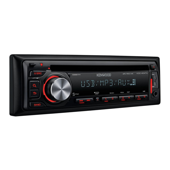
KDC-4047UA/UG/UGY/UM
KDC-414UA/414UM
KDC-MP245U
KDC-U3046/U346/U4046
SERVICE MANUAL
KDC-4047UA/UG : Panel assy (A64-5002-12)
KDC-4047UM : Panel assy (A64-5131-12)
KDC-414UM : Panel assy (A64-5132-12)
KDC-U3046 : Panel assy (A64-5008-12)
KDC-U4046 : Panel assy (A64-5016-12)
Escutcheon
* Carrying case
(B07-3270-01)
(W01-1710-05)
Mounting hardware assy
(J22-0789-03)
* Screw (4x16)
(N84-4016-48)
* Depends on the model. Refer to the parts list.
KDC-4047U
KDC-4047UM
KDC-414UM
KDC-U3046
KDC-U4046
* DC cord
* DC cord
(E30-xxxx-xx)
(E30-xxxx-xx)
* Screw set
Lever
(N99-1757-15)
(D10-7106-04) x2
© 2009-11 PRINTED IN JA PAN
B53-0767-10 ( N ) 341
KDC-4047UGY : Panel assy (A64-5004-12)
KDC-414UA : Panel assy (A64-5003-12)
KDC-MP245U : Panel assy (A64-5001-12)
KDC-U346 : Panel assy (A64-5009-12)
TDF SPARE-PANEL
MAIN UNIT NAME
TDF PARTS No.
KDC-4047UA
Y33-3242-73
KDC-4047UG
Y33-3242-74
KDC-4047UGY
Y33-3242-76
KDC-4047UM
Y33-3250-23
KDC-414UA
Y33-3242-75
KDC-414UM
Y33-3250-24
KDC-MP245U
Y33-3240-11
KDC-U3046
Y33-3250-21
KDC-U346
Y33-3250-22
KDC-U4046
Y33-3253-02
* Remote controller assy (RC-405)
(A70-2104-05)
* Plastic cabinet assy
(A02-2755-23)
This product uses Lead Free solder.
This product complies with the
KDC-4047UGY
KDC-414U
KDC-MP245U
KDC-U346
TDF NAME
TDF-4047UA
TDF-4047UG
TDF-4047UGY
TDF-4047UM
TDF-414UA
TDF-414UM
TDF-MP02DU
TDF-U3046
TDF-U346
TDF-U4046
RoHS
directive for the European market.
Advertisement
Table of Contents

Related Manuals for Kenwood KDC-4047UA


Summary of Contents for Kenwood KDC-4047UA
- Page 1 KDC-4047UA/UG/UGY/UM KDC-414UA/414UM KDC-MP245U KDC-U3046/U346/U4046 SERVICE MANUAL © 2009-11 PRINTED IN JA PAN B53-0767-10 ( N ) 341 KDC-4047UA/UG : Panel assy (A64-5002-12) KDC-4047UGY : Panel assy (A64-5004-12) KDC-4047UGY KDC-4047U KDC-4047UM : Panel assy (A64-5131-12) KDC-414UA : Panel assy (A64-5003-12) KDC-4047UM...
-
Page 2: Block Diagram
KDC-4047UA/4047UG/4047UGY/4047UM KDC-414UA/414UM/MP245U/U3046/U346/U4046 BLOCK DIAGRAM ELECTRIC UNIT (X34-660x-xx) R118 ANT. SW5V IC501 DME1 LINE MUTE PHONE CD MECHA TUNER ATOMIC Q101 (X32- ) SERVO+B BU5V POWER ACC-DET ACC-DET Q103 BU5V BU-DET BU-DET ∗ ∗ Q703-706 Q102 PRE-OUT DC-CN FRONT SURGE E-VOL... -
Page 3: Components Description
KDC-4047UA/4047UG/4047UGY/4047UM KDC-414UA/414UM/MP245U/U3046/U346/U4046 COMPONENTS DESCRIPTION ● SWITCH UNIT (X16-675x-xx) Ref. No. Application / Function Operation / Condition / Compatibility VFD Driver Remote Control Sensor ● ELECTRIC UNIT (X34-660x-xx) Ref. No. Application / Function Operation / Condition / Compatibility System μ-COM Controls FM/AM tuner, CD mechanism, panel, volume and tone. -
Page 4: Microcomputer's Terminal Description
KDC-4047UA/4047UG/4047UGY/4047UM KDC-414UA/414UM/MP245U/U3046/U346/U4046 COMPONENTS DESCRIPTION ● CD PLAYER UNIT (X32-6250-00) Ref. No. Application / Function Operation / Condition / Compatibility Driver for focusing & tracking coil, driver for sled & spindle motor, and operation for disc 4ch BTL Driver loading & ejection. - Page 5 KDC-4047UA/4047UG/4047UGY/4047UM KDC-414UA/414UM/MP245U/U3046/U346/U4046 MICROCOMPUTER’S TERMINAL DESCRIPTION Truth Value Pin No. Pin Name Application Processing / Operation / Description Table VFD data output. VFD_BLK (Pin34) is made Hi and VFD SYS DATA VFD data output the communication begins after 500ms. VFD PAN DATA...
- Page 6 KDC-4047UA/4047UG/4047UGY/4047UM KDC-414UA/414UM/MP245U/U3046/U346/U4046 MICROCOMPUTER’S TERMINAL DESCRIPTION Truth Value Pin No. Pin Name Application Processing / Operation / Description Table STANDBY source or momentary power-down: L, PWIC MUTE Power IC mute TEL mute: L MUTE I/O Mute L: Mute OFF, Hi-Z: Mute ON...
- Page 7 KDC-4047UA/4047UG/4047UGY/4047UM KDC-414UA/414UM/MP245U/U3046/U346/U4046 MICROCOMPUTER’S TERMINAL DESCRIPTION ● Bolero μ-COM : IC900 on X34- (ELECTRIC UNIT) Pin No. Pin Name Application Processing / Operation / Description MRST Reset L: Reset, H: Normal MSTOP Stop signal from system μ-com H: Normal, L: SOC stop REQ S Request signal from system μ-com...
- Page 8 KDC-4047UA/4047UG/4047UGY/4047UM KDC-414UA/414UM/MP245U/U3046/U346/U4046 MICROCOMPUTER’S TERMINAL DESCRIPTION Pin No. Pin Name Application Processing / Operation / Description Not used Output L fi xed BSIF LRCK BSIF Fixes operation mode to “1” High frequency oscillator Main clock 9.00MHz DVSS High frequency oscillator Main clock 9.00MHz...
-
Page 9: Test Mode
KDC-4047UA/4047UG/4047UGY/4047UM KDC-414UA/414UM/MP245U/U3046/U346/U4046 TEST MODE ■ Example Description of display Description A symbol “■” in the key column indicates that the key should be pressed and held. Description of display Description Disc Eject times display (Max. 65535 times). Disc Eject times display While Disc Eject times is displayed, press and hold for 2 ■... - Page 10 KDC-4047UA/4047UG/4047UGY/4047UM KDC-414UA/414UM/MP245U/U3046/U346/U4046 TEST MODE ■ Test mode default condition Description Default values Source STANDBY Display Display lights are all turned on. -10dB (“30” is displayed.) BASS BOOST SystemQ / dB EQ NATURAL (FLAT) BEEP Beeps when the key is pressed briefl y.
- Page 11 KDC-4047UA/4047UG/4047UGY/4047UM KDC-414UA/414UM/MP245U/U3046/U346/U4046 TEST MODE Description of display Description The number is the ROM correction version number. <System μ-com> <Mechanism μ-com> ROM correction version – – – – – – – – BAND When not written in yet. display <System μ-com>...
- Page 12 KDC-4047UA/4047UG/4047UGY/4047UM KDC-414UA/414UM/MP245U/U3046/U346/U4046 TEST MODE • CD information display mode (sub-mode) Description of display Description Mechanism error log 1 (Latest) XX: Error number. The “--” is displayed in case there is 1 : X no error. Mechanism error log 2 (Latest) CD mechanism error log XX: Error number.
- Page 13 KDC-4047UA/4047UG/4047UGY/4047UM KDC-414UA/414UM/MP245U/U3046/U346/U4046 TEST MODE • Design version information display mode (sub-mode) Description of display Description Destination terminal TYPE indicates μ-com destination, and indicates condition of BAND condition display the destination terminal in real-time. (forward Development ID condition rotation) Development code - Version (system μ-com) –...
- Page 14 KDC-4047UA/4047UG/4047UGY/4047UM KDC-414UA/414UM/MP245U/U3046/U346/U4046 TEST MODE • TUNER setting adjustment mode This mode is to adjust TUNER setting. Note Press this key to change the mode to the TUNER setting adjustment (Press and hold the key for 1 second). When the source is FM, frequency is switched to 98.3MHz at the start of the adjustment mode.
- Page 15 KDC-4047UA/4047UG/4047UGY/4047UM KDC-414UA/414UM/MP245U/U3046/U346/U4046 TEST MODE • Procedure in MANUAL adjustment mode Description of display Description Level Offset Press [ ] key for 500ms or longer to continuously – – adjustment (Manual) increase / decrease the adjustment value. ■ Completion of the...
- Page 16 KDC-4047UA/4047UG/4047UGY/4047UM KDC-414UA/414UM/MP245U/U3046/U346/U4046 TEST MODE • RDS automatic measurement This automatic measurement is implemented in place of the visual inspection of the PS display that had been carried out in the production line. Status Description of display Description The P-CON is forcibly turned off when the display in the left cell is shown.
- Page 17 KDC-4047UA/4047UG/4047UGY/4047UM KDC-414UA/414UM/MP245U/U3046/U346/U4046 TEST MODE • Procedure in compressed media Description of display Description – File format display (MP3) The fi le format is displayed just before the fi le playback. – File format display (WMA) – File format display (AAC) ■...
- Page 18 KDC-4047UA/4047UG/4047UGY/4047UM KDC-414UA/414UM/MP245U/U3046/U346/U4046 TEST MODE ■ Clearing DC offset error detection information (Clear the Data Flash ROM) Procedure Note While pressing and holding [3] key and [6] key, reset-start. To enter DC offset error display mode. The transition to this mode shall be possible even if the DC offset error has been detected.
- Page 19 KDC-4047UA/4047UG/4047UGY/4047UM KDC-414UA/414UM/MP245U/U3046/U346/U4046 PC BOARD (COMPONENT SIDE VIEW) (FOIL SIDE VIEW) SWITCH UNIT SWITCH UNIT X16-675x-xx (J76-0637-02) X16-675x-xx (J76-0637-02) X16-675x-xx X16-675x-xx Ref. No. Address Ref. No. Address Refer to the schematic diagram for the values of resistors and ca- pacitors.
-
Page 20: Pc Board (Component Side View)
KDC-4047UA/4047UG/4047UGY/4047UM KDC-414UA/414UM/MP245U/U3046/U346/U4046 PC BOARD (COMPONENT SIDE VIEW) ELECTRIC UNIT X34-660x-xx (J76-0640-02) PRE OUT C865 C808 R810 C873 C874 C876 C806 C872 C875 R811 C871 R812 R808 C861 C807 R715 R803 R703 R709 R710 R716 R704 R802 D106 R118 R807 D109... - Page 21 KDC-4047UA/4047UG/4047UGY/4047UM KDC-414UA/414UM/MP245U/U3046/U346/U4046 DC IN J1/L1 W103 R101 W104 R102 D106 R152 D107 D650 R151 D108 X34-660x-xx W150 Ref. No. Address W151 IC51 IC51 IC52 IC251 IC252 IC900 IC52 Q101 BU5V Q103 Q104 Q705 Q706 C208 R270 R271 R269 R203 C207...
- Page 22 KDC-4047UA/4047UG/4047UGY/4047UM KDC-414UA/414UM/MP245U/U3046/U346/U4046 PC BOARD (FOIL SIDE VIEW) ELECTRIC UNIT X34-660x-xx (J76-0640-02) R813 C866 C867 C868 C864 C862 R754 C857 AC-GND C860 C855 C853 R650 R111 R114 C103 R117 R115 R121 R116 MODE1 R401 R904 C402 C919 L904/R974 SEL1 IC53 ROM-DET-M...
- Page 23 KDC-4047UA/4047UG/4047UGY/4047UM KDC-414UA/414UM/MP245U/U3046/U346/U4046 X34-660x-xx Ref. No. Address D501 L750/R755 IC53 R555 IC501 R401 C529 R513 C530 C402 C526 C525 C532 R355 Q102 C535 R354 R527 Q105 R525/C533 R949 Q301 RSSI C508 C501 Q707 C507 C506 MRST Q902 Q903 R504 R502 Q905...
- Page 24 KDC-4047UA/4047UG/4047UGY/4047UM KDC-414UA/414UM/MP245U/U3046/U346/U4046 PC BOARD (COMPONENT SIDE VIEW) X32 B/2 12EJE CD PLAYER UNIT X32-6250-00 A/2 (J76-0556-02) 3.3V IOP- AGND RFRP BU1.5 D1.5V DGND S.GND D3.3V S.7.5V MOTOR ZDET SLED IN/EJECT SLED OUT/LOAD X32-6250-00 Ref. No. Address Refer to the schematic diagram for the values of resistors and capacitors.
- Page 25 KDC-4047UA/4047UG/4047UGY/4047UM KDC-414UA/414UM/MP245U/U3046/U346/U4046 PC BOARD (FOIL SIDE VIEW) X32 B/2 CD PLAYER UNIT X32-6250-00 A/2 (J76-0556-02) C101 X32-6250-00 Ref. No. Address Refer to the schematic diagram for the values of resistors and capacitors.
- Page 26 KDC-4047UA/4047UG/4047UGY/4047UM KDC-414UA/414UM/MP245U/U3046/U346/U4046 ELECTRIC UNIT (X34-660x-xx) R717 R713 C703 TP342 10u35 R/SL ∗ Q705,706 PRE-OUT REAR Q902,903 MUTE SW /SUB ∗ 3.3V AVR for IC900 R970 R714 C704 TP338 R718 10u35 C401 R/SR 47u16 Q903 R911 R711 R707 C705 TP343 10u35 ∗...
- Page 27 KDC-4047UA/4047UG/4047UGY/4047UM KDC-414UA/414UM/MP245U/U3046/U346/U4046 Q902,903 iPod 3.3V AVR AUTHENTICATION IC for IC900 NOT USED BU3.3V-2 BU3.3V-2 BU3.3V-2 ∗ 3.3V BU3.3V BU3.3V 3.3V R911 TP910 R908 C917 C916 Q902 R909 1K C906 C905 C901 0.01 NC20 3.3V 0.01 0.01 3.3V X900 NC19 IC950...
- Page 28 KDC-4047UA/4047UG/4047UGY/4047UM KDC-414UA/414UM/MP245U/U3046/U346/U4046 RL,RR TP316 R806 R802 C809 5.1K MUTE CONT Q105 R966 TP905 TP907 D110 TP906 TP904 R965 6.7V 6.7V MUTE 6.7V 6.7V 6.7V IC951 Q104 Bolero E2PROM SW 14 Q11,12 POWER IC MUTE CONTROL SW CONT for SERVO+B D+3.3V IC53 5.0V...
- Page 29 KDC-4047UA/4047UG/4047UGY/4047UM KDC-414UA/414UM/MP245U/U3046/U346/U4046 DC IN F1 10A (F52-0023-05) P ANT D101 ∗ D103 R101 4.7K R102 4.7K TP10 3300u16 ∗ R152 2SC4081 C859 TP17 R106 R111 R110 3.3K R120 R119 R113 100K 100K C102 R108 Q102 0.01 SURGE Q101 D109 R115 C101 0.01...
- Page 30 KDC-4047UA/4047UG/4047UGY/4047UM KDC-414UA/414UM/MP245U/U3046/U346/U4046 SWITCH UNIT (X16-675x-xx) col1 (1G) 1/2W col2 (1G) (3G-1G) ANODE CONNECTION NAME ∗ REMOTE CONTROL SENSOR ∗ 100K PAN5V LED+B ILL D GND PAN5V LED+B FL+B col1 USB D+ XBLK X34- USB GND USB D- USB5V VFD INH...
- Page 31 KDC-4047UA/4047UG/4047UGY/4047UM KDC-414UA/414UM/MP245U/U3046/U346/U4046 SWITCH UNIT (X16-675x-xx) DESTI- UNIT D52,55,63, MODEL NAME D56,58 D57,59-61 D62,65,92 D91,93 64,66-75 NATION U353 0-10 B30-1779-05 B30-1779-05 B30-1779-05 B30-1779-05 U353S 0-01 B30-1782-05 B30-1782-05 B30-1781-05 B30-1781-05 KDC-MP245U 0-10 B30-1779-05 B30-1779-05 B30-1779-05 B30-1779-05 KDC-4047UM 0-10 B30-1779-05 B30-1779-05 B30-1779-05 B30-1779-05...
- Page 32 KDC-4047UA/4047UG/4047UGY/4047UM KDC-414UA/414UM/MP245U/U3046/U346/U4046 CD PLAYER UNIT (X32-6250-00) (A/2) MECHA. (X92-) SLED OUT /LOAD TP28 4ch BTL DRIVER 1.7V TP345 7.5V D1.5V POWVCC1 R58 100 TP26 LOADING & POWGND1 SLED IN SLED /EJECT TP346 MOTOR SLIN VO1- R59 200K SPDL+ VO1+ LDIN...
- Page 33 KDC-4047UA/4047UG/4047UGY/4047UM KDC-414UA/414UM/MP245U/U3046/U346/U4046 TP44 FCS- TP47 TRK- D3.3V TP46 TRK+ D1.5V TP45 FCS+ TP111 RFRP TP84 DPU1 TP49 1.5V (X92- ) TP39 TP43 PD OPTICAL 2.2M TP42 C+D PICKUP R6 1K DVSS3R TP72 F 0.2V 1.6V TP41 A AVSS3 1.7V TP40 B DVDD3R 3.3V...
- Page 34 KDC-4047UA/4047UG/4047UGY/4047UM KDC-414UA/414UM/MP245U/U3046/U346/U4046 EXPLODED VIEW (CD MECHANISM) : N09-6108-15 : N09-6426-15 : N09-6735-05 : N09-6737-15 : N09-6738-15 : N19-2335-14 : N35-2003-48 : N39-1720-48 (X32) DPU1 (X32) Parts with the exploded numbers larger than 700 are not supplied.
-
Page 35: Exploded View (Unit)
KDC-4047UA/4047UG/4047UGY/4047UM KDC-414UA/414UM/MP245U/U3046/U346/U4046 EXPLODED VIEW (UNIT) DME1 : N35-2610-48 : N80-2006-48 : N80-2008-43 : N86-2604-43 : N86-2606-48 (X34-) : N80-3008-48 W551 : N83-3005-48 : N83-3016-48 : N86-2606-48 : N89-3010-48 (X34) (X16-) (X34) IC51 (X34-) 268 (X34- : ELECTRIC UNIT) On bottom of IC51 there is a soldering part. -
Page 36: Parts List
D62 -75 B30-1780-05 LED (1608,PG) K1 : KDC-MP245U M2 : KDC-U3046 M3 : KDC-U346 M4 : KDC-4047UM M5 : KDC-414UM Indicates safety critical com po nents. C2 : KDC-U4046 E2 : KDC-4047UA E3 : KDC-4047UG E4 : KDC-414UA E5 : KDC-4047UGY... - Page 37 CHIP R J 1/10W K1 : KDC-MP245U M2 : KDC-U3046 M3 : KDC-U346 M4 : KDC-4047UM M5 : KDC-414UM Indicates safety critical com po nents. C2 : KDC-U4046 E2 : KDC-4047UA E3 : KDC-4047UG E4 : KDC-414UA E5 : KDC-4047UGY...
-
Page 38: Electric Unit (X34-660X-Xx)
CC73GCH1H020C CHIP C 2.0PF K1M4M5 K1 : KDC-MP245U M2 : KDC-U3046 M3 : KDC-U346 M4 : KDC-4047UM M5 : KDC-414UM Indicates safety critical com po nents. C2 : KDC-U4046 E2 : KDC-4047UA E3 : KDC-4047UG E4 : KDC-414UA E5 : KDC-4047UGY... - Page 39 CHIP R J 1/10W K1 : KDC-MP245U M2 : KDC-U3046 M3 : KDC-U346 M4 : KDC-4047UM M5 : KDC-414UM Indicates safety critical com po nents. C2 : KDC-U4046 E2 : KDC-4047UA E3 : KDC-4047UG E4 : KDC-414UA E5 : KDC-4047UGY...
- Page 40 CHIP R J 1/10W M2M3C2 K1 : KDC-MP245U M2 : KDC-U3046 M3 : KDC-U346 M4 : KDC-4047UM M5 : KDC-414UM Indicates safety critical com po nents. C2 : KDC-U4046 E2 : KDC-4047UA E3 : KDC-4047UG E4 : KDC-414UA E5 : KDC-4047UGY...
-
Page 41: Mechanism Assy (X92-6370-00) Dxm-9B20W
ANALOGUE IC E3E4E5 D39-0277-15 DAMPER K1 : KDC-MP245U M2 : KDC-U3046 M3 : KDC-U346 M4 : KDC-4047UM M5 : KDC-414UM Indicates safety critical com po nents. C2 : KDC-U4046 E2 : KDC-4047UA E3 : KDC-4047UG E4 : KDC-414UA E5 : KDC-4047UGY... - Page 42 X93-2280-00 OPTICAL PICKUP ASSY K1 : KDC-MP245U M2 : KDC-U3046 M3 : KDC-U346 M4 : KDC-4047UM M5 : KDC-414UM Indicates safety critical com po nents. C2 : KDC-U4046 E2 : KDC-4047UA E3 : KDC-4047UG E4 : KDC-414UA E5 : KDC-4047UGY...
- Page 43 KDC-4047UA/4047UG/4047UGY/4047UM KDC-414UA/414UM/MP245U/U3046/U346/U4046 PARTS LIST CAPACITORS 2 2 0 • Capacitor value CC45 Color* 010 = 1pF 0 = 22pF 1 = Type ... ceramic, electrolytic, etc. 4 = Voltage rating 100 = 10pF 2 = Shape ... round, square, etc.
- Page 44 KDC-4047UA/4047UG/4047UGY/4047UM KDC-414UA/414UM/MP245U/U3046/U346/U4046 SPECIFICATIONS (KDC-MP245U) FM tuner section USB Interface Frequency range (50kHz space) ... 87.5MHz~108.0MHz USB Standard ......... USB1.1/2.0 (Full speed) Usable sensitivity (S/N=26dB) ....11.2dBf (1μV/75Ω) Maximum Supply current ........... 500mA Quieting Sensitivity (DIN S/N=46dB) ..19.2dBf (2.5μV/75Ω) File System ............. FAT16/32 Frequency response (±3dB) ......30Hz~15kHz...
- Page 45 KDC-4047UA/4047UG/4047UGY/4047UM KDC-414UA/414UM/MP245U/U3046/U346/U4046 SPECIFICATIONS (KDC-U3046/U346/U4046) FM tuner section USB Interface Frequency range USB Standard ......... USB1.1/2.0 (Full speed) 200kHz space ......... 87.9 MHz~107.9MHz Maximum Supply current ........... 500mA 50kHz space ........87.5MHz~108.0MHz File System ............. FAT16/32 Usable sensitivity (S/N=26dB) ....11.2dBf (1μV/75Ω) MP3 decode ..
- Page 46 AAC decode ..........AAC-LC “.m4a” fi les Installation Size (W x H x D) .....182 x 53 x 155mm Weight ................1.3kg KENWOOD follows a policy of continuous advancements in development. For this reason specifi cations may be changed without notice. DANGER: Please do not look at the laser beam directly during re pair or operation check.