Table of Contents
Advertisement
Power Max 926/928/1028 OXE Snowthrower
Model No. 38661—Serial No. 312000001 and Up
Model No. 38662—Serial No. 312000001 and Up
Model No. 38663—Serial No. 312000001 and Up
Introduction
This machine is intended to be used by residential
homeowners or professional, hired operators. It is
designed for removing snow from paved surfaces,
such as driveways and sidewalks, and other surfaces
for traffic on residential or commercial properties.
It is not designed for removing materials other
than snow, nor is a model with a pivoting scraper
designed for clearing off gravel surfaces.
Read this information carefully to learn how to operate
and maintain your machine properly and to avoid injury
and machine damage. You are responsible for operating
the machine properly and safely.
You may contact Toro directly at www.Toro.com for
machine and accessory information, help finding a
dealer, or to register your machine.
Whenever you need service, genuine Toro parts,
or additional information, contact an Authorized
Service Dealer or Toro Customer Service and have
the model and serial numbers of your machine ready.
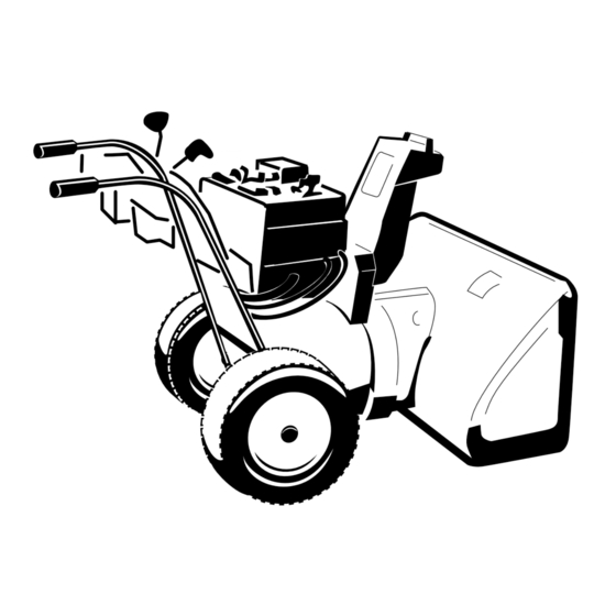
Figure 1 identifies the location of the model and serial
numbers on the machine. Write the numbers in the
space provided.
© 2012—The Toro® Company
8111 Lyndale Avenue South
Bloomington, MN 55420
G016493
1. Model and serial number location
Model No.
Serial No.
This manual identifies potential hazards and has safety
messages identified by the safety alert symbol (Figure 2),
which signals a hazard that may cause serious injury
or death if you do not follow the recommended
precautions.
1. Safety alert symbol
This manual uses 2 words to highlight information.
Important calls attention to special mechanical
information and Note emphasizes general information
worthy of special attention.
This spark ignition system complies with Canadian
ICES-002.
Register at www.Toro.com.
Form No. 3369-555 Rev C
Operator's Manual
ST OP
Figure 1
Figure 2
Original Instructions (EN)
Printed in the USA
All Rights Reserved
1
Advertisement
Table of Contents

Related Manuals for Toro Power Max 926 OXE


Summary of Contents for Toro Power Max 926 OXE
- Page 1 1. Model and serial number location and machine damage. You are responsible for operating the machine properly and safely. You may contact Toro directly at www.Toro.com for Model No. machine and accessory information, help finding a dealer, or to register your machine.
-
Page 2: Before Operating
Safety Before Operating Caution: Improper use may result in loss of fingers, hands, or feet. Read and understand the contents of this manual before operating the snowthrower There is a high-speed Become familiar with all controls and know impeller close to the how to stop the engine quickly opening. -
Page 3: Clearing A Clogged Discharge Chute
– When practical, remove gas-powered machinery • Do not run the engine indoors, except when starting from the truck or trailer and refuel it on the the engine and for transporting the machine in or ground. If this is not possible, then refuel such out of the building. -
Page 4: Toro Snowthrower Safety
• Perform only those maintenance instructions The following list contains safety information specific described in this manual. Before performing any to Toro machines or other safety information that you maintenance, service, or adjustment, stop the engine, must know. remove the key, and disconnect the wire from the spark plug. - Page 5 107-3040 1. Cutting dismemberment, impeller and cutting dismemberment, auger hazards—keep bystanders a safe distance from the snowthrower. 106-4525 Reorder part no. 112-6633 1. Fast 3. Slow 2. Forward speeds 4. Reverse speeds 112-6625 Reorder part no. 112-6629 1. Cutting/dismemberment hazard, impeller—do not place your hand in the chute;...
- Page 6 120-3065 1. Engine—stop 3. Continuous variable setting 2. Slow 4. Fast 120-9805 120-9805 1. Insert the key. 2. Prime the engine 3 times. 3. Engage the choke. 4. Pull the starter cord. 5. Once the engine is running, disengage the choke.
-
Page 7: Loose Parts
Setup Loose Parts Use the chart below to verify that all parts have been shipped. Procedure Description Qty. Handle bolts Curved washers Install the upper handle. Locknuts – No parts required Install the wheel clutch cable ends – No parts required Install the traction control linkage. -
Page 8: Installing The Upper Handle
Installing the Upper Handle Parts needed for this procedure: Handle bolts Curved washers Locknuts Procedure Figure 5 Note: Do not remove the rubber band on the cables until you have installed the upper handle. 1. Lift and rotate the upper handle and position it over the lower handle (Figure 4). -
Page 9: Installing The Traction Control Linkage
Figure 10 Figure 7 Note: The gap should be approximately the 1. Wheel clutch lever thickness of a pencil (1/4 inch or 6 mm). If it is greater, loosen the cable clamp nut, slide the cable 3. Remove the nut and washer from the handle, attach jacket up slightly, tighten the cable clamp nut, and the cable clamp on the cable to the handle, install check the gap again. -
Page 10: Installing The Chute Control Rod
Note: For easier installation, look down through the opening in the speed selector (Figure 14). Figure 14 Figure 12 1. Speed selector 1. Speed selector lever 3. Inner washer 2. Trunnion 4. Outer washer Note: To make installation easier, leave the flat washer on the trunnion (Figure 12). -
Page 11: Connecting The Wire To The Headlight
Figure 17 1. Cable clip 2. Deflector cable Figure 15 1. Short rod 2. Long chute control rod 7. Hold the blue trigger cap down and rotate the Quick Stick in a circle to ensure that the chute and deflector operate smoothly. -
Page 12: Filling The Engine With Oil
Note: Ensure that the plastic clip on the wire connector is on the bottom (Figure 18). 2. Secure a cable tie (from the loose parts bag) around the wire and the handle about an inch (2.5 cm) below the U-bolt (Figure 18). Filling the Engine with Oil No Parts Required Procedure... -
Page 13: Checking The Skids And Scraper
The machine should move rearward. If the machine does not move or moves forward, complete the following: A. Release the traction lever and stop the engine. Checking the Skids and B. Disconnect the trunnion from the speed selector Scraper lever (Figure 12). C. -
Page 14: Product Overview
Product Overview Figure 24 1. Snow cleanout tool (attached to the handle) Operation Note: Determine the left and right sides of the machine from the normal operating position. Filling the Fuel Tank DANGER Gasoline is extremely flammable and explosive. A fire or explosion from gasoline can burn you and others. -
Page 15: Starting The Engine
Starting the Engine Fill the fuel tank with fresh unleaded regular gasoline from a major name-brand service station (Figure 25). 1. Check the engine oil level. Refer to Checking the Important: To reduce starting problems, add Engine Oil Level in Maintenance. fuel stabilizer to the fuel all season, mixing it with 2. - Page 16 4. Firmly push in the primer with your thumb as 5. Move the choke to the Choke position (Figure 29). indicated by the chart below, holding the primer in for a second before releasing it each time (Figure 28). Number of pushes Temperature 15°F (-9°C) or above -10°F to 15°F (-23°C to -9°C)
-
Page 17: Stopping The Engine
Stopping the Engine 1. Move the throttle to the Slow position, and then to the Stop position (Figure 32) to kill the engine. The engine can also be stopped by pulling the ignition key outward to the middle position. G016508 Figure 31 1. -
Page 18: Operating The Traction Drive
Operating the Traction Drive CAUTION If the traction drive is not properly adjusted, the machine may move in the direction opposite of what you intended, causing injury and/or property damage. Figure 35 Carefully check the traction drive and adjust it properly, if necessary;... -
Page 19: Operating The Quick Stick
Operating the Quick Stick® Hold the blue trigger cap down to use the Quick Stick to move the discharge chute and the chute deflector. Release the trigger cap to lock the discharge chute and chute deflector into position (Figure 39). Figure 37 Operating the Auger/Impeller Drive... -
Page 20: Operating Tips
Moving the Chute Deflector force when trying to operate frozen controls. If you have difficulty operating any control or part, Hold the blue trigger cap down and move the Quick start the engine and let it run for a few minutes. Stick forward to lower the chute deflector;... -
Page 21: Recommended Maintenance Schedule(S)
• Have an Authorized Service Dealer inspect and replace the traction drive belt and/or the auger/impeller drive belt, if necessary. Important: You can find more information about maintaining and servicing your machine at www.Toro.com. Preparing for Maintenance on the dipstick, add oil. Refer to Filling the Engine with Oil. -
Page 22: Checking And Adjusting The Skids
4. Ensure that the scraper is 1/8 inch (3 mm) above and parallel to a level surface. Note: If the pavement is cracked, rough, or uneven, adjust the skids to raise the scraper. For gravel surfaces, adjust the skids further down to prevent the machine from picking up rocks. -
Page 23: Checking And Adjusting The Auger/Impeller Cable
If the left hand (traction) cable is not properly adjusted, do the following steps: 1. Loosen the jam nut. 2. Loosen or tighten the turnbuckle to adjust the pin until it is the proper gap from the front edge of the slot. -
Page 24: Checking The Auger Gearbox Oil Level
Checking the Auger Gearbox Changing the Engine Oil Oil Level Service Interval: After the first 5 hours—Change the engine oil. Service Interval: Yearly—Check the auger gearbox oil Every 50 hours—Change the engine and add oil if necessary. oil. Change the engine oil every 25 1. -
Page 25: Lubricating The Hex Shaft
(Figure 52). can result in burns. Wait until the engine is cool to replace the spark plug. Use a Toro spark plug or equivalent (Champion® RN9YC or NGK BPR6ES). 1. Remove the boot (Figure 54). Figure 52 1. Hex shaft 3. -
Page 26: Adjusting The Discharge Chute Latch
2. Clean around the base of the spark plug. Figure 57 2. Loosen the bolt on the cable clamp (Figure 58). G016646 Figure 55 3. Remove and discard the old spark plug. Note: You will need a ratchet wrench extension to remove the spark plug. -
Page 27: Replacing The Drive Belts
Replacing the Drive Belts If the auger/impeller drive belt or the traction drive belt becomes worn, oil-soaked, or otherwise damaged, have an Authorized Service Dealer replace the belt. Replacing the Headlight Bulb Figure 63 Use a GE 899 37W halogen light bulb. Do not touch the bulb with your hands or allow dirt or moisture to 5. -
Page 28: Preparing The Machine For Storage
Storage WARNING • Gasoline vapors can explode. • Do not store gasoline more than 30 days. • Do not store the machine in an enclosure near an open flame. • Allow the engine to cool before storing it. Preparing the Machine for Storage 1. -
Page 29: Troubleshooting
Troubleshooting Problem Possible Cause Corrective Action Electric starter does not turn (electric-start 1. The power cord is disconnected at the 1. Connect the power cord to the outlet models only) outlet or the machine. and/or the machine. 2. The power cord is worn, corroded, or 2. - Page 30 5. Unclog the discharge chute. 6. The auger/impeller drive belt is loose 6. Install and/or adjust the auger/impeller or is off the pulley. drive belt; refer to www.Toro.com for servicing information or take the machine to an Authorized Service Dealer.
- Page 31 As the engine owner, you should be aware that we may deny you warranty coverage if your engine or a part has failed due to abuse, neglect, If you think that your Toro Product contains a defect in materials or improper maintenance, or unapproved modifications or parts.
- Page 32 Countries Other than the United States or Canada Customers who have purchased Toro products exported from the United States or Canada should contact their Toro Distributor (Dealer) to obtain guarantee policies for your country, province, or state. If for any reason you are dissatisfied with your Distributor's service or have difficulty obtaining guarantee information, contact the Toro importer.