Table of Contents
Advertisement
Advertisement
Chapters
Table of Contents

Related Manuals for Toro Power Clear 621


Summary of Contents for Toro Power Clear 621
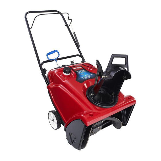
- Page 1 Residential Products ® 2014 Power Clear 418/621 Service Manual...
-
Page 3: Safety Information
PER SONAL SAFETY INSTRUCTION – informa tion and operating tips for safe operating practices. read the instruction because it has to do Operator’s manuals are available online through your Toro with your safety. Failure to comply with parts source or: the instruction may result in personal injury or even death. - Page 4 SAFETY INFORMATION NOTES Toro Single Stage Snow Service Manual...
-
Page 5: Table Of Contents
Adjusting the Control Cable .......... 2-15 Inspecting the Rotor Blades ......... 2-17 Changing the Engine Oil..........2-17 Servicing the Spark Plug ..........2-19 Replacing the Drive Belt ..........2-21 Adjusting the Quick Shoot ™ Control ......2-22 Toro Single Stage Snow Service Manual... -
Page 6: Torque Specifications
Fastener Identification Recommended fastener torque values are listed in the following tables. For critical applications, as determined by Toro, either the recommended torque or a torque that is unique to the application is clearly identified and specified in the service manual. -
Page 7: Standard Torque Values (Inch)
The tolerance is approximately ± 10% of the into threaded aluminum or brass. The nominal torque value. Thin height nuts include specific torque value should be determined jam nuts. based on the fastener size, the aluminum Toro Single Stage Snow Service Manual... -
Page 8: Other Torque Specifications
6.895 Footpounds NewtonMeters 1.356 Work Footpounds KilogramMeters 0.1383 Inchpounds KilogramCentimeters 1.152144 Quarts Liters 0.9463 Liquid Volume Gallons Liters 3.785 Liquid Flows Gallons/Minute Liters/Minute 3.785 1. Subtract 32° Temperature Fahrenheit Celsius 2. Multiply by 5/9 Toro Single Stage Snow Service Manual... -
Page 9: Equivalents & Conversions
11.112 0.9375 23.812 29/64 61/64 0.453125 11.509 0.953125 24.209 15/32 31/32 0.46875 11.906 0.96875 24.606 31/64 63/64 0.484375 12.303 0.984375 25.003 0.5000 12.700 1.000 25.400 1 mm = 0.03937 in. 0.001 in. = 0.0254mm Toro Single Stage Snow Service Manual... - Page 10 Service the spark plug and replace it if necessary. Check for loose fasteners and tighten them if necessary. Inspect the drive belt and replace it if necessary. Yearly or before storage Prepare the machine for storage. Toro Single Stage Snow Service Manual...
-
Page 11: Inspecting The Rotor Blades
NOTE To determine the proper oil level on the dipstick, refer to Fig. 002. Fig. 001 Toro Single Stage Snow Service Manual... - Page 12 Do not tip the machine all the way forward onto its nose, 11. Dispose of the used oil properly at a local or fuel may leak out of the machine. recycling center. Max fill 12 oz. (0.35 l), type: automotive detergent oil with an API Toro Single Stage Snow Service Manual...
-
Page 13: Servicing The Spark Plug
Service Interval Yearly – Service the spark plug and replace it if necessary. Use a Toro spark plug (Part No. 1191961). 1. Stop the engine and wait for all moving parts to stop. 2. Disconnect the wire from the spark plug. -
Page 14: Replacing The Drive Belt
NOTE engine pulley. The lower front corner of the drive belt cover is fastened down with a smaller bolt, a washer, and a locknut. 2-10 Toro Single Stage Snow Service Manual... - Page 15 Make sure to install the drive belt so that it sits above the two tabs on the idler arm and below the idler arm brake (Fig. 006). 7. Install the drive belt cover with the fasteners that you removed in step 1. Toro Single Stage Snow Service Manual 2-11...
-
Page 16: Storage
10. Disconnect the ignition key from the lanyard and store the ignition key in a safe place. IMPORTANT Do not remove the carburetor bowl bolt on the bottom of 11. Clean the machine. the carburetor. 2-12 Toro Single Stage Snow Service Manual... - Page 17 13. Tighten any loose fasteners. Repair or replace any damaged parts. 14. Cover the machine and store it in a clean, dry place out of the reach of children. Allow the engine to cool before storing it in any enclosure. Toro Single Stage Snow Service Manual 2-13...
- Page 18 Service the spark plug and replace it if necessary. Check for loose fasteners and tighten them if necessary. Inspect the drive belt and replace it if necessary. Yearly or before storage Prepare the machine for storage. 2-14 Toro Single Stage Snow Service Manual...
-
Page 19: Adjusting The Control Cable
3. Hook the spring to the adjuster link and slide the stop properly. spring cover over the adjuster link. 4. Check the adjustment; refer to Checking the Control Cable. Toro Single Stage Snow Service Manual 2-15... - Page 20 C. Pivot point D. Upper end of spring NOTE The belt may slip (squeal) in wet conditions; to dry out the drive system, start the rotor and run it without a load for 30 seconds. 2-16 Toro Single Stage Snow Service Manual...
-
Page 21: Inspecting The Rotor Blades
4. After draining the used oil, return the machine to the rotor blades. operating position. 5. Install the oil drain plug and tighten it securely. 6. Clean around the oil fill cap (Fig. 014). Toro Single Stage Snow Service Manual 2-17... - Page 22 Use Fig. 015 to select the best oil viscosity for the outdoor temperature range expected. Fig. 016 10. Wipe up any spilled oil. 11. Dispose of the used oil properly at a local recycling center. 2-18 Toro Single Stage Snow Service Manual...
-
Page 23: Servicing The Spark Plug
C. Discharge Chute 10. Remove the spark plug from the cylinder head. IMPORTANT Replace a cracked, fouled, or dirty spark plug. Do not clean the electrodes because grit entering the cylinder can damage the engine. Toro Single Stage Snow Service Manual 2-19... - Page 24 13. Connect the wire to the spark plug. NOTE Ensure that the breather tube is routed above the spark plug wire as shown in Fig. 020. Fig. 020 A. Breather tube B. Carburetor drain bolt 2-20 Toro Single Stage Snow Service Manual...
-
Page 25: Replacing The Drive Belt
4. Remove the rotor pulley and the drive belt (Fig. 021). NOTE Ensure that the drive belt is properly adjusted and operating; refer to “Checking the Control Cable” and “Adjusting the Control Cable.” Toro Single Stage Snow Service Manual 2-21... -
Page 26: Adjusting The Quick Shoot ™ Control
(Fig. 026). A. 1/2” (13mm) maximum slack 1. Loosen the two Quick Shoot control cable clamps (Fig. 024). Fig. 024 A. Cable Clamps Fig. 026 2-22 Toro Single Stage Snow Service Manual... - Page 27 (Fig. 028). Fig. 028 A. Upper cable casing NOTE Do not overtension the cables. If the cables are overtensioned, the Quick Shoot will be hard to operate. Toro Single Stage Snow Service Manual 2-23...
- Page 28 SPECIFICATIONS & MAINTENANCE NOTES 2-24 Toro Single Stage Snow Service Manual...
- Page 29 21 Inch Snowthrower Main Frame – Quick Shoot ..3-13 ® Power Clear 21 Inch Snowthrower Main Frame – Quick Shoot ..3-14 18 Inch Shroud Removal ..............3-15 21 Inch Shroud Removal ..............3-16 Quick Shoot Contols ................3-17 Toro Single Stage Snow Service Manual...
-
Page 30: Power Clear
CHASSIS ® Power Clear - 18 Inch Snowthrower Main Frame – Lower Fig. 001 A. Side plate RH B. Side plate LH C. Belt Cover D. Model/Serial Decal Toro Single Stage Snow Service Manual... -
Page 31: Power Clear ® 18 Inch Snowthrower Main Frame - Housing
CHASSIS ® Power Clear - 18 Inch Snowthrower Main Frame – Housing Fig. 002 A. Lower Handle B. Scraper C. Chute Retainer Toro Single Stage Snow Service Manual... -
Page 32: Power Clear ® 18 Inch Snowthrower Main Frame - Shroud
CHASSIS ® Power Clear - 18 Inch Snowthrower Main Frame – Shroud Fig. 003 A. Shroud Assembly B. Lower Shroud LH C. Lower Shroud RH Toro Single Stage Snow Service Manual... -
Page 33: Power Clear
- 18 Inch Snowthrower Main Frame – Upper Handle Fig. 004 A. Clutch Bail E. Spring Cover B. Handle Knob F. Upper Handle Assembly C. Cable Clutch Adjuster G. Recoil Handle D. Clutch Spring Toro Single Stage Snow Service Manual... -
Page 34: Power Clear ® 18 Inch Snowthrower Main Frame - Lower
CHASSIS ® Power Clear - 18 Inch Snowthrower Main Frame – Lower Fig. 005 A. Chute Deflector Assembly B. Discharge Chute C. Chute Handle Toro Single Stage Snow Service Manual... -
Page 35: Power Clear
- 21 Inch Snowthrower Main Frame – Housing Fig. 006 A. Scraper Blade E. Extension Spring B. Auger Housing F. Lower Chute C. Frame Brace G. Belt Cover D. Clutch Cable Guide H. Model/Serial Decal Toro Single Stage Snow Service Manual... -
Page 36: Power Clear
CHASSIS ® Power Clear - 21 Inch Snowthrower Main Frame – Chute Fig. 007 A. Chute Ring E. Chute Seal Ring B. Discharge Chute Assembly F. Chute Ring Gear C. Chute Deflector D. Chute Control Handle Toro Single Stage Snow Service Manual... -
Page 37: Power Clear
CHASSIS ® Power Clear - 21 Inch Snowthrower Main Frame – Chute Fig. 008 A. Deflector Trigger E. Chute I. Detent Paw M. Seal Ring Chute B. Chute Deflector F. Pinion Gear J. Chute Support Ring C. Ratchet Deflector Hinge G. Pinion Bracket K. Chute Ring Gear D. Deflector Seal H. Cable Retainer L. Chute Handle Toro Single Stage Snow Service Manual... -
Page 38: Power Clear
Main Frame – Handles Fig. 009 A. Upper Handle Assembly E. Clutch Cable Adjuster I. Rope Guide B. Control Bail F. Handle Lock J. Recoil Handle C. Spring Cover G. Lower Handle D. Clutch Extension Spring H. Handle Knob 3-10 Toro Single Stage Snow Service Manual... -
Page 39: Power Clear
Main Frame – Power Shoot Fig. 010 A. Slider Handle RH E. Slider Pulley I. Trigger B. Short Chute Cable F. Slider Track J. Cable Bracket C. Long Chute Cable G. Chute Lock Plate D. Pulley Cover H. Slider Handle LH Toro Single Stage Snow Service Manual 3-11... -
Page 40: Power Clear
- 21 Inch Snowthrower Main Frame – Shroud Fig. 011 A. Gas Cap E. Lower Shroud H. Primer Bulb B. Shroud Assembly F. Choke Knob I. Exhaust Baffle C. Tank Seal G. On/Off Switch D. Fuel Tank 3-12 Toro Single Stage Snow Service Manual... - Page 41 CHASSIS ® Power Clear - 21 Inch Snowthrower Main Frame – Quick Shoot Illustration 2 Illustration 1 Illustration 4 Illustration 3 Fig. 012 Toro Single Stage Snow Service Manual 3-13...
- Page 42 CHASSIS ® Power Clear - 21 Inch Snowthrower Main Frame – Quick Shoot Illustration 5 Illustration 6 Illustration 7 Fig. 013 3-14 Toro Single Stage Snow Service Manual...
-
Page 43: 18 Inch Shroud Removal
(B) (Fig. 014). Fig. 016 Fig. 014 2. Remove the belt cover. Disconnect the clutch cable from the belt guide. Slide the cable through the housing (Fig. 015). Fig. 015 Toro Single Stage Snow Service Manual 3-15... - Page 44 (Fig. 017). Fig. 019 4. Remove the shroud (Fig. 020). Fig. 017 2. Remove the single screw holding the chute seal ring Remove the ring (Fig. 018). Fig. 020 Fig. 018 3-16 Toro Single Stage Snow Service Manual...
-
Page 45: Quick Shoot Contols
Fig. 023 Fig. 021 4. Turn the gear assembly over and remove the cable retainer (Fig. 024). 2. Remove the complete assembly. Remove pinion spacer sleeve (A) Fig. 022). Fig. 024 Fig. 022 Toro Single Stage Snow Service Manual 3-17... - Page 46 Insert the barrel end of the cable into the hole and secure the cable under the tab in the gear (Fig. 026). Fig. 028 Fig. 026 3-18 Toro Single Stage Snow Service Manual...
- Page 47 8 ft-lbs (11 Nm) (Fig. 033). Fig. 030 11. When the cables are routed correctly the cables and gear should look like this (Fig. 031). Fig. 033 NOTE Do not overtighten! Fig. 031 Toro Single Stage Snow Service Manual 3-19...
- Page 48 CHASSIS NOTES 3-20 Toro Single Stage Snow Service Manual...
- Page 49 ...4-5 18 Inch Rotor Removal & Replacement ......4-6 21 Inch Rotor Removal & Replacement ......4-8 Paddle Replacement (All Models) ........4-10 18 Inch Scraper Removal & Replacement .......4-11 21 Inch Pivoting Scraper Removal & Replacement..4-12 Toro Single Stage Snow Service Manual...
- Page 50 POWER PROPEL SYSTEM ® Power Clear - 18 Inch Snowthrower Rotor Assembly Fig. 001 A. Side Plate Cap E. Rotor Blade B. Ball Bearing F. Rotor Assembly C. Bearing Flange D. Thrust Washer Toro Single Stage Snow Service Manual...
- Page 51 POWER PROPEL SYSTEM ® Power Clear - 18 Inch Snowthrower Drive System Fig. 002 A. Engine Pulley E. Idler Arm B. Ribbed V-Belt F. Rotor Pulley Assembly C. Belt Guide G. Idler Pulley D. Clutch Cable Toro Single Stage Snow Service Manual...
- Page 52 POWER PROPEL SYSTEM ® Power Clear - 21 Inch Snowthrower Rotor Assembly Fig. 003 A. Rotor Blade B. Rotor Toro Single Stage Snow Service Manual...
- Page 53 Power Clear - 21 Inch Snowthrower Drive System Fig. 004 A. Rotor Pulley Assembly E. Idler Arm B. Drive Belt F. Engine Pulley C. Idler Pulley G. Pinion Bracket D. Clutch Cable H. Cable Retainer Toro Single Stage Snow Service Manual...
- Page 54 2. Remove the three rotor bearing screws on the belt 4. Remove three bolts holding the side plate to the side of the housing (Fig. 006). rotor housing (A). Loosen the wheel bracket bolts (B) (Fig. 008). Fig. 006 Fig. 008 Toro Single Stage Snow Service Manual...
- Page 55 8 ft-lbs (11 Nm) (Fig. 013). Fig. 010 Fig. 013 7. Replace rotor parts as required (Fig. 011). 10. Re-install the belt cover. Torque bolts to 8 ft-lbs (11 Nm). Fig. 011 Toro Single Stage Snow Service Manual...
- Page 56 Fig. 015 Fig. 017 2. Remove the three rotor bearing screws on the belt 4. Remove the rotor assembly from the housing. side of the housing (Fig. 016). (Fig. 018). Fig. 016 Fig. 018 Toro Single Stage Snow Service Manual...
- Page 57 7. Re-install the bearing spacer and bolt. Torque bolt to rotor pulley bolt to 8 ft-lbs (11 Nm) (Fig. 022). 20 ft-lbs (27 Nm) (Fig. 020). Fig. 022 Fig. 020 10. Re-install the belt cover. Torque the bolts to 8 ft-lbs (11 Nm). Toro Single Stage Snow Service Manual...
- Page 58 Fig. 023 Fig. 025 2. Remove the two inner bolts holding the paddle to the rotor (A) (Fig. 024). 4. Install new paddles and install rotor assembly back into the housing. Fig. 024 4-10 Toro Single Stage Snow Service Manual...
- Page 59 18 Inch Scraper Removal & Replacement 1. Remove the three bolts attaching the scraper to the frame. 2. Install a new scraper. Torque bolts to 16 in-lbs (0.184 kg-m) (Fig. 26). Fig. 026 Toro Single Stage Snow Service Manual 4-11...
- Page 60 4. Insert new scraper. Re-install springs and bolts. Torque bolts to 20 ft-lbs (27 Nm) (Fig. 30). Fig. 027 2. Remove the bolts from each side of the scraper (Fig. 028). Fig. 030 Fig. 028 Toro Single Stage Snow Service Manual 4-12...
- Page 61 Power Clear ® - 21 Inch Snowthrower Engine Mounting ..5-3 Engine Removal 18 Inch Models ...........5-4 Engine Installation 18 Inch Models ........5-5 Engine Removal 21 Inch Models ...........5-6 Engine Installation 21 Inch Models ........5-8 Toro Single Stage Snow Service Manual...
- Page 62 ENGINE MOUNTING ® Power Clear - 18 Inch Snowthrower Engine Mounting Fig. 001 A. Tank Seal B. Woodruff Key C. Choke Lever Toro Single Stage Snow Service Manual...
- Page 63 ENGINE MOUNTING ® Power Clear - 21 Inch Snowthrower Engine Mounting Fig. 002 A. LC168FS Engine E. Choke Link Knob B. PTO Engine Plate C. Side Engine Support D. Engine Support Toro Single Stage Snow Service Manual...
-
Page 64: Engine Removal 18 Inch Models
4. From the underside of the chassis, remove the two engine mounting bolts (A) (Fig. 004). Fig. 006 Fig. 004 For engine service information, see Single Stage Snow Engine Service Manual LC154FS/ LC154FDS (87cc), PN 492-9233 or LC168F/LC168FD (163 cc), PN 492-9230 Toro Single Stage Snow Service Manual... -
Page 65: Engine Installation 18 Inch Models
4. Install the belt as outlined in chapter 2. Install belt cover. Install shroud as outlined in chapter 2. 2. From the underside of the chassis, install the two engine mounting bolts (A). Torque to 14-18 ft-lbs (19-25 Nm) (Fig. 008). Fig. 008 Toro Single Stage Snow Service Manual... -
Page 66: Engine Removal 21 Inch Models
6. Disconnect the primer hose from the primer bulb and remove the ignition wires from the ignition switch. (Fig. 013). Fig. 010 4. Untie the knot on the recoil handle (Fig. 011). Fig. 013 Fig. 011 Toro Single Stage Snow Service Manual... - Page 67 10. On some models, the engine pulley has two set screws. One is an allen head set screw and the other is a bolt. Be sure to loosen both set screws before attempting removal (Fig. 016). Fig. 016 Toro Single Stage Snow Service Manual...
-
Page 68: Engine Installation 21 Inch Models
(A). Torque to 14-18 ft-lbs (19-25 Nm) (Fig. 020). 4. Connect the primer hose to the primer bulb and plug the ignition wires into the ignition switch (Fig. 022). Fig. 020 Fig. 022 Toro Single Stage Snow Service Manual... - Page 69 6. Slide the choke wire through the lower shroud and install the choke knob and screw (Fig. 024). Fig. 024 7. Install the fuel tank and connect the fuel line. 8. Install the belt cover and shroud as outlined in chapter 2. Toro Single Stage Snow Service Manual...
- Page 70 ENGINE MOUNTING NOTES 5-10 Toro Single Stage Snow Service Manual...
- Page 72 Residential Products ® ® 2014 Power Clear 2014 Power Clear 418/621 418/621 Service Manual Service Manual Form Number 492-9340...