Table of Contents
Advertisement
SPLIT TYPE
AIR CONDITIONER
CASSETTE
Models
Indoor unit
Outdoor unit
AUU18RCLX
AOU18RLX
AUU24RCLX
AOU24RLX
AUU36RCLX
AOU36RLX
AUU42RCLX
AOU42RLX
C ON TE N TS
SPECIFICATIONS . . . . . . . . . . . . . . . . . . . . . . 1
DIMENSIONS . . . . . . . . . . . . . . . . . . . . . . . . . . 3
REFRIGERANT SYSTEM DIAGRAM . . . . . . . 7
CIRCUIT DIAGRAM . . . . . . . . . . . . . . . . . . . . . 9
INDOOR PCB CIRCUIT DIAGRAM . . . . . . .
ERROR CONTENTS . . . . . . . . . . . . . . . . . . . .
DISASSEMBLY ILLUSTRATION . . . . . . . . . . 23
PARTS LIST . . . . . . . . . . . . . . . . . . . . . . . . . . 38
STANDARD ACCESSORIES . . . . . . . . . . . . . 42
type
(60Hz)
13
. . . . . 15
21
Advertisement
Table of Contents

Related Manuals for Fujitsu AUU18RCLX


Summary of Contents for Fujitsu AUU18RCLX
-
Page 1: Table Of Contents
SPLIT TYPE AIR CONDITIONER CASSETTE type (60Hz) Models Indoor unit Outdoor unit AUU18RCLX AOU18RLX AUU24RCLX AOU24RLX AUU36RCLX AOU36RLX AUU42RCLX AOU42RLX C ON TE N TS SPECIFICATIONS ..... . 1 DIMENSIONS . -
Page 2: Specifications
S PEC I FI CA T I O NS TYPE COOLING & HEATING INDOOR UNIT AUU18RCLX AUU24RCLX AUU36RCLX AUU42RCLX OUTDOOR UNIT AOU18RLX AOU24RLX AOU36RLX AOU42RLX COOLING CAPACITY 17,800 / 17,800 BTU/h 22,200 / 22,200 BTU/h 34,100 / 33,500 BTU/h 42,700 / 41,700 BTU/h... - Page 3 TYPE COOLING & HEATING INDOOR UNIT AUU18RCLX AUU24RCLX AUU36RCLX AUU42RCLX AOU18RLX AOU24RLX AOU36RLX AOU42RLX OUTDOOR UNIT NOISE LEVEL HIGH-SPEED 42.0 dB 45.0 dB 48.0 dB 50.0 dB INDOOR UNIT MED-SPEED 39.0 dB 43.0 dB 45.0 dB 48.0 dB 36.0 dB 38.0 dB...
-
Page 4: Dimensions
D IME N SIO N S INDOOR UNIT Models : AUU18RCLX, AUU24RCLX Unit : inch (mm) 29-17/32" (750mm) 37" (940) 32-3/4" (830mm) Drain inside Dia. ø1-1/4" (ø32) outside Dia. ø1-1/2" (ø37) 11-3/4" 11-3/4" (298.5) (298.5) 12" (305.5) 9-25/32" 12" (305.5) 9-25/32"... - Page 5 INDOOR UNIT Models : AUU36RCLX, AUU42RCLX Unit : inch (mm) 37" (940mm) 29-17/32" (750mm) 32-3/4" (830mm) Drain pipe (I.D.1-1/4" (32mm)) (O.D.1-1/2" (37mm)) Drain pipe (I.D.1-1/4" (32mm)) 11-3/4" 11-3/4" (298.5mm) (O.D.1-1/2" (37mm)) (298.5mm) 12" 9-25/32" 12" 9-25/32" (305.5mm) (248.5mm) (305.5mm) (248.5mm) 2006.03.03...
- Page 6 OUTDOOR UNIT Models: AOU18RLX, AOU24RLX, AOU36RLX Unit : inch (mm) 1-1/4" 1/2" 3"(77) (31) (12) 13" (330) 35-1/2" (900) 15-3/4" (400) 25-5/8" (650) Air Flow 5-3/4" (147) 6-3/4" (170) 2005.12.21...
- Page 7 OUTDOOR UNIT Model : AOU42RLX Unit : inch (mm) 1-1/4" 1/2" (31) (12) 35-1/2" (900) 3"(77) 13" (330) 15-3/4" (400) 25-5/8" (650) Air Flow 5-3/4" (147) 6-3/4" (170) 2005.12.21...
-
Page 8: Refrigerant System Diagram
R EF RIG ER AN T S Y S T E M DI AGRA M Models : AUU18RCLX / AOU18RLX OUTDOOR UNIT INDOOR UNIT Pressure Refrigerant Pipe Check Valve 12.7mm (1/2") High Pressure Switch Charging Valve 4-way Valve Evaporator Condenser... - Page 9 Models : AUU24RCLX / AOU24RLX AUU36RCLX / AOU36RLX INDOOR UNIT OUTDOOR UNIT Pressure Refrigerant Pipe Check Valve 15.88mm (5/8") High Pressure Switch Charging Valve 4-way Valve Evaporator Condenser Accumulator Compressor Expansion Refrigerant Pipe Valve 9.52mm (3/8") Strainer Strainer Charging Valve Models : AUU42RCLX / AOU42RLX INDOOR UNIT OUTDOOR UNIT...
-
Page 10: Circuit Diagram
C I R C UI T DI AG R AM Models : AUU18RCLX, AUU24RCLX PIPE TEMPERATURE THERMISTOR ROOM TEMPERATURE THERMISTOR TO REMOTE CONTROL UNIT BROWN BROWN ORANGE ORANGE STEP MOTOR TERMINAL YELLOW YELLOW WHITE WHITE WHITE BLACK BLACK BLACK FLOAT SWITCH... - Page 11 Model : AOU18RLX, AOU24RLX OUTDOOR TEMPERATURE BLACK THERMISTOR PIPE TEMPERATURE BLUE THERMISTOR COMPRESSOR TEMPERATURE BROWN BROWN THERMISTOR DISCHARG TEMPERATURE THERMISTOR BLACK HEAT SINK TEMPERATURE THERMISTOR EMI FILTER CN21 CN22 CN23 CN26 CN25 CONNECTOR HIGH PRESSURE SWITCH CN37 W305 WHITE WHITE COMPRESSOR W304 FUSE...
- Page 12 Model : AOU36RLX OUTDOOR TEMPERATURE PIPE TEMPERATURE THERMISTOR BLUE THERMISTOR BLACK COMPRESSOR TEMPERATURE BROWN THERMISTOR DISCHARGE TEMPERATURE BROWN THERMISTOR HEAT SINK TEMPERATURE BLACK THERMISTOR EMI FILTER CONNECTOR CN21 CN22 CN23 CN26 CN25 COMPRESSOR CN37 HIGH PRESSURE SWITCH W305 WHITE WHITE W304 FUSE SOLENOID COIL...
- Page 13 Model : AOU42RLX OUTDOOR TEMPERATURE THERMISTOR BLUE PIPE TEMPERATURE BLACK THERMISTOR COMPRESSOR TEMPERATURE BROWN THERMISTOR DISCHARGE BROWN TEMPERATURE HEAT SINK TEMPERATURE BLACK THERMISTOR THERMISTOR EMI FILTER CN21 CN22 CN23 CN26 CN25 CONNECTOR COMPRESSOR HIGH PRESSURE SWITCH CN37 W305 WHITE WHITE W304 BLACK FUSE...
-
Page 22: Error Contents
E R R O R C O N T E NT S (indoor unit) Error code Error contents (1) Stop the air conditioner operation. (2) Press the master control button and the fan control button simultane- Outdoor signal abnormal ously for 2 seconds or more to start the test run. Excessive outdoor pressure (permanent stop) Compressor temperature sensor Pressure switch error... - Page 23 ER RO R C O N T E N T S (o utd oo r u n i t ) 1. Make a TEST RUN in accordance with the in- 2. When the product is operating: stallation instruction sheet for the indoor unit. Press the PUMP DOWN switch on the outdoor unit.
-
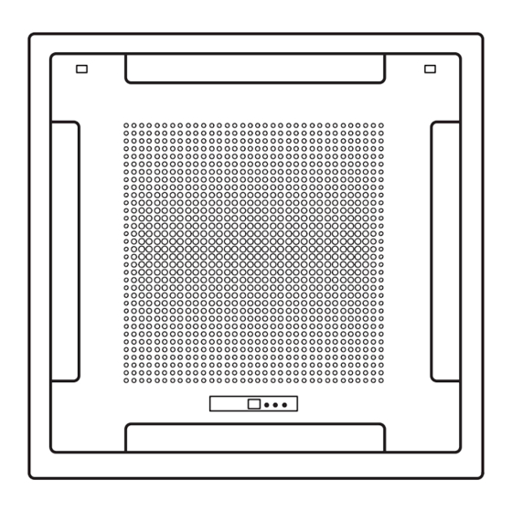
Page 24: Disassembly Illustration
DI SA SS EM BLY I LLUS TRAT ION Models : AUU18RCLX AUU24RCLX AUU36RCLX AUU42RCLX 876-2 834-2 472-1 472-2 472-4 777-2 253-A 481-1 472-3 777-1 472-5 472-5 472-5 472-5 2006.03.03... - Page 25 Models : AUU18RCLX AUU24RCLX 460-1 460-2 835 482 815-1 541-1 476-2 146-2 337-2 146-1 337-1 337-1 834-1 2006.01.17...
- Page 26 Models : AUU36RCLX AUU42RCLX 460-1 460-2 815-1 541-1 476-2 146-1 337-2 146-2 337-1 337-1 834-1 2006.03.03...
- Page 27 Models : AUU18RCLX AUU24RCLX AUU36RCLX AUU42RCLX 815-2 320-1 320-1 381-4 381-4 731-2 2006.03.03...
- Page 28 Models : AUU18RCLX AUU24RCLX 184-1 2006.03.03...
- Page 29 Model : AUU36RCLX 184-1 146-1 146-2 2006.03.03...
- Page 30 Model : AUU42RCLX 184-1 2006.03.03...
- Page 31 Models : AOU18RLX AOU24RLX AOU36RLX 2005.12.22...
- Page 32 Models : AOU18RLX AOU24RLX AOU36RLX 17-1 18-1 2006.06.13...
- Page 33 Models : AOU18RLX AOU24RLX AOU36RLX 2005.12.22...
- Page 34 Models : AOU18RLX AOU24RLX AOU36RLX 33 34 2005.12.22...
- Page 35 Model : AOU42RLX 2005.12.22...
- Page 36 Model : AOU42RLX 2005.12.22...
- Page 37 Model : AOU42RLX 2005.12.22...
- Page 38 Model : AOU42RLX 2005.12.22...
-
Page 39: Parts List
PA R TS LI ST INDOOR UNIT Part No. Part No. Ref. Ord. Ref. Ord. Description Description Q'ty Q'ty AUU18RCLX AUU24RCLX AUU18RCLX AUU24RCLX Control Box Assy 9368533007 9368533007 472-3 RFM (Grille)-C 9362740005 9362740005 Capacitor (Fan Motor) 9900270049 9900270049 472-4 RFM (Grille)-D... - Page 40 INDOOR UNIT Parts No. Parts No. Ref. Ord. Ref. Ord. Description Description Q'ty Q'ty AUU36RCLX AUU42RCLX AUU36RCLX AUU42RCLX Control Box Assy 9368533007 9368533007 472-3 Grille Reinforcement-T (C) 9362740005 9362740005 Capacitor (Fan Motor) 9900270162 9900270162 472-4 Grille Reinforcement-T (D) 9362741002 9362741002 Decoration Plate 9362787000 9362787000...
- Page 41 OUTDOOR UNIT Part No. Ref. Ord. Description Q'ty AOU18RLX AOU24RLX AOU36RLX Top Panel Sub Assy 9374417025 9374417025 9374417025 Front Panel 9374094066 9374094066 9374094066 Fan Guard 9374330010 9374330010 9374330010 Grip Side 9374173013 9374173013 9374173013 Service Panel Sub Assy 9374415038 9374415038 9374415038 Right Panel 9374095148 9374095148...
- Page 42 OUTDOOR UNIT Parts No. Ref. Ord. Description Q'ty AOU42RLX Top Panel Sub Assy 9374417025 Front Panel X 9374094028 Fan Guard 9374330010 Grip Side 9374173013 Service Panel Sub Assy 9374415014 Right Panel Sub Assy 9374416080 Valve Cover 9374174010 Propeller Fan Assy 9366378020 Motor DC Brushless 9602114016...
-
Page 43: Standard Accessories
S T AN DA RD AC CE S S ORI E S INDOOR UNIT ACCESSORIES Name and Shape Q’ty Application Coupler heat For indoor side pipe joint insulation Tapping Screw For installing the remote (flush heads) controller Special nut A For installing indoor unit (large flange) Special nut B... -
Page 44: Connection Pipe Requirement
WARNING For the air conditioner to operate satisfactorily. install it as outlined in this installation instruction sheet. Connect the indoor unit and outdoor unit with the room air conditioner piping and cords available standards parts. This installation instruction sheet describes the correct connections using the installation set available from our standard parts. Installation work must be performed in accordance with national wiring standards by authorized personnel only. - Page 45 0512G2977...