Table of Contents
Advertisement
Advertisement
Table of Contents

Related Manuals for Panasonic VL-SWD501


Summary of Contents for Panasonic VL-SWD501
- Page 1 2013 Wireless Video Intercom INSTALLATION GUIDE...
-
Page 2: Table Of Contents
INDEX System configuration and wiring System configuration and wiring Installing Wireless Sensor Cameras Installing Wireless Sensor Cameras VL-SWD501 System Component …….………………………. 4 Install the wireless sensor camera ..………………………………… 29 VL-SWD501EX wiring schematic diagram …………..… 5 If connecting an external sensor …..…………..…………………….. -
Page 3: System Configuration And Wiring
System configuration and wiring System configuration and wiring... -
Page 4: Vl-Swd501 System Component
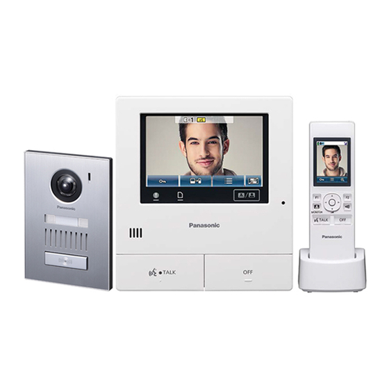
SWD501 System Component SWD501 System Component Basic System Component VL-SWD501 Up to Up to 5-inch 2.2-inch TFT wide screen colour LCD touch panel Door Station (Doorphone) Main Monitor Station Wireless Monitor Station (Main monitor) (Sub monitor) Optional Expandability Up to... -
Page 5: Vl-Swd501Ex Wiring Schematic Diagram
SWD501EX wiring schematic diagram SWD501EX wiring schematic diagram Door Station 1 Main Monitor Station Electric lock (Electric vehicle gate lock) 12 VAC/DC Power Electric lock supply (Electric door lock) 12 VAC/DC Power supply Door Station 2 220-240 VAC Electric lock (Electric vehicle gate lock) 12 VAC/DC Power... -
Page 6: Vl-Swd501Ex Wiring Type And Length
SWD501EX wiring type and length SWD501EX wiring type and length Wire type*1 Wiring run Diameter Length (Max.) φ 0.65 mm 22 AWG 100 m Main Monitor Station – φ 1.0 mm 18 AWG 130 m Door station φ 0.5 mm CAT 5 50 m φ... - Page 7 Door Station Installation Door Station Installation...
-
Page 8: Door Station Installation Installing The Door Station (Vl-V554Ex)
Door Station Installation Door Station Installation Installing the door station (VL-V554EX) Step 2 Use a hex wrench to loosen screw A and Step 1 Attach the mounting base to the wall remove the front panel of the door station. securely. Front panel Mounting base Screws x 2 *... - Page 9 Door Station Installation Door Station Installation Installing the door station (VL-V554EX) Step 4 Attach the door station to the mounting base. Important • On the bottom surface of the door station and the mounting base, there are holes to allow water to drain. Do not cover them up when installing.
-
Page 10: Installing The Door Station (Vl-V554Uex)
Door Station Installation Door Station Installation Installing the door station (VL-V554UEX) Step 2 Use a hex wrench to loosen screw A and Step 1 Install the flush mounting box in the wall. remove the front panel of the door station. Flush mounting box Front panel 100mm... - Page 11 Door Station Installation Door Station Installation Installing the door station (VL-V554UEX) Step 4 Attach the door station to the flush Important mounting box. • On the bottom surface of the door station and the mounting base, there are holes to allow water to drain. Do not cover them up when installing.
-
Page 12: Door Station Installation Position
Door Station Installation Door Station Installation Door station installation position Installation height and area visible by the camera lens You can use the [Wide/Zoom settings] setting on the main monitor station to select the area that is visible when a visitor calls; available settings are [Wide], [Zoom], and [All] (entire image display). - Page 13 Door Station Installation Door Station Installation Door station installation position When set to zoom Displays a portion of the wide image at 2 times the size. •Because a digital zoom is used, the image quality of zoom display is lower than that of wide display or entire image display.
- Page 14 Door Station Installation Door Station Installation Door station installation position Installation Position - Zoom You can use the main monitor station’s [Zoom position settings] setting to select the desired area visible when zooming. Refer to Installation Position and configure the main monitor station. Up and down Centre (default) Down...
- Page 15 Door Station Installation Door Station Installation Door station installation position Entire image display The area above and below the wide image is visible. Image range (Units: mm) Approx. 115° Approx. 2,250 Centre of door station View when looking Image displayed on from above main monitor station Approx.
- Page 16 Main Monitor Station Installation Main Monitor Station Installation...
-
Page 17: Main Monitor Station Installation
Main Monitor Station Installation Main Monitor Station Installation Installing the main monitor station Attach the mounting bracket to the wall securely. Step 1 ・Install the mounting bracket on a vertical flat wall. Mounting bracket Vertical, flat wall Hole in wall 60 mm 83.5 mm Screws... - Page 18 Main Monitor Station Installation Main Monitor Station Installation Installing the main monitor station Step 2 Connect the DC cable and wires. How to make wiring connections: How to connect the DC cable: While pressing on the button with a Remove screw A and then remove the terminal cover. pointed object such as a screwdriver, Loosen screw B and push in the wires of the DC cable insert the wire into the terminal...
-
Page 19: Main Monitor Station Installation Position
Main Monitor Station Installation Main Monitor Station Installation Main monitor station installation position About the installation position of the main monitor station and mounting bracket • Place the main monitor station in a location that your eyes are the same height as the centre of the display. •... - Page 20 Power Supply Unit Installation Power Supply Unit Installation...
-
Page 21: Installing The Power Supply Unit (Vl-Ps241)
Power Supply Unit Installation Power Supply Unit Installation Installing the power supply unit (VL-PS240) How to connect the power cable (AC/DC) Step 3 Connect the AC/DC cable to the AC IN Connect the power supply unit and AC/DC cables. terminal/DC OUT terminal on the top and bottom of the power supply unit, and then Step 1 Strip the AC/DC cables as follows:... -
Page 22: Power Supply Unit Installation
Power Supply Unit Installation Power Supply Unit Installation Installing the power supply unit (VL-PS240) About the installation location • The device must be installed inside an electrical panel or cabinet. • A readily accessible disconnect device shall be incorporated external to the equipment. ... -
Page 23: Initial Setup Initial Setup
Initial Setup Initial Setup... -
Page 24: Setting The Date And Time
Initial Setup Initial Setup Setting the language, date and time This operation can only be performed on the main monitor station. A language selection screen is displayed when the main monitor station is first used. Step 1 Step 3 Touch the language that you want to Touch [OK] to complete the settings. -
Page 25: Changing The Date And Time
Initial Setup Initial Setup Changing the date and time This operation can only be performed on the main monitor station. Touch the screen to display the Step 1 Step 4 Touch [Initial settings]. top screen. Step 5 Touch [Time and date settings]. Step 2 Touch Step 6... -
Page 26: Setting Demo Mode
Initial Setup Initial Setup Setting Demo mode Demo mode is a special mode for using the product in a display at a store. Step 1 From the top menu, touch Step 4 Touch [Demo mode]. Touch [Next]. Step 5 Step 2 Touch Step 6 Select the setting to use from [On] or... -
Page 27: Registering Wireless Monitor Stations
Initial Setup Initial Setup Registering wireless monitor stations Additional wireless monitor stations can be registered. Main monitor station operations Wireless Monitor Station operations Main monitor station operations → Step 4 Step 1 When "Please register the device." is From the top menu, touch →[Register/Cancel] →... - Page 28 Installing Wireless Sensor Cameras Installing Wireless Sensor Cameras...
-
Page 29: Installing Wireless Sensor Cameras
Installing Wireless Sensor Cameras Installing Wireless Sensor Cameras Install the wireless sensor camera Attach the wall mount bracket to the wall that has the cable access hole and caulk the bracket. Step 1 Secure the wall mount bracket. Use a water-resistant sealant to caulk around the bracket, except for the bottom part. - Page 30 Installing Wireless Sensor Cameras Installing Wireless Sensor Cameras Install the wireless sensor camera Step 2 Open the cover on the rear and connect the DC cable. Open the cover. Remove the water-resistant rubber (1) from the wireless sensor camera and attach it to the DC cable. Cover Pass the DC cable through the recessed area of the water-...
-
Page 31: If Connecting An External Sensor
Installing Wireless Sensor Cameras Installing Wireless Sensor Cameras If connecting an external sensor Step 3 Connect wires to the external input terminal. Strip the wires. 32 mm 12 mm Remove the water-resistant rubber (3) from the wireless sensor camera and attach it to the wires. Connect the wires to the terminals (4) and reattach the water-resistant rubber and secure it in its original position... - Page 32 Installing Wireless Sensor Cameras Installing Wireless Sensor Cameras After you have adjusted the angle, attach Step 6 Step 8 Adjusting the wireless sensor camera angle. the safety wire to the wall. Adjusting angle left Screw (1) and right: Washer Loosen screw (1) and Safety wire adjust the angle left or right.
-
Page 33: Using External Sensor (About The External Input Terminal )
Using external sensors Using external sensors About the external input terminal (for an external sensor connection) Choose an external sensor that is compatible with the specifications of the external input terminal. •After connection, use the main monitor station to select the contact type ([Make contact] or [Break contact]) that matches the device. -
Page 34: Wire Type And Length
Wire type and length Wire type and length Wire type*1 Wiring run Diameter Length (Max.) φ 0.65 mm 50 m 22 AWG ① Wireless Camera - Power supply unit φ 1.0 mm 100 m 18 AWG φ 1.2 mm 17 AWG No requirement ②... -
Page 35: Installation Location For The Wireless Sensor Camera
Installation location for the wireless sensor camera Installation location for the wireless sensor camera If your Video Intercom System includes a sub monitor, it can be used to easily check the signal status. (If there is no sub monitor, use a camera.) ■Using the sub monitor to confirm By taking the sub monitor to the installation site, you can confirm the signal status on the sub monitor’s screen. -
Page 36: Registering The Wireless Sensor Camera To The Main Monitor Station
Registering the wireless sensor camera Registering the wireless sensor camera Registering the wireless sensor camera to the main monitor station Register the wireless sensor camera after connecting it to a power supply. Register 1 wireless sensor camera at a time. Multiple wireless sensor cameras cannot be registered at the same time. - Page 37 Registering the wireless sensor camera Registering the wireless sensor camera Registering the wireless sensor camera to the main monitor station Wireless sensor camera operations Wireless sensor camera operations Step 6 With the power connected to the wireless sensor camera, press the register button on the rear side of the wireless sensor camera.
-
Page 38: Viewing Wireless Sensor Camera Images
Viewing wireless sensor camera images Viewing wireless sensor camera images Monitoring the outside with the wireless sensor camera You can monitor the sounds and images from the wireless sensor camera. Main monitor station operations Main monitor station operations From the top menu, touch Step 1 Step 3 The images from the wireless sensor... - Page 39 Viewing wireless sensor camera images Viewing wireless sensor camera images Monitoring the outside with the wireless sensor camera Wireless monitor station operations Wireless monitor station operations Step 1 Step 3 The images from the wireless sensor camera a Press and select the wireless displayed.
- Page 40 Registering DECT Repeaters Registering DECT Repeaters...
-
Page 41: Registering Dect Repeaters
Registering DECT Repeaters Registering DECT Repeaters Registering DECT repeaters to the main monitor station DECT repeaters can be registered and used with this product. Main monitor station operations DECT repeater operations Main monitor station operations DECT repeater operations Step 1 →... -
Page 42: Cancelling Wireless Monitor Stations
Cancelling wireless monitor stations/ Cancelling wireless monitor stations/ wireless sensor cameras/DECT repeaters wireless sensor cameras/DECT repeaters... -
Page 43: Wireless Sensor Cameras/Dect Repeaters
Cancelling wireless monitor stations/ Cancelling wireless monitor stations/ wireless sensor cameras/DECT repeaters wireless sensor cameras/DECT repeaters Cancelling wireless monitor stations, wireless sensor cameras, and DECT repeaters Cancelling can only be performed on the main monitor station. Step 1 Step 4 Select the type of device to be cancelled. - Page 44 Specifications Specifications...
-
Page 45: Specifications Main Monitor Station
Mounting bracket x 1, Cable binder x 1 • Compatible SD cards The following SD cards, that comply with the SD standards, can be used (we recommend SD cards manufactured by Panasonic). - Supported SD card types SD memory card*1: 2 GB... -
Page 46: Power Supply Unit
Specifications: Power Supply Unit Specifications: Power Supply Unit Power Supply Unit (VL-PS240) Front view (indoor use only) Power source Input: 220-240 V AC, 0.2 A,50/60 Hz Output: 24 V DC, 0.6 A Dimensions (mm) Approx. 116 x 100 x 54 (excluding protruding sections) (height x width x depth) Mass (weight) -
Page 47: Door Station
Specifications: Door Station Specifications: Door Station Door Station (VL-V554EX/VL-V554UEX) Power source Power supplied by the main monitor station 20 V DC, 0.23 A Front view Side view Dimensions (mm) VL-V554EX: approx. 169 x 118 x 30 (excluding protruding sections) 35.8 (height x width x depth) VL-V554UEX: approx. -
Page 48: Wireless Monitor Station (Main Body)
Specifications: Wireless Monitor Station Specifications: Wireless Monitor Station Wireless Monitor Station (VL-WD613EX) Main body Front view Side view Power source Rechargeable Ni-MH (AAA x 2) Dimensions (mm) Approx. 173 x 52 x 30 (height x width x depth) (excluding protruding sections) Mass (weight) Approx. -
Page 49: Wireless Monitor Station (Charger)
Specifications: Wireless Monitor Station Specifications: Wireless Monitor Station Wireless Monitor Station (VL-WD613EX) Charger Front view Power source AC adaptor (PNLV226BX/PNLV226E) Input: 220-240 V AC, 0.1 A, 50/60 Hz Output: 5.5 V DC, 0.5 A Power consumption Standby: approx. 0.4 W (when the sub wireless monitor station is not placed in the charger) During charging: approx. -
Page 50: Wireless Sensor Camera
Specifications: Wireless Sensor Camera Specifications: Wireless Sensor Camera Wireless Sensor Camera (VL-WD812EX) Front view Power source Power supply unit (VL-PS241) 83.6 24 V DC, 0.4 A Power consumption During standby: approx. 1.5 W During operation: approx. 4.5 W (when the LED lights are not lit), approx.8 W (when the LED lights are lit) Dimensions (mm) - Page 51 Specifications: Wireless Sensor Camera Specifications: Wireless Sensor Camera Wireless Sensor Camera (VL-WD812EX) Angular field of view Horizontal: approx. 53°, Side view (camera angle) vertical: approx. 41° Sensor detection Pyroelectric infrared sensor (heat sensor) method and motion detection ・Heat sensor (when the surrounding Sensor detection range temperature is approx.
-
Page 52: Dect Repeater
Specifications: DECT Repeater Specifications: DECT Repeater DECT Repeater (VL-FKD2EX) Front view Power source AC adaptor (PQLV219BX/PQLV219E) Input: 220-240 V AC, 0.1 A, 50/60 Hz Output: 6.5 V DC, 0.5 A Power consumption During standby: approx. 1.5 W During operation: approx. 2.3 W (when transmitting) Dimensions (mm) Approx.