Panasonic WV-BM500 Operating Instructions Manual
Panasonic operating instructions video monitor wv-bm500, wv-bm503
Hide thumbs
Also See for WV-BM500:
- Operating instructions manual (14 pages) ,
- Operating instruction (14 pages)

Related Manuals for Panasonic WV-BM500


Summary of Contents for Panasonic WV-BM500
-
Page 1: Video Monitor
Video Monitor WV-BM500/WV-BM503 WV-BM500 WV-BM503 Before attempting to connect or operate this product, please read these instructions completely. - Page 2 CAUTION RISK OF ELECTRIC SHOCK DO NOT OPEN CAUTION: TO REDUCE THE RISK OF ELECTRIC SHOCK, DO NOT REMOVE COVER (OR BACK). NO USER SER- VICEABLE PARTS INSIDE. REFER SERVICING TO QUALIFIED SERVICE PER- SONNEL. The lightning flash with arrowhead symbol, within an equilateral triangle, is intended to alert the user to the pres- ence of uninsulated "dangerous volt-...
-
Page 3: Table Of Contents
CONTENTS PREFACE ... 2 FEATURES ... 2 PRECAUTIONS ... 2 MAJOR OPERATING CONTROLS AND THEIR FUNCTIONS ... 3 OPERATING PROCEDURE ... 6 INSTALLATION ... 7 CONNECTIONS ... 8 SYSTEM CONNECTIONS ... 9 SPECIFICATIONS ... 10 STANDARD ACCESSORIES ... 11... -
Page 4: Preface
PREFACE • The Panasonic WV-BM500 is a desk-top closed circuit Video Monitor especially designed for sur- veillance and studio applications. WV-BM500 features a 5” screen (diagonal actual visual size) and produces sharp, black-and-white pictures with horizontal resolution of more than 700 lines at center. -
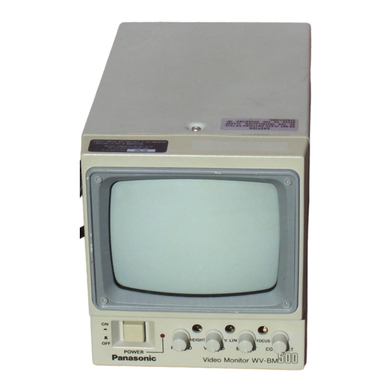
Page 5: Major Operating Controls And Their Functions
MAJOR OPERATING CONTROLS AND THEIR FUNCTIONS WV-BM500 <Front View> H.HOLD POWER 1. POWER ON/OFF SWITCH (POWER, ON/OFF) This is a push-push type switch which turns the power of this monitor on and off. Press once and the switch remains down (;) for turning on the power of monitor. - Page 6 3. HORIZONTAL HOLD [H-HOLD] This control is used to Lock in the picture horizon- tally. 4. HEIGHT [HEIGHT] Adjust the vertical height of the picture. 5. VERTICAL HOLD [V-HOLD] This control is used to Lock in the picture vertical- 6. Vertical Linearity (V-LIN) Adjust for vertical distortion of the picture.
- Page 7 WV-BM503 <Front View> <Rear View> • Model WV-BM503 combines three WV-BM500 video monitors. O P E N 5 0 3 Video Monitor WV-BM...
-
Page 8: Operating Procedure
17. RACK PANEL (WV-BM503) 18. FIXING SCREW for RACK PANEL (WV-BM503) 19. OPERATION COVER (WV -BM503) 20. PANEL KNOB and SCREW (WV-BM503) 21. RACK-MOUNT CHASSIS (WV-BM503) OPERATING PROCEDURE 1. Set the Power On/Off Switch (1) to the ON position. 2. Adjust the Brightness Control (7) and Contrast Control (9). -
Page 9: Installation
5. Height (4) This recessed screwdriver control should be adjusted simultaneously to give proper vertical height consistent with good vertical linearity. Adjustment should be made to extend the picture limits approximately 1/10” beyond the top and bot- tom edges of the mask at over scanning operation. 6. -
Page 10: Connections
CONNECTIONS Power Cable 1. Keep the camera Power switched OFF during installation. 2. Connect the Power Cord (16) to a 60 Hz grounded electrical outlet 120V AC . Video Cable 1. Use the RG-59/U (3C-2V), RG-6/U (5C-2V). RG- 11/U (7C-2V) or RG-15/U (10C-2V) coaxial cable. 2. -
Page 11: System Connections
Last Video Monitor Internal Sync Connection • Connect the Video Input Connector (11) on the monitor to the Video Out Terminal of cameras with WV-BM500 75-ohm coaxial cables. External Sync Connection • When a non-composite video signal is connected 120V... -
Page 12: Specifications
Weight and dimension indicated above are approximate. Specifications are subject to change without notice. 120V AC60Hz WV-BM500 Approx. 14W, WV-BM503 Approx. 42W 5” diagonal actual visual size 75Ω or high impedance (Auto Termination) 1.0 Vp-p composite (0.5 Vp-p - 2.0 Vp-p) More than 700 lines (Horizontal at center) Horizontal : 15.75k Hz... -
Page 13: Standard Accessories
STANDARD ACCESSORIES (Supplied) WV-BM503 • Fixing Screws for Rack Panel ... 2 pcs. (Part No. : YWL831-EM01A) • Fiber Washers ... 2 pcs. (Part No. : YWL1201ER01) -11-... - Page 14 Broadcast & Television Systems Company Division of Matsushita Electric Corporation of America CLOSED CIRCUIT VIDEO EQUIPMENT DIVISION Executive Office: One Panasonic Way, Secaucus, New Jersey 07094 Regional Offices: Northeast: 43 Hartz Way, Secaucus, NJ 07094 (201) 348-7303 Southeast: 1854 Shackleford Court, Suite 115, Norcross, CA 30003 (404) 717-6835...