Table of Contents
Advertisement
Condensing Gas Water Heater
Therm 8000 S
Installation and operating instructions
Read installation manual prior to installation of this unit!
Read user manual before putting this unit in operation!
Observe the warnings in the manuals!
The installation room must fulfill the ventilation requirements!
Installation by an authorised person only!
Advertisement
Table of Contents

Related Manuals for Bosch Therm 8000 S


Summary of Contents for Bosch Therm 8000 S
- Page 1 Condensing Gas Water Heater Therm 8000 S Installation and operating instructions Read installation manual prior to installation of this unit! Read user manual before putting this unit in operation! Observe the warnings in the manuals! The installation room must fulfill the ventilation requirements!
-
Page 2: Table Of Contents
2 | Index Index Installation of the exhaustion accessory and Safety information and symbology ....3 admission of air ..... .18 Key to symbols . -
Page 3: Safety Information And Symbology
Safety information and symbology | 3 authorised technician. Safety information and symbology If you smell combustion gases: ▶ Turn off the heater (page 11). 1.1 Key to symbols ▶ Open doors and windows. ▶ Notify a gas fitter. Warnings Installation, modifications Warnings in this document are framed and ▶... -
Page 4: Technical Characteristics And Dimensions
4 | Technical Characteristics and Dimensions Technical Characteristics and Dimensions 2.1 Declaration of conformity with relevant EEC • Modulating water valve: regulations – Cold water temperature sensor – Water flow sensor This appliance fulfills European directive requirements • Hot water temperature sensor 2009/142/EEC, 92/42/EEC, 2006/95/EEC, 2004/108/EEC •... -
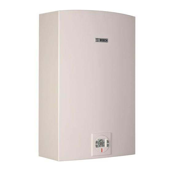
Page 5: Dimensions
Technical Characteristics and Dimensions | 5 2.6 Dimensions Fig. 1 [1] Front cover [2] Key pad [3] Cold water inlet: Ø ¾ “ [4] Gas connection: Ø ¾ “ [5] Hot water outlet: Ø ¾ “ [6] Support bracket [7] Condensate water drain Ø 32mm Therm 8000S 6 720 680 174 (2014/05) -
Page 6: Appliance Overview
6 | Technical Characteristics and Dimensions 2.7 Appliance overview 6720608948-06.1AL Fig. 2 [1] Air admission adaptor (not included) [10] Over heat prevention (temperature limiter) [2] Condensing Heat Exchanger [11] Observation window [3] Heat exchanger [12] Ignition electrodes [4] Primary fan (Mixer) [13] Backflow temperature sensor [5] Control unit [14] Ionization sensor... -
Page 7: Electrical Diagram
Technical Characteristics and Dimensions | 7 2.8 Electrical diagram T=90°C T=104°C T=110°C 6720608917-02.1AL Fig. 3 Electrical scheme [1] Intlet water temperature sensor [2] Outlet water temperature sensor [3] Backflow temperature sensor [4] Cascading output connection [5] Cascading input connection [6] Ionization sensor [7] Water flow sensor [8] Room sealed box temperature sensor [9] Heat exchanger overheat sensor (104 °C) -
Page 8: Technical Data
8 | Technical Characteristics and Dimensions 2.9 Technical data Technical characteristics Symbol Units GWHC 27 CTDE Power and flow Nominal useful power kW (Btu/h) 47,0 (160 370) Minimum useful power Pmin kW (Btu/h) 6,0 (20 475) Useful power (adjustment range) 6,0 - 47,0 Nominal thermal flow kW (Btu/h) -
Page 9: Operational Instructions
Regulation | 9 2.10 Operational instructions Hot water In this case, if the attempts to ignite go on too long, the security mechanisms prevent operation. Open the gas and water valves and ensure that all joints are hermetic. Security cut-off due to excessive water heating Place the principle switch (Fig. -
Page 10: Description Lcd Display
10 | Operating instructions 4.1 Description LCD Display CAUTION: Do not use any cleaning aggressive or corrosive agents to clean the window. Fig. 9 Flame indicator Fig. 5 Power bar indicator (input) Fig. 10 Solar mode indicator 6720608920-31 1AL Fig. 6 Temperature indicator Fig. -
Page 11: Connect And Disconnect The Appliance
Operating instructions | 11 ▶ Open water valve. ▶ Once the desired temperature is set, open the hot water tap. These appliance has an electronically Check for water leaks at all joints. controlled gas valve that modulates the burner input in response to both varying hot water flow rates and/or changes in any incoming and outgoing water temperatures. -
Page 12: Remote Control Operation (Accessory Nº 7 709 003 756)
12 | Operating instructions ▶ Test the remote control in front of the electronic box by NOTE: up to 6 remote controls can be simultaneously pressing the control keys. programmed for one single water heater, each with a range distance of 30m. CAUTION: remote control is not a toy - do not allow children to play with the remote control unit. -
Page 13: Program Button
Operating instructions | 13 4.8 Program button The appliance does not have a designated default priority. Priority is attributed when the first user selects a temperature Program button can be used/programmed in the appliance and (see chapter 4.4). in the remote control. The following symbol appears for other users The priority user may change the initial selection at any time. -
Page 14: Locked Condition
14 | Installation instructions 4.12 Locked condition This condition is only valid for appliances with one or more remote controls installed. Fig. 18 Error code After following instructions indicated in “Troubleshooting” 6720608920-33.1AL section, Fig. 20 Locked condition ▶ press reset button firmly in order to return heater to normal Whenever LCD shows the temperature setting cannot operation. -
Page 15: Important Remarks
Installation instructions | 15 5.1 Important remarks Surface Temperature The maximum surface temperature of the appliance is below ▶ Before installation, consult the gas company and current 85 °C. Special protection measures are not required for legislation regarding gas appliance and site ventilation. inflammable building materials or housings. -
Page 16: Installation
16 | Installation instructions ▶ Fix the fixing bracket to the wall using the screws and plugs ▶ Loosen the two Philips head screws located on bottom rear provided. of cover (Fig. 23). Fig. 23 Loosen the two screws ▶ Lift front cover panel upward and remove. 6720608913-05.1AL Fig. -
Page 17: Water Connection
Installation instructions | 17 5.7 Connecting the condensate water drain to the appliance CAUTION: ▶ Never rest the heater on the gas or water connections. For ease of installation it is recommended that the water be connected followed by the rest of the connections. -
Page 18: Gas Connection
18 | Installation instructions The condensate must be disposed of in accordance with local codes. 5.8 Gas connection DANGER: If local regulations are not follow exactly, a fire or explosion may result causing property damage, personal injury or loss of life. - Page 19 Installation instructions | 19 ▶ Tighten the 4 screws of the accessory of admission of air Fig. 29, [2]. 6720608920-24.1AL Fig. 29 Therm 8000S 6 720 680 174 (2014/05)
-
Page 20: Filling The Condensate Trap
20 | Installation instructions 5.9.2 Installation of the exhaustion accessory Ø 80mm ▶ Tighten the 3 screws of the concentric accessory. To install the accessory of the exhaustion accessory, proceed as follow; ▶ Put the gasket between the appliance and the accessory Fig. - Page 21 Installation instructions | 21 5.10.1Filling the condensate trap before vent pipe ▶ Fill the condensate trap by pouring approx.14 oz. (400ml) installation of water into the top of the drain tube. To avoid damage to the appliance use a funnel in this operation, see Fig. 34. ▶...
-
Page 22: Admission/Exhaustion Accessories
22 | Admission / exhaustion accessories (accessory Ø 80/125 mm) Admission / exhaustion accessories DANGER: Make sure that all flue connections are tighten sealed. (accessory Ø 80/125 mm) ▶ Failure to follow this requirement may cause dangerous exhaust gases to enter 6.1 Admission/exhaustion accessories (diameter living space which may result causing in mm) -
Page 23: Fitting Instructions
Admission / exhaustion accessories (accessory Ø 80/125 mm) | 23 6.2 Fitting instructions • The permissible maximum flue/air pipe length, Lmax, for the various possible flue configurations is specified in the tables starting on chapter 8.6. • If the concentric flue/air pipe enters a chimney below ground level, the appliance may register a fault and shut down in cold weather due to ice formation. -
Page 24: Approved Flue Systems
24 | Admission / exhaustion accessories (accessory Ø 80/125 mm) 6.4 Approved flue systems 6.4.1 Exhaustion type A Outdoor installation with accessory nº 7 709 003 732 Fig. 39 Ref. Description Minimum distance Installation next to window; Installation next to door; Installation near of any open for air >... - Page 25 Admission / exhaustion accessories (accessory Ø 80/125 mm) | 25 6.4.2 Exhaustion type B Ø 135 mm est. Ø 80 mm Ø 80 mm Ø 80 / 125 mm Ø 80 mm Ø 80 mm 6720608948-11.1AL 6720608920-36.1AL Fig. 40 6.4.3 Exhaustion type C Ø...
- Page 26 26 | Admission / exhaustion accessories (accessory Ø 80/125 mm) 6.4.4 Exhaustion type C Ø 135 mm est. Ø 80 / 125 mm ³ 6720608948-10.1AL ³ Fig. 42 6.4.5 Exhaustion type C Ø 80 mm 6720608920-28.1AL Fig. 43 6 720 680 174 (2014/05) Therm 8000S...
-
Page 27: Electrical Connection
Electrical connection | 27 6.4.6 Exhaustion type C Ø 135 mm est. Ø 80 / 125 mm Ø 80 mm Ø 80 mm 6720608920-29.1AL Fig. 44 7.1 Connection Electrical connection The electrical connection should be according to current regulations regarding DANGER: Risk of electric shock! domestic electrical installations. -
Page 28: Position Of The Fuses In Control Unit
28 | Installation instructions ▶ Check the fuses in the printed circuit board, see Fig. 47, [3]. 6720608913-09.1AL Fig. 45 Power cable connections 7.3 Position of the fuses in control unit To check fuses, proceed as follows; ▶ Remove the front cover, see Fig. 23. 6720608158-78.1AL ▶... -
Page 29: Measuring Gas Pressure
Installation instructions | 29 ▶ Press and hold "Program" button and press ON/OFF button DANGER: to turn appliance ON (Fig. 49 ). ▶ The following operations must be carried out by a qualified technician. 8.2 Measuring gas pressure Confirm gas pressure after installation. Connecting manometer ▶... - Page 30 30 | Installation instructions Measuring CO (Combustion cover Installed): CAUTION: ▶ Open all hot water taps to achieve a flow rate of at least 15 l/ One factor that may affect CO levels is m (1 tub and 2 sinks should be sufficient). If heater display improper gas pressure.
- Page 31 Installation instructions | 31 ▶ Verify CO readings in P2 mode. ▶ Repeat steps 1 and 2 as necessary until CO values are within the specified ranges. As soon as the levels of CO are correct, verify the values of CO corresponds to the limits of the Table 11 .
-
Page 32: Program Values
32 | Installation instructions 8.4 Program values CAUTION: Misadjusted program values This section describes details on programming the appliance. can lead to appliance malfunction, errors, For most applications the factory default values will provide and service calls. robust and stable operation. Program Description Factory default... -
Page 33: Control Board Diagnostics
Installation instructions | 33 8.5 Control board diagnostics Diagnostic menu To access the diagnostic menu, proceed as follow: 3rd most recent error ▶ Press ON/OFF button to turn off the appliance. 4th most recent error ▶ Press and hold "Program" button and press ON/OFF 5th most recent error button to turn appliance ON. - Page 34 34 | Installation instructions Before adjusting the fan speed it is necessary to verify the Exhaust admission / exhaustion system, calculating the total length of Straight section length ___ x 1 = ________ the exhaust pipes and quantity of elbows. 90°...
- Page 35 Installation instructions | 35 Example table: Intake Straight section length _4_ x 1= Concentric conducts 90° elbows (qty) _1_ x 1 = Straight section length 5 x 1 = 45° elbows (qty) _0_ x 0.5 = 90° elbow (qty) _1_ x 2 = 30°...
- Page 36 36 | Installation instructions Fan speed for separate tubes Ø80/80 mm Mode Conduct length Fan speed From 1 m until 6 m from 6.1 m until 14m from 14.1m until 16 m Table 23 1) Total conducts lengths of Table 18 . Do not count with the first elbow and the accessory of wind/rain protection.
-
Page 37: Maintenance
▶ Your appliance must only be serviced by a Bosch Technical Assistance delegate. ▶ Use only genuine accessories. ▶ Verify CO levels (see chapter 8.3) and correct it if... -
Page 38: Verify The Fuses In The Control Board
38 | Maintenance 9.2 Verify the fuses in the control board To check fuses, proceed as follows; ▶ Remove the front cover, see Fig. 23. ▶ Remove the three screws from the control unit (Fig. 56 and Fig. 57, [2]). 6720608920-38.1Av Fig. - Page 39 Maintenance | 39 ▶ Remove the clip and disconnect the drain tube, see Fig. 61. It is mandatory to propely replace the gaskets and o-rings. ▶ Assemble the condensate unit and all other parts in reverse order of disassembly. 9.3.1 Cleaning the condensate trap WARNING: Material damage! ▶...
-
Page 40: Startup After Maintenance
40 | Maintenance ▶ Check water level in the condensate trap (see Fig. 63 ). Fig. 63 ▶ After filling reassemble all parts in reverse order. 9.4 Startup after maintenance ▶ Check all water and gas joints. ▶ Read chapter 4 "Operating instructions" and/or chapter 8 "Installation instructions". -
Page 41: Problem Solving
Problem solving | 41 10 Problem solving 10.1 Problem/Cause/Solution To remove error code from the display, press the reset button. Display Cause Solution Fault in the flue gas limiter. 1. Check continuity of the flue gas limiter (normally closed). Temperature above 110 °C 2. - Page 42 42 | Problem solving Display Cause Solution (Flashing) Outlet temperature sensor not 1. Check that the sensor is firmly attached to the vertical section of the sensing expected output hot water pipe. temperature. (Status message, 2. Ensure that hot water sensor is not placed on any bends in the hot not an error) water pipe or misreading may occur.
- Page 43 Problem solving | 43 Display Cause Solution Hot water temperature sensor 1. Check the correct position and fixation of the NTC sensor. (NTC) at the exit of the 2. Check the electric connections and connectors of the hot water appliance detect a high temperature sensor.
- Page 44 44 | Problem solving Display Cause Solution No flame ionization detected 1. Verify that all manual gas shut off valves are open. with water flow. 2. Check gas type. 3. Check gas pressure. 4. Reset error code and open a water tap to cycle the heater in an effort to purge air.
-
Page 45: Functional Scheme
Functional scheme | 45 11 Functional scheme IDLE Water flow > 0.5 gpm water tap See error code table (> 1.9 l/min) open? (see WF calc.) Fan speed = correct Ionization = off Appliance Temp. limiter = closed ready to start? Temp. -
Page 46: Environmental Protection
46 | Environmental protection 12 Environmental protection Environmental protection is a basic strategy of our company. The quality of our products, profitability and environmental protection are equal-ranking goals for us. Laws and regulations concerning environmental protection are strictly observed. We use the best possible technology and materials, under economic considerations, to protect the environment. -
Page 47: Warranty Terms
1685 Midrand South Africa Tel: +27 (0)11 651 9600 Bosch Gas Water Heaters have been thoroughly tested at the factory and fulfills all standards valid in the country. Robert Bosch (Pty) Ltd. provides warranty for this model and its components, for the period of 24 months from the date of the... - Page 48 6720680174 Bosch Thermotechnology South Africa Robert Bosch Pty (Ltd) 15th Road, Randjiespark 1685 Midrand SOUTH AFRICA...