Table of Contents
Advertisement
Quick Links
DVD-Video Recorder
Contents
1
2
3
4
5
6
Block Diagrams, Waveforms, Wiring Diagram
7
Servo Board 43015: Processor
Servo Board 43015: Dec./Encoder
Servo Board 43015: Power
Servo Board 43353: Processor
Servo Board 43353: Dec./Encoder
Servo Board 43353: Power
Servo Board 43661: Processor
Servo Board 43661: Dec./Encoder
8
9
Circuit-, IC Descriptions and List
of Abbreviations
©
Copyright 2003 Philips Consumer Electronics B.V. Eindhoven, The Netherlands.
All rights reserved. No part of this publication may be reproduced, stored in a
retrieval system or transmitted, in any form or by any means, electronic,
mechanical, photocopying, or otherwise without the prior permission of Philips.
Published by GH03 0395 Service PaCE
Page
2
3
5
6
15
15
16
17
Diagram PWB
18
23-24
(Diagram 1)
)
19
23-24
20
23-24
(Diagram 3)
21
23-24
(Diagram 4)
22
23-24
(Diagram 5)
25
30-31
(Diagram 1)
26
30-31
(Diagram 2)
27
30-31
(Diagram 3)
28
30-31
(Diagram 4)
29
30-31
(Diagram 5)
32
37-38
(Diagram 1)
33
37-38
(Diagram 2)
34
37-38
(Diagram 3)
35
37-38
(Diagram 4)
36
37-38
(Diagram 5)
39
39
46
51
Printed in the Netherlands
DVD+RW Basic Engine
Contents
Subject to modification
VAE8015
VAE8020
Page
EN 3122 785 12473
Advertisement
Table of Contents

Related Manuals for Philips VAE8015


Summary of Contents for Philips VAE8015
-
Page 1: Table Of Contents
All rights reserved. No part of this publication may be reproduced, stored in a retrieval system or transmitted, in any form or by any means, electronic, mechanical, photocopying, or otherwise without the prior permission of Philips. Published by GH03 0395 Service PaCE... -
Page 2: Technical Specifications
EN 2 VAE8015 / 8020 Technical Specifications 1. Technical Specifications VAE8015/VAE8020 functionality: • Loading of 8 cm and 12 cm discs by a motorized tray • Disc type recognition and in case of a DVD+RW disc laser power calibration •... -
Page 3: Safety Instructions, Warnings And Notes
Safety Instructions, Warnings and Notes VAE8015 / 8020 EN 3 2. Safety Instructions, Warnings and Notes Safety Instructions Warnings 2.1.1 General Safety 2.2.1 General Safety regulations require that during a repair: • All ICs and many other semiconductors are susceptible to electrostatic discharges (ESD, symbol ). - Page 4 EN 4 VAE8015 / 8020 Safety Instructions, Warnings and Notes Notes Table 2-1 Configuration matrix - Basic Engines VAE 8015 and VAE 8020...
-
Page 5: Directions For Use (No Dfu Necessary)
Directions For Use VAE8015 / 8020 EN 5 Directions For Use Not applicable... -
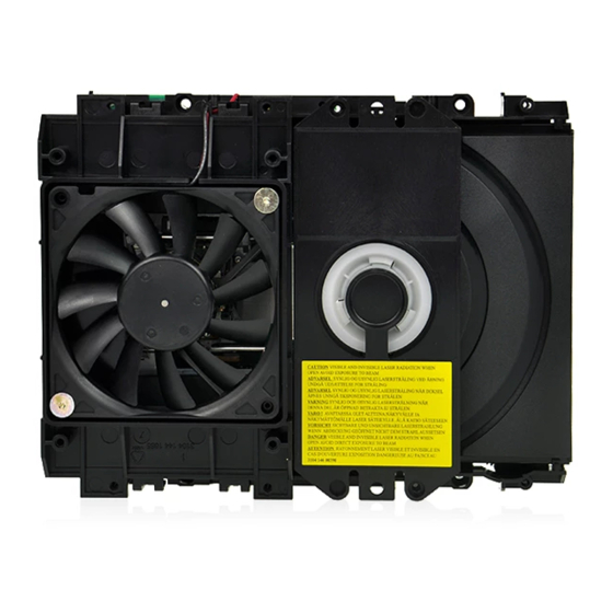
Page 6: Mechanical Instructions
EN 6 VAE8015 / 8020 Mechanical Instructions 4. Mechanical Instructions Index of this chapter: 4.2.2 1. General 2. Disassembly 1. Flip the module180 degrees, so you can access the PWB. 3. Re-assembly 2. Disconnect the four flex foils from the PWB connectors (1100, 1300, 1302, and 1303) at the component side. - Page 7 Mechanical Instructions VAE8015 / 8020 EN 7 4.2.4 Sledge-motor Assy Caution: Never try to align the DVD-Module! ! ! Only the factory can do this properly. Service engineers are only allowed to exchange the sledge motor assy. CL 26532126_014.eps 191102 Figure 4-3 Sledge-motor assy 1.
-
Page 8: Service Modes, Error Codes And Fault Finding
EN 8 VAE8015 / 8020 Service Modes, Error Codes and Fault Finding 5. Service Modes, Error Codes and Fault Finding Index of this chapter: 5.2.2 Oscillator Check 1. General 2. Start-up Measurements Table 5-3 Table of clock signals. 3. Diagnostic Software 4. - Page 9 Service Modes, Error Codes and Fault Finding VAE8015 / 8020 EN 9 Error handling Table 5-4 Nuclei overview Basic Engine Empress Each nucleus returns an error code. This code contains six Digiboard numerals, which means: Ref. # Function name Description...
- Page 10 EN 10 VAE8015 / 8020 Service Modes, Error Codes and Fault Finding If pressing 'M' has made a choice for Menu Interface, the Main Ref. # Function name Description Menu will appear. DS_BE_GetSelfTest It retrieves the result of the Result...
- Page 11 Service Modes, Error Codes and Fault Finding VAE8015 / 8020 EN 11 Fault Finding Below you will find faultfinding trees for all the main parts of the Basic Engine. 5.4.1 Basic Engine BASIC ENGINE FUNCTIONAL TEST Basic Engine Check Basic Engine S2B Echo...
- Page 12 EN 12 VAE8015 / 8020 Service Modes, Error Codes and Fault Finding 5.4.2 Loader Loader Checking Basic Engine Loader Check -Check wire soldering on tray motor -Check tray motor wire connector Tray is not Opening/Closing -Check tray mechanical Command: 615/616...
- Page 13 Service Modes, Error Codes and Fault Finding VAE8015 / 8020 EN 13 5.4.4 PCB Checking Check: Basic Engine PCB Check -MACE wrong -7306 burned -7302 burned Communication -S2B connector -7000 bad soldering -power connector -2209 missing -2210 missing -MACE wrong...
- Page 14 EN 14 VAE8015 / 8020 Service Modes, Error Codes and Fault Finding Personal Notes:...
-
Page 15: Block Diagram
Block Diagram. VAE8015 / 8020 6. Block Diagram. Block Diagram LOADER FS diode laser 650nm OPU64 Tray Sense Actuator Tilt Motor Disc Motor 780nm LDGU+OPIC 650nm PD TZA1030 Tray Motor TZA1032 TZA1030 Sledge RADIAL LADIC DROPPI FOCUS EEprom tilt sensor... -
Page 16: Testpoint Overview Servo Board 43015
Block Diagram. VAE8015 / 8020 Test Point Overview Servo Board 43015 F001 A1 F409 A3 I220 A3 I309 B2 I407 B4 F101 B3 F410 B4 I221 A3 I310 C2 I408 B3 F102 B3 F411 B4 I223 A4 I311 B2 I409 B3... -
Page 17: Testpoint Overview Servo Board 43353
Block Diagram. VAE8015 / 8020 Test Point Overview Servo Board 43353 F001 A1 F323 A2 I204 A4 I296 A3 I372 C1 I474 B4 F002 A1 F400 B4 I205 A4 I297 A2 I373 B3 I475 A2 D3V3S Clock Mace3 A3V3A PSEN-P... -
Page 18: Electrical Diagrams And Print-Layouts
Electrical Diagrams and Print-Layouts VAE8015 / 8020 7. Electrical Diagrams and Print-Layouts Servo Board 123 43015: Pre- Processor 1100 A2 2100 B11 2102 B11 2104 D12 2105 D12 2106 D12 2110 H11 PRE-PROCESSOR 2111 C2 2116 F5 2121 D9 2122 E12... -
Page 19: Servo Board 43015: Mace3
Electrical Diagrams and Print-Layouts VAE8015 / 8020 Servo Board 123 43015: MACE3 U1 K2 U2 K2 U3 K2 U4 K2 U5 K2 U6 N2 MACE3 1200 B1 DA(0:7) 1201 G6 1202 F1 1203 G19 2200 B12 2202 C15 2203 D15... -
Page 20: Servo Board 43015: Driver
Electrical Diagrams and Print-Layouts VAE8015 / 8020 Servo Board 123 43015: Driver 1300 A1 7304-B F3 1301 E7 7306 F8 1302 E1 7308 H4 1303-1 G1 7309 H5 1303-2 G1 7310 I4 2302 1303-3 G1 7311 I2 3305 DRIVER 1303-4 H1... - Page 21 Electrical Diagrams and Print-Layouts VAE8015 / 8020 Servo Board 123 43015: Decoder / Encoder 1401 G1 F416 G9 1402 E14 F417 G9 2400 B5 F418 D2 2401 B5 F425 F12 2402 C13 F426 B1 5402 D3V3dec D3V3 D3V3dec 2403 C13...
- Page 22 Electrical Diagrams and Print-Layouts VAE8015 / 8020 Servo Board 123 43015: Power 1000 C2 1500 H2 1501 H3 2002 E6 2003 E7 2004 E7 2005 E7 POWER 2008 G7 2009 G7 2010 E9 2011 E9 2012 E9 2013 E10 2014 F8...
- Page 23 Electrical Diagrams and Print-Layouts VAE8015 / 8020 Layout Servo Board (Top Side) 123 43015 1000 A4 4400 A2 1301 C4 5202 A2 1304 B4 5203 A2 1402 B1 7201 A1 2116 A3 7202 A1 2125 B2 7206 A2 2202 A1...
- Page 24 Electrical Diagrams and Print-Layouts VAE8015 / 8020 Layout Servo Board (Bottom Side) 123 43015 1100 B3 2327 B3 3227 A3 3348 A2 7205 A3 1200 A2 2328 B3 3231 A4 3351 B2 7301 C2 1201 A2 2329 A2 3235 A4...
- Page 25 Electrical Diagrams and Print-Layouts VAE8015 / 8020 Servo Board 123 43353: Pre- Processor 1100 A2 2100 B10 2101 C9 2102 B11 2104 D12 2105 D12 2106 D12 PRE-PROCESSOR 2110 H11 2111 C2 2116 F4 2121 D9 2122 E12 2125 C12...
-
Page 26: Servo Board 43353: Mace3
Electrical Diagrams and Print-Layouts VAE8015 / 8020 Servo Board 123 43353: MACE3 1200 B1 1201 G5 1202 F1 1203 G18 2200 B11 2202 C15 2203 D15 MACE3 2207 E5 DA(0:7) 2208 E10 2209 I6 2210 I6 2211 H16 2212 J6... -
Page 27: Servo Board 43353: Driver
Electrical Diagrams and Print-Layouts VAE8015 / 8020 Servo Board 123 43353: Driver 1300 A1 7304-B F3 1301 E7 7306 F8 1302 E1 7308 H4 1303-1 G1 7309 H5 1303-2 G1 7310 I4 1303-3 G1 7311 I2 2302 3305 1303-4 H1... - Page 28 Electrical Diagrams and Print-Layouts VAE8015 / 8020 Servo Board 123 43353: Decoder / Encoder 1401 G1 F425 F12 1402 E14 F426 B1 2400 B5 2401 B5 5401 2402 A8 D3V3dec D3V3dec 2405 A11 100MHZ 2406 D2 DECODER / ENCODER 2407 D2...
- Page 29 Electrical Diagrams and Print-Layouts VAE8015 / 8020 Servo Board 123 43353: Power 1000 C2 1500 H2 1501 H3 2002 D6 2003 D7 2004 D7 2005 D7 POWER 2008 G7 2009 G7 2010 D9 2011 D9 2012 D9 2013 D10 2014 F8...
- Page 30 Electrical Diagrams and Print-Layouts VAE8015 / 8020 Layout Servo Board 123 43353 (Top Side) 1000 A4 4400 A2 1301 C4 5202 A2 1304 B4 5401 B1 1402 B1 7201 A1 2116 A3 7202 A1 2125 B2 7401 B1 2202 A1...
- Page 31 Electrical Diagrams and Print-Layouts VAE8015 / 8020 Layout Servo Board 123 43353 (Bottom Side) 1100 B3 2326 B3 3238 A2 3355 C1 7312 C1 1200 A2 2327 B3 3241 A3 3356 C1 7402 B4 1201 A2 2328 B3 3244 A3...
- Page 32 Electrical Diagrams and Print-Layouts VAE8015 / 8020 Servo Board 123 43661: Pre- Processor 1100 A2 2100 B10 2101 C9 2102 B11 2104 D12 2105 D12 PRE-PROCESSOR 2106 D12 2110 H11 2111 C2 2116 F4 2121 D9 2122 E12 2125 C12...
-
Page 33: Servo Board 43661: Mace3
Electrical Diagrams and Print-Layouts VAE8015 / 8020 Servo Board 123 43661: MACE3 1200 B1 1201 G5 1202 F1 1203 G18 2200 B11 2202 C15 2203 D15 2207 E5 MACE3 DA(0:7) 2208 E10 2209 I6 2210 I6 2211 H16 2212 J6... -
Page 34: Servo Board 43661: Driver
Electrical Diagrams and Print-Layouts VAE8015 / 8020 Servo Board 123 43661: Driver 1300 A1 7304-B F3 1301 E7 7306 F8 1302 E1 7308 H4 1303-1 G1 7309 H5 DRIVER 1303-2 G1 7310 I4 1303-3 G1 7311 I2 2302 3305 1303-4 H1... - Page 35 Electrical Diagrams and Print-Layouts VAE8015 / 8020 Servo Board 123 43661: Decoder/Encoder 1401 G1 F404 H2 1402 E14 F405 G2 2400 B5 F406 D8 2401 B5 F407 D8 DECODER / ENCODER 2402 B11 F409 B1 2405 A11 F410 D8 D3V3dec...
-
Page 36: Servo Board 43661: Power
Electrical Diagrams and Print-Layouts VAE8015 / 8020 Servo Board 123 43661: Power 1000 C2 1500 H2 1501 H3 POWER 2002 E6 2003 E7 2004 E7 2005 E7 2008 G7 2009 G7 2010 E9 2011 E9 2012 E9 2013 E10 2014 F8... - Page 37 Electrical Diagrams and Print-Layouts VAE8015 / 8020 Layout Servo Board 123 43661 (Top Side) TR 13007_001 150706...
- Page 38 Electrical Diagrams and Print-Layouts VAE8015 / 8020 Layout Servo Board 123 43661 (Bottom Side) TR 13006_001 150703...
-
Page 39: Alignments (No Alignments Necessary)
Alignments VAE8015 / 8020 EN 39 8. Alignments No alignments necessary 9. Circuit Descriptions, Abbreviation List, and Data Sheets Index of this chapter: The PWB is a high tech module (multi layer, full SMC) with very 1. Introduction high component density. Despite of this, it is designed in such 2. - Page 40 EN 40 VAE8015 / 8020 Circuit Descriptions, Abbreviation List, and Data Sheets This section describes briefly the functional behaviour of the The DVD-M has an optical pickup unit (OPU) consisting of two engine. It performs all basic servo functions: lasers, one for CD with a wavelength of 780 nm, and one for •...
- Page 41 Circuit Descriptions, Abbreviation List, and Data Sheets VAE8015 / 8020 EN 41 9.4.2 LADIC Some features of the SPIDRE: • A “Writer add-on”. The LADIC (Laser Driver IC, type number TZA1032) fulfils • Double-Writer prepared (both CDR/RW and DVDRW). three main functions: •...
- Page 42 EN 42 VAE8015 / 8020 Circuit Descriptions, Abbreviation List, and Data Sheets reads three analogue signals (A1, A2 and CALF), representing The demodulator part detects the frame synchronisation Max, Min, and Average values of the EFM signal respectively. signals and decodes the EFM (14 bit) and EFM+ (16 bit) data It also takes the Power (PW) signal from the laser controller and sub-code words into 8-bit symbols.
- Page 43 Circuit Descriptions, Abbreviation List, and Data Sheets VAE8015 / 8020 EN 43 All recordable DVD media types feature a microscopic wobble program will receive a reset, and the data of the Flash ROM is groove embedded in the plastic substrate. This wobble copied into the uP-RAM.
- Page 44 EN 44 VAE8015 / 8020 Circuit Descriptions, Abbreviation List, and Data Sheets Abbreviation list Microprocessor Video CD Luminance (Y) and Chrominance (C) Analogue to Digital Converter signal ADIP ADdress In Pre-groove Component video Automatic Gain Control Compact Disc Constant Linear Velocity...
- Page 45 Circuit Descriptions, Abbreviation List, and Data Sheets VAE8015 / 8020 EN 45 IC Data Sheets In this paragraph, the internal block diagrams and pinning are given of ICs that are drawn as a 'black box' in the electrical diagrams (with the exception of 'memory' and 'logic' ICs).
- Page 46 10. Spare Parts List 10.1 Exploded Views Basic Engine...
- Page 47 Loader...
- Page 48 DVD-M CL 26532126_044.eps 181202...
-
Page 49: Electrical Parts List
Spare Parts List VAE8015 / 8020 EN 49 2101 5322 126 11583 10nF 10% 50V 0603 2434 4822 122 33741 10pF 10% 50V Miscellaneous 2102 2238 586 59812 0603 50V 100NP80M 2435 4822 122 33761 22pF 5% 50V 2104 5322 126 11583 10nF 10% 50V 0603... - Page 50 EN 50 VAE8015 / 8020 Spare Parts List 3315 4822 051 20108 1Ω 5% 0.1W 5202 2422 549 43769 IND FXD SM EMI 100mH z 3316 4822 051 20228 2Ω2 5% 0.1W 30R R 3317 4822 051 20228 2Ω2 5% 0.1W...
-
Page 51: Revision List
Revision List VAE8015 / 8020 EN 51 11. Revision List 11.1 3122 785 12471 • December 12 2002 1. New partslist added in chapter 10 11.2 3122 785 12472 • December 20 2002 1. Configuration matrix table added in chapter 2 2. - Page 52 EN 52 VAE8015 / 8020 Revision List...