
Related Manuals for Motorola Spectra


Summary of Contents for Motorola Spectra
- Page 1 Spectra ® /Spectra ® 9000 900 MHz Two-W ay FM Radios 4, 12, and 30 W atts RF Power Service Manual 68P81074C40-O...
-
Page 2: Table Of Contents
VI. EDIT ZONE SCAN LISTS ..............................20 VII. CHANGE PARAMETERS ASSOCIATED WITH A MODE (See Figure 9.).................20 , Motorola, Spectra, HearClear, Privacy Plus, SECURENET, Touch-Code, Single Tone, SMARTNET, Private Conversation, Call Alert, Channel Scan, MDC-1200, Systems 9000, Private-Line, and Digital Private-Line are trademarks of Motorola. - Page 3 FEATURE MATRIX FOR SPECTRA 900 MHz CONVENTIONAL RADIOS “AK”, “BK”, “CK” SUFFIXED MODELS ....77 FEATURE MATRIX FOR SPECTRA 900 MHz PRIVACY PLUS RADIOS “AK” AND “CK” SUFFIXED MODELS ....78 FEATURE MATRIX FOR SPECTRA 900 MHz PRIVACY PLUS RADIOS “CK” AND “DK” SUFFIXED MODELS ....79 FEATURE MATRIX FOR SPECTRA 900 MHz SMARTNET RADIOS “AK”, “BK”, “CK”...
- Page 4 Figure 18 Removing Memory Board ........................44 Figure 19 Spectra Control Head Self-Test ......................50 Figure 20 Spectra 9000 Control Head Self-Test ....................51 Figure 21 Front Panel Diagnostics; Key Closure Displays..................52 Figure 21A Front Panel Diagnostics; Rotary Key Closure Displays ..............52 Figure 22 Front Panel Diagnostics;...
-
Page 5: Performance Specifications For Spectra Conventional 4 Watt And 30 Watt Radios
PERFORMANCE SPECIFICATIONS FOR SPECTRA CONVENTIONAL 4 WATT AND 30 WATT RADIOS GENERAL Channel Capability 128 Conventional 900MHz frequencies (A4 Model) 128 Conventional 900MHz frequencies (A5 Model) 128 Conventional 900MHz frequencies (A7 Model) Primary Power 12Vdc negative ground only Dimensions 2.0" H x 7.1" W x 8.6" L Weight 5.5 lbs. -
Page 6: Performance Specifications For Spectra Privacy Plus
PERFORMANCE SPECIFICATIONS FOR SPECTRA PRIVACY PLUS TRUNKED/CONVENTIONAL 900 MHz RADIO... -
Page 7: Performance Specifications For Spectra Smartnet
PERFORMANCE SPECIFICATIONS FOR SPECTRA SMARTNET TRUNKED/CONVENTIONAL 900 MHz RADIO... -
Page 8: Performance Specifications For Spectra 9000 Radios (900 Mhz, 30 Watts)
PERFORMANCE SPECIFICATIONS FOR SPECTRA 9000 RADIOS (900 MHz, 30 WATTS) -
Page 9: Performance Specifications For Spectra 9000 Control Unit And Speaker
PERFORMANCE SPECIFICATIONS FOR SPECTRA 9000 CONTROL UNIT AND SPEAKER CONTROL UNIT Dimensions (excluding 6.5" W x 3.375" H x 1.687" D mounting bracket) (166 mm x 87 mm x 42 mm) Weight 1 lb. (465 g) Current Drain 300 mA... -
Page 10: Model Chart For Spectra 900 Mhz Two-Way Mobile Fm Radios
MODEL CHART FOR SPECTRA 900 MHz TWO-WAY MOBILE FM RADIOS (Listed are current-suffixed models only; previous suffixed models are listed in Appendix) @ @ @ @ @ @ @ @ @ @ @ @ @ @ @ @ @ @ @ @ @ @ @ @ @ @ @ @ @ @ @ @ @ @ @ @ @ @ @ @ @ @ @ @ @ @ @ @ @ @ @ @ @ @ @ @ @ @ @ @ @ @ @ @ @ @ @ @ @ @ @ @ @ @ @ @ @ @ @ @ @ @ @ @ @ @ @ @ @ @ @ @ @ @ @ @ @ @ @ @ @ @ @ @ @ @ @ @ @ @ @ @ @ @ @ @ @ @ @ @ @ @ @ @ @ @ @ @ @ @ @ @ @ @ @ @ @ @ @ @ @ @ @ @ @ @ @ @ @ @ @ @ @ @ @ @ @ @ @ @ @ @ @ @ @ @ @ @ @ @ @ @ @ @ @ @ @ @ @ @ @ @ @ @ @ @ @ @ @ @ @ @ @ @ @ @ @ @ @ @ @ @ @ @ @ @ @ @ @ @ @ @ @ @ @ @ @ @ @ @ @ @ @ @ @ @ @ @ @ @ @ @ @ @ @ @ @ @ @ @ @ @ @ @ @ @ @ @ @ @ @ @ @ @ @ @ @ @ @ @ @ @ @ @ @ @ @ @ @ @ @ @ @ @ @ @ @ @ @ @ @ @ @ @ @ @ @ @ @ @ @ @ @ @ @ @ @ @ @ @ @ @ @ @ @ @ @ @ @ @ @ @ @ @ @ @ @ @ @ @ @ @ @ @ @ @ @ @ @ @ @ @ @ @ @ @ @ @ @ @ @ @ @ @ @ @ @ @ @ @ @ @ @ @ @ @ @ @ @ @ @ @ @ @ @ @ @ @ @ @ @ @ @ @ @ @ @ @ @ @ @ @ @ @ @ @ @ @ @ @ @ @ @ @ @ @ @ @ @ @ @ @ @ @ @ @ @ ? h... -
Page 11: Model Chart For Spectra 900 Mhz Control Head Button Kits (All Package Models)
MODEL CHART FOR SPECTRA 900 MHz CONTROL HEAD BUTTON KITS (All Package Models) @ @ @ @ @ @ @ @ @ @ @ @ @ @ @ @ @ @ @ @ @ @ @ @ @ @ @ @ @ @ @ @ @ @ @ @ @ @ @ @ @ @ @ @ @ @ @ @ @ @ @ @ @ @ @ @ @ @ @ @ @ @ @ @ @ @ @ @ @ @ @ @ @ @ @ @ @ @ @ @ @ @ @ @ @ @ @ @ @ @ @ @ @ @ @ @ @ @ @ @ @ @ @ @ @ @ @ @ @ @ @ @ @ @ @ @ @ @ @ @ @ @ @ @ @ @ @ @ @ @ @ @ @ @ @ @ @ @ @ @ @ @ @ @ @ @ @ @ @ @ @ @ @ @ @ @ @ @ @ @ @ @ @ @ @ @ @ @ @ @ @ @ @ @ @ @ @ @ @ @ @ @ @ @ @ @ @ @ @ @ @ @ @ @ @ @ @ @ @ @ @ @ @ @ @ @ @ @ @ @ @ @ @ @ @ @ @ @ @ @ @ @ @ @ @ @ @ @ @ @ @ @ @ @ @ @ @ @ @ @ @ @ @ @ @ @ @ @ @ @ @ @ @ @ @ @ @ @ @ @ @ @ @ @ @ @ @ @ @ @ @ @ @ @ @ @ @ @ @ @ @ @ @ @ @ @ @ @ @ @ @ @ @ @ @ @ @ @ @ @ @ @ @ @ @ @ @ @ @ @ @ @ @ @ @ @ @ @ @ @ @ @ @ @ @ @ @ @ @ @ @ @ @ @ @ @ @ @ @ @ @ @ @ @ @ @ @ @ @ @ @ @ @ @ @ @ @ @ @ @ @ @ @ @ @ @ @ @ @ @ @ @ @ @ @ @ @ @ @ @ @ @ @ @ @ @ @ @ @ @ @ @ @ @ @ @... - Page 12 MODEL CHART FOR SPECTRA 9000 TWO-WAY RADIO 900 MHz, 30 WATTS RF POWER @ @ @ @ @ @ @ @ @ @ @ @ @ @ @ @ @ @ @ @ @ @ @ @ @ @ @ @ @ @ @ @ @ @ @ @ @ @ @ @ @ @ @ @ @ @ @ @ @ @ @ @ @ @ @ @ @ @ @ @ @ @ @ @ @ @ @ @ @ @ @ @ @ @ @ @ @ @ @ @ @ @ @ @ @ @ @ @ @ @ @ @ @ @ @ @ @ @ @ @ @ @ @ @ @ @ @ @ @ @ @ @ @ @ @ @ @ @ @ @ @ @ @ @ @ @ @ @ @ @ @ @ @ @ @ @ @ @ @ @ @ @ @ @ @ @ @ @ @ @ @ @ @ @ @ @ @ @ @ @ @ @ @ @ @ @ @ @ @ @ @ @ @ @ @ @ @ @ @ @ @ @ @ @ @ @ @ @ @ @ @ @ @ @ @ @ @ @ @ @ @ @ @ @ @ @ @ @ @ @ @ @ @ @ @ @ @ @ @ @ @ @ @ @ @ @ @ @ @ @ @ @ @ @ @ @ @ @ @ @ @ @ @ @ @ @ @ @ @ @ @ @ @ @ @ @ @ @ @ @ @ @ @ @ @ @ @ @ @ @ @ @ @ @ @ @ @ @ @ @ @ @ @ @ @ @ @ @ @ @ @ @ @ @ @ @ @ @ @ @ @ @ @ @ @ @ @ @ @ @ @ @ @ @ @ @ @ @ @ @ @ @ @ @ @ @ @ @ @ @ @ @ f...
-
Page 13: Model Chart For Spectra 9000 Control Unit Button Kits (All Package Models)
MODEL CHART FOR SPECTRA 9000 CONTROL UNIT BUTTON KITS (All Package Models) @ @ @ @ @ @ @ @ @ @ @ @ @ @ @ @ @ @ @ @ @ @ @ @ @ @ @ @ @ @ @ @ @ @ @ @ @ @ @ @ @ @ @ @ @ @ @ @ @ @ @ @ @ @ @ @ @ @ @ @ @ @ @ @ @ @ @ @ @ @ @ @ @ @ @ @ @ @ @ @ @ @ @ @ @ @ @ @ @ @ @ @ @ @ @ @ @ @ @ @ @ @ @ @ @ @ @ @ @ @ @ @ @ @ @ @ @ @ @ @ @ @ @ @ @ @ @ @ @ @ @ @ @ @ @ @ @ @ @ @ @ @ @ @ @ @ @ @ @ @ @ @ @ @ @ @ @ @ @ @ @ @ @ @ @ @ @ @ @ @ @ @ @ @ @ @ @ @ @ @ @ @ @ @ @ @ @ @ @ @ @ @ @ @ @ @ @ @ @ @ @ @ @ @ @ @ @ @ @ @ @ @ @ @ @ @ @ @ @ @ @ @ @ @ @ @ @ @ @ @ @ @ @ @ @ @ @ @ @ @ @ @ @ @ @ @ @ @ @ @ @ @ @ @ @ @ @ @ @ @ @ @ @ @ @ @ @ @ @ @ @ @ @ @ @ @ @ @ @ @ @ @ @ @ @ @ @ @ @ @ @ @ @ @ @ @ @ @ @ @ @ @ @ @ @ @ @ @ @ @ @ @ @ @ @ @ @ @ @ @ @ @ @ @ @ @ @ @ @ @ @ @... - Page 14 FEATURE MATRIX FOR SPECTRA 900 MHz CONVENTIONAL RADIO (Listed are current–suffixed models only, as listed in current Model Chart) @ @ @ @ @ @ @ @ @ @ @ @ @ @ @ @ @ @ @ @ @ @ @ @ @ @ @ @ @ @ @ @ @ @ @ @ @ @ @ @ @ @ @ @ @ @ @ @ @ @ @ @ @ @ @ @ @ @ @ @ @ @ @ @ @ @ @ @ @ @ @ @ @ @ @ @ @ @ @ @ @ @ @ @ @ @ @ @ @ @ @ @ @ @ @ @ @ @ @ @ @ @ @ @ @ @ @ @ @ @ @ @ @ @ @ @ @ @ @ @ @ @ @ @ @ @ @ @ @ @ @ @ @ @ @ @ @ @ @ @ @ @ @ @ @ @ @ @ @ @ @ @ @ @ @ @ @ @ @ @ @ @ @ @ @ @ @ @ @ @ @ @ @ @ @ @ @ @ @ @ @ @ @ @ @ @ @ @ @ @ @ @ @ @ @ @ @ @ @ @ @ @ @ @ @ @ @ @ @ @ @ @ @ @ @ @ @ @ @ @ @ @ @ @ @ @ @ @ @ @ @ @ @ @ @ @ @ @ @ @ @ @ @ @ @ @ @ @ @ @ @ @ @ @ @ @ @ @ @ @ @ @ @ @ @ @ @ @ @ @ @ @ @ @ @ @ @ @ @ @ @ @ @ @ @ @ @ @ @ @ @ @ @ @ @ @ @ @ @ @ @ @ @ @ @ @ @ @ @ @ @ @ @ @ @ @ @ @ @ @ @ @ @ @ @ @ @ @ @ @ @ @...
- Page 15 FEATURE MATRIX FOR SPECTRA 900 MHz PRIVACY PLUS RADIO (Listed are current–suffixed models only, as listed in current Model Chart) ? @ @ @ @ @ @ @ @ @ @ @ @ @ @ @ @ @ @ @ @ @ @ @ @ @ @ @ @ @ @ @ @ @ @ @ @ @ @ @ @ @ @ @ @ @ @ @ @ @ @ @ @ @ @ @ @ @ @ @ @ @ @ @ @ @ @ @ @ @ @ @ @ @ @ @ @ @ @ @ @ @ @ @ @ @ @ @ @ @ @ @ @ @ @ @ @ @ @ @ @ @ @ @ @ @ @ @ @ @ @ @ @ @ @ @ @ @ @ @ @ @ @ @ @ @ @ @ @ @ @ @ @ @ @ @ @ @ @ @ @ @ @ @ @ @ @ @ @ @ @ @ @ @ @ @ @ @ @ @ @ @ @ @ @ @ @ @ @ @ @ @ @ @ @ @ @ @ @ @ @ @ @ @ @ @ @ @ @ @ @ @ @ @ @ @ @ @ @ @ @ @ @ @ @ @ @ @ @ @ @ @ @ @ @ @ @ @ @ @ @ @ @ @ @ @ @ @ @ @ @ @ @ @ @ @ @ @ @ @ @ @ @ @ @ @ @ @ @ @ @ @ @ @ @ @ @ @ @ @ @ @ @ @ @ @ @ @ @ @ @ @ @ @ @ @ @ @ @ @ @ @ @ @ @ @ @ @ @ @ @ @ @ @ @ @ @ @ @ @ @ @ @ @ @ @ @ @ @ @ @ @ @ @ @ @ @ @ @ @ @ @ @ @ @ @ @ @ @ @ @ @ @ @ @ @ @ @ @ @ @ @ @ @ @ @ @ @ @ @ @ @ @ ?
- Page 16 FEATURE MATRIX FOR SPECTRA 900 MHz SMARTNET RADIO (Listed are current–suffixed models only, as listed in current Model Chart) @ @ @ @ @ @ @ @ @ @ @ @ @ @ @ @ @ @ @ @ @ @ @ @ @ @ @ @ @ @ @ @ @ @ @ @ @ @ @ @ @ @ @ @ @ @ @ @ @ @ @ @ @ @ @ @ @ @ @ @ @ @ @ @ @ @ @ @ @ @ @ @ @ @ @ @ @ @ @ @ @ @ @ @ @ @ @ @ @ @ @ @ @ @ @ @ @ @ @ @ @ @ @ @ @ @ @ @ @ @ @ @ @ @ @ @ @ @ @ @ @ @ @ @ @ @ @ @ @ @ @ @ @ @ @ @ @ @ @ @ @ @ @ @ @ @ @ @ @ @ @ @ @ @ @ @ @ @ @ @ @ @ @ @ @ @ @ @ @ @ @ @ @ @ @ @ @ @ @ @ @ @ @ @ @ @ @ @ @ @ @ @ @ @ @ @ @ @ @ @ @ @ @ @ @ @ @ @ @ @ @ @ @ @ @ @ @ @ @ @ @ @ @ @ @ @ @ @ @ @ @ @ @ @ @ @ @ @ @ @ @ @ @ @ @ @ @ @ @ @ @ @ @ @ @ @ @ @ @ @ @ @ @ @ @ @ @ @ @ @ @ @ @ @ @ ?
- Page 17 SPECTRA SMALL PUSHBUTTON SPECTRA LARGE PUSHBUTTON SPECTRA LARGE PUSHBUTTON PART NUMBER PART NUMBER PART NUMBER TABLE TABLE TABLE PART GRAPHIC PART GRAPHIC PART GRAPHIC NUMBER LEGEND NUMBER LEGEND NUMBER LEGEND 3880196P01 3880197P01 3880197P69 3880196P02 3880197P02 3880197P70 QC II 3880196P03 3880197P03...
-
Page 18: Spectra 900 Mhz Fm Two-Way Radio Options Chart
SPECTRA 900 MHz FM TWO-WAY RADIO OPTIONS CHART Option Description Kit Added Kit Deleted W116 External Alarm Relays HKN4258B Cable Relay TLN4533A Relays HLN6053A Tool Insertion/Extraction Touch-Code Microphone HMN1053A Microphone Touch-Code HMN1052A Microphone W470 Emergency Foot Switch HLN5113B Emergency Foot Switch... -
Page 19: Spectra 9000 900 Mhz Fm Two-Way Radio Options Chart
SPECTRA 9000 900 MHz FM TWO-WAY RADIO OPTIONS CHART Option Description Kit Added Kit Deleted W116 External Alarm Relays HKN4258B Cable Relay TLN4533A Relays Touch-Code Microphone HMN1032B Touch-Code Microphone HMN1061A Microphone W470 Emergency Foot Switch HLN5113B Emergency Foot Switch HLN5151A... -
Page 20: Spectra Radio Service Aids
KEY VARIABLE LOADER CABLE ADAPTER. Required for loading cipher keys into the Spectra SECURENET Mobile Radio. (A TKN8351 or TKN8531 cable is also required.) RPX-4724B RF SERVICE CABLE KIT. Interface cables needed to service the RF modules of the Spectra radio. Kit components are: 28-84606M01 Mini UHF connector (Male) for coax cable termination to radio. - Page 21 SPECTRA RADIO SERVICE AIDS (cont.) Cables 3 and 4 allow connection to: • VCO injection output to power amplifier for testing TX injection level. • receiver front end/mixer input for testing receiver and/or front end mixer while bypassing the antenna switch.
-
Page 22: Radio Model Identification
This manual contains all the information required to parameters controlled by the radio’s microprocessor. align the Spectra 900MHz radio, to service and repair The service software is required to adjust codeplug the radio to the board or kit level, and to perform editing control parameters after servicing most boards and of selected codeplug data (mode names, scan lists, etc.) -
Page 23: Radio Instruction Sheet
RADIO INSTRUCTION SHEET GENERAL (16) T/A FREQ: the transmit talkaround frequency in MHz. Models which are not capable of The radio instruction sheets shipped with each talkaround will say "N/A" in this field. unit identify factory programming information. A copy of the label is included in the shipping container. - Page 24 RSN: RADIO NAME: Joes Unit PERSONALITY INFO TYPE SYS ID SITE ID IND ID FLT/USRG ID DEC ID 1> MOTOROLA FW EXPERMTL 3038 0038 700016 CC FREQ: 896.0125 896.0270 896.0375 896.0500 CONFIG: CA PC PI TS CALL LIST: User Defined 2>...
- Page 25 1. GENERAL INFORMATION...
-
Page 26: Theory Overview
The injec- the 896-902; 935-941 MHz band. The Spectra line tion is fed to the transmit power amplifier. The includes models that are capable of either trunked or... -
Page 27: Figure 1 Typical Spectra Control Heads
* OPTIONAL BUTTON (INCLUDED BUT NOT INSTALLED) MAEPF-21377-B MAEPF-21951-B Figure 1. Typical Spectra Control Heads OPTION BUTTONS - on/off switches; options include: • Lck - (#3 key) used to lock the radio onto the emergency, search, phone, scan, and call; the select current site when the AMSS feature is in use. -
Page 28: Transceiver
• H/L - (#7 key) used to select/enable radio external Table 2 illustrates the serial data bus logic states. alarms. Table 2. Serial Data Bus Logic States • Mon - (#8 key) used to monitor for channel traffic. Bus Activity Data Line Bus Activity (Sending or... -
Page 29: Table 3 Vco Frequency
B. RF Board The VCO generates a signal from the 412-471 MHz frequency range (see Table 3. VCO Fre- The Spectra RF board contains the common syn- quency). This signal is fed to the doubler/buffer circuit thesizer circuits and dual-conversion demodulation which, in turn, doubles the VCO output frequency and circuits. -
Page 30: Power Amplifiers
F. Command Board allow the microcomputer to recover from an unstable sit- uation; that is, no battery on the radio, battery voltage The command board is in the top side of the radio too high or too low, and remote devices on the external housing. -
Page 31: Figure 2 Functional Block Diagram For Pushbutton Control Head
IGN. CABLE (ORG) VIP-IN/OUT SPEAKER J1001 P1001 VACUUM SERIAL BUS VF VOLTAGE FLUORESCENT INTERFACE SOURCE U5 11-CHARACTER U102 HIGH VOLTAGE MICROPROCESSOR VF DRIVER U101 EEPROM Spectra 9000 Control Unit MAEPF-21458-A MAEPF-21458-A Figure 2. Functional Block Diagram for Spectra 9000 Control Head... -
Page 32: Control Unit (Spectra 9000)
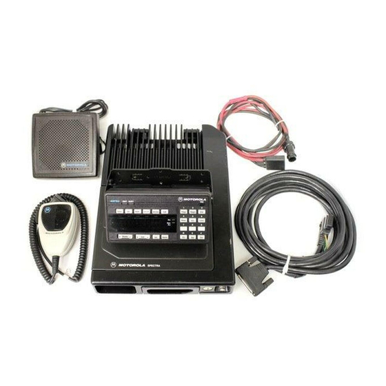
GPW-4141-A PICK UP FROM PAGE 9 Figure 3. Typical Systems 9000 Control Unit VI. CONTROL UNIT (Spectra 9000) transmitting. The BUSY indicator lights when the select- ed channel is busy. NOTE 5. Scan Indicators Spectra 9000 radios use the Systems 9000 Con- trol Unit. -
Page 33: Table 5 Mode Jumper Placement
5. Microprocessor (MPU) 1. General The MPU operates in mode 2 (expanded bus with The Spectra 9000 control unit has solid state micro- internal ROM active). Table 5 gives jumper placements processor circuitry that operates the standard and for different modes. The clock frequency is 4.9152 optional features built into the system. -
Page 34: Table 6 Eeprom Jumper Table
During this interval, the processor generates tickle 10. Vehicle-Interface Ports (VIP) pulses to periodically fire Q4, preventing the inverting- The VIP outputs are driven by a serial-to-parallel input voltage from rising above the non-inverting input shift register. Output transistors (Q28, Q29, Q30) can voltage and repeating the reset cycle. -
Page 35: Figure 4 Disassembly Of The Control Unit
processor to the display driver. When the clock line is CR116, CR117, and CR118 are connected to thermistor held low for more than 600 mSec, the display driver R163 by way of Q108. This circuit allows more current resets and new display data follows. to flow through these LEDs at room temperature and reduces current as the temperature rises. -
Page 36: Table 7 Vip Output Connections
For further informa- extreme caution when heating. Never reuse a chip tion on VIP outputs, see the control unit programming or SOT part; always replace with correct Motorola manual. parts. 2. VIP Input Connections 2. -
Page 37: Front Panel Programming And Adjustments
Scroll buttons are used on the rotary con- control head command. trol head for programming instead of the Vol rocker switch used on the other Spectra radio control heads. III. TOP-LEVEL MENU On rotary control heads, you must use the scroll but-... -
Page 38: Figure 5 Systems 9000 Control And Programming Control Controls
XMIT BUSY Mode Mode Select Home Down Volume Volume MAEPF-21456-A Down MAEPF-21456-A Figure 5. Spectra 9000 Control and Programming Control Controls POWER-UP ILLUSTRATOR DATE ENGINEER DATE MODE 02 RADIO 12-11-91 Illus AM/JP PRESS 5 TIMES (NORMAL EDITOR DATE CHECKER DATE... -
Page 39: Change Parameters Associated Witha Zone (See Figure 8.)
"SERVICE" "RADIO" "ZONE" "MODE" "ALIGN" "TST FREQ" "CH TEST" "EXIT" SELECT SELECT SELECT "SITE" ZONE "HOME SEL" "STATUS" "EXIT" NAME FREQ SIGNAL SELECT "EXIT" "PHONE" "MESSAGE" "SECURE" EXIT "SCAN" NAME MODE NAME "NAME" "CALL" "SCAN" "EXIT" "LO POWER" "REF OSC" "EXIT"... -
Page 40: Edit Zone Scan Lists
2. Press HOME to save the new zone name and VIII. CHANGE MODE NAMES (See Figure 10.) return to the "NAME" display. If you wish to change NOTE other zone names, press Mode to scroll through the Radio service software can be used to disable mode selections to "EXIT."... -
Page 41: Edit Selective-Call List
4. Press HOME to save the new mode name and If your radio has a 12-button keypad, you can delete return to the "NAME" display. If you wish to change the existing numbers with the Del button. Then, enter another mode name, press Mode to scroll to "EXIT" the last five digits of the ID number with the keypad. - Page 42 Not all radios have mode-slaved or personality- scroll through all the eligible modes. As you scroll slaved scan list capability, and some have the capability through the modes, the "PRI" and "N PRI" indicators on only certain modes. A scan list-capable mode can identify the modes that are on the list.
-
Page 43: Change Radio-Wide Parameters
on which they operate. Once HOME has been pressed XII. SELECT RADIO HOME MODE while the "SCAN" display is being shown, the display will One of the enabled modes in the radio is the “home” change to show the first eligible mode name. If the mode that you can access quickly by pressing the mode is already in the list, "N PRI"... -
Page 44: Change Status, Message, Site, Mpl, Or Single Tone Names
2. To Edit the Phone Number After pressing HOME to select a name, that name will display with the first character flashing. Press VOL Go through step 1, above, to advance the editor to and Mode to change one of these names just like you the phone number display. -
Page 45: Entering Password
3. Exit the RAC Menu: 3. Select “REF OSC” for front panel reference oscilla- tor frequency adjustment. After editing the repeater names and IDs, scroll through the repeater list by pressing Mode until "EXIT" 4. Select “DEV” for front panel transmitter deviation is shown on the display. -
Page 46: High-Power Adjustment
Connect the radio to the power meter and the Press Mode to scroll through the three test mode 50-ohm load, and be sure the radio supply voltage is frequencies (HI 1 XXX, HI 2 XXX, and HI 3 XXX) and 13.6 Vdc ±0.2 V. - Page 47 mode transmit frequency (see Table 9) to be used, and Press Mode to scroll through the three test mode “XX” represents the current transmit deviation setting in frequencies (DEV1 XX, DEV2 XX, and DEV3 XX) and radio memory. There is no direct correlation between adjust each as described above.
-
Page 48: Alignment Via Ibm Personal Computer
II. POWER SET AND CURRENT LIMIT ADJUSTMENT Using an IBM PC, interface hardware, and associat- ed software, field personnel can adjust the Spectra radio 1. Connect a power meter and a 50-ohm load (or ser- for either periodic alignment or advanced alignment vice monitor) to the antenna connector, using required when a damaged or failed board is replaced. -
Page 49: Table 10 Alignment Procedures
Table 10. Alignment Procedures Procedure > Reference Deviation Power Set & Compensation Compensation Signalling Memory Oscillator Adjustment Current Limit Adjustment Calibration Deviation Module ITEM Warping Adjustment Initialize RF BOARD First Third Second REFERENCE Only OSCILLATOR VCO BOARD Second First COMMAND BOARD Second Fifth Third... -
Page 50: Reference Oscillator Adjustment Procedure
III. REFERENCE OSCILLATOR ADJUSTMENT IV. TRANSMIT DEVIATION ALIGNMENT PROCEDURE PROCEDURE Adjustment of the reference oscillator is critical to NOTE radios operating in the 896 MHz band (which has much Compensation should not require any adjustments; tighter channel spacing than the other land mobile however, if for any reason such adjustments are bands). -
Page 51: Compensation Alignment Procedure
V. COMPENSATION ALIGNMENT PROCEDURE 9. Use the up and down arrow keys to adjust the com- pensation value until the deviation is within ±+0.2 Compensation alignment balances the modulation dB (2.3%) of the value noted in step (7). sensitivity of the VCO and reference modulation (syn- thesizer low-frequency port) lines. -
Page 52: Tx Compensation Calibration Alignment Procedure
VI. TX COMPENSATION CALIBRATION 12. Repeat step (11) until all four zones have been ALIGNMENT PROCEDURE adjusted. Alignment of compensation calibration points is a 13. Press F8 to program the value. way of correcting for deviation sensitivity vs RF frequen- 14. -
Page 53: Signalling Deviation Adjustment
If adjustment is required, insert a long tuning tool either conventional or trunked modes. On conven- (Motorola Part No. 66-84974L01) through the micro- tional radios without MDC or DTMF, these phone’s rear housing access hole, located to the right of adjustment procedures are not required. -
Page 54: Troubleshooting And Repair
TROUBLESHOOTING AND REPAIR POWER-UP SELF-CHECK DISPLAYS (Spectra and Spectra 9000 Control Head) When the radio is powered up, the control head goes through a self-test routine to check for system failures. Table 11 lists the error messages that may appear in the display, followed by the possible causes and remedies. -
Page 55: System Self-Check
Spectra Spectra 9000 DESCRIPTION OF PROBLEM FAIL 08/10 Option serial bus failure. See the Spectra 9000 siren/PA option instruction manual. II. SYSTEM SELF-CHECK In this case, the display indicates "ERROR__/__.” This specifies the error. When this display appears, the oper- When the radio system is turned on it displays ator is alerted by a beep. -
Page 56: Transmitter Troubleshooting
A. Display Messages III. TRANSMITTER TROUBLESHOOTING Failure messages, "FL XX/XX,” or error messages, When setting or measuring RF power at 900 MHz, "ER XX/XX,” are related to radio command board prob- you must follow these guidelines to avoid measurement lems in all cases except the following: errors due to cable losses or non-50-ohm connector VSWR: •... -
Page 57: Table 12 Transmitting Troubleshooting Chart
Table 12. Transmitting Troubleshooting Chart Symptom Possible Cause Correction or Test (Measurements Taken at Room Temperature) No RF power out TX power level Check TX power level programming (from front panel or programmer). programming No keyed 9.6V from Check for keyed 9.6V on pin 15 of J500 w/transmitter keyed. If none, replace command board command board. -
Page 58: Receiver Troubleshooting
This chart does not attempt to isolate output must never be grounded. Use an audio problems to the component level. isolation transformer (for example, Motorola Part No. SLN6435A) to isolate test equipment from the Audio PA (U450)/ speaker. - Page 59 (continued) Table 13. Receiver Troubleshooting Chart Symptom Possible Cause Correction or Test (Measurements Taken at Room Temperature) RF sensitivity poor Synthesizer not on Check synthesizer frequency; if off by more than 250Hz, go to synthesizer frequency/working troubleshooting chart. Antenna switch Check insertion loss from antenna connector to Rx front end coax from the PA;...
-
Page 60: Synthesizer Troubleshooting
(complementary metal oxide semiconductor) type. NOTE Because of their high open-circuit impedance, CMOS Wear a conductive wrist strap (Motorola part no. ICs are vulnerable to damage from static charges. RSX-4015A) to minimize the buildup of static Everyone involved in handling, shipping, and servicing... -
Page 61: Vii. Board Replacement
XMIT and Busy LED before removing the elas- remove and replace the printed circuit boards in the tomer keypad. Remove the elastomer keypad from Spectra radio. After troubleshooting and determining the printed circuit board. which board needs to be replaced, disconnect the test 4. -
Page 62: Figure 14 Control Head Assembly Screw Sequence
5. Remove the PC board from the internal spacer. CAUTION The PC board snaps into and out of the spacer. Take care to avoid misalignment of connec- tor pins. Remove the radio top cover and IMPORTANT NOTE command board cover (earlier models) to Early model radios used a flex cable to interconnect allow visual inspection during connector between the command board and the control head. -
Page 63: Figure 16 Pa Board Screw Fastening Sequence
Apply a new, uniform coat of ther- shield, and pull the other side of the clip. Unfold mal compound (for example, Motorola part no. the RF cables and remove the PA compartment 11-83166A01), which is thick enough to fill all shield. -
Page 64: Figure 17 Installing The Final Device
c. Solder three leads of Q9500 pass device. Install radio’s top and bottom covers. d. Install the PC board and attach and tighten the 5. Alignment screws in the sequence shown in Figure 16. Perform the "Power Set and Current Limit Adjust- e. -
Page 65: Board Replacement
6. When alignment is complete, press F10 to exit. 7. Apply a thin coat of thermal compound (for exam- 7. See Table 16 and perform the other alignment ple, Motorola part no. 11-83166A01) to the audio procedures indicated. final mounting surface. -
Page 66: Special Repair Procedure
Apply a thin coat of thermal compound (for exam- Ensure that the board and gasket are straight and ple, Motorola part no. 11-83166A01) to the power that the board does not bind as the screws are tight- module and voltage control pass device and final device ened, pulling the board down to the cavity ledge. -
Page 67: Table 15 Minimum Rf Performance Tests For Board Replacement
1. Before reassembly, apply a thin coat of thermal to securing the PC board mounting screws. This will compound (for example, Motorola part no. ensure proper thermal conduction. Both surfaces of the 11-83166A01) to the bottom of the audio PA insulator require thermal compound. -
Page 68: Test Frequency Menu
Table 16. Alignment Procedures Procedure > Reference Deviation Power Set & Compensation Compensation Signalling Memory Oscillator Adjustment Current Limit Adjustment Calibration Deviation Module ITEM Tuning Adjustment Initialize RF BOARD First Third Second REFERENCE Only OSCILLATOR VCO BOARD Second First COMMAND BOARD Second Fifth Third... -
Page 69: Control Head Testing
increments, not in the usual 16. This allows more pre- When in transmit mode, DTMF modulation pro- cise setting of rated audio, etc. Press HOME to move duces a sidetone in the speaker. All signalling types will the cursor back and forth between the frequency and continually modulate the transmitted signal for detec- signalling type. -
Page 70: Figure 19 Spectra Control Head Self-Test
Spectra control head; Figure 22 shows the control head, accessories and key number that should display for each key for the Spectra 9000 control head. -
Page 71: Figure 20 Spectra 9000 Control Head Self-Test
T33 - T43 & T83 FOR A4 - A5 - A7 - A9 RADIO FRONT OPTIONS CONNECTOR CONTROL HEAD CONNECTOR FOR A4 - A5 - A7 - A9 (Siren/PA Option or PA Option) MAEPF-21669-O MAEPF-21670-O RADIO T33 - T43 & T83 T33 - T43 &... -
Page 72: Figure 21 Front Panel Diagnostics; Key Closure Displays
KEY 02 KEY 30 KEY 32 KEY 34 KEY 42 KEY 01 KEY 31 KEY 33 KEY 41 KEY 43 KEY 45 Mode Phon Scan Call KEY 46 XMIT KEY 49 BUSY HOME KEY 48 KEY 08 KEY 44 KEY 47 KEY 40 MIC PTT: KEY 03 KEY 4A... -
Page 73: Figure 22 Front Panel Diagnostics; Key Closure Displays
INSERT GPW-7221-B Figure 22. Front Panel Diagnostics; Key Closure Displays... -
Page 74: Control Station Operation
CONTROL STATION OPERATION DESCRIPTION III. INSTALLATION AND OPERATION Option W665 allows a Spectra mobile radio to be NOTE used as a control station in a fixed location. This option Refer to the appropriate operator’s manual supplied includes the following items for use with the customer with the radio for operating information. - Page 75 INSERT GXW-4278-O PICKUP FROM PW-4320-O CONTROL STATION WIRING DIAGRAM...
- Page 76 GXW-4323-A FOLDING RIBBON CABLE FOR INSTALLATION GXW-4324-B INSTALLING RIBBON CABLE (12-WATT) GXW-4325-B FOLDING RIBBON CABLE (30-WATT) RIBBON CABLE INSTALLATION DETAILS...
- Page 77 PICKUP FROM GXW-4295-O & 4296-O HORN/LIGHTS WIRING DIAGRAM (Spectra Rear Accessory Connector) EMERGENCY SWITCH WIRING DIAGRAM (Spectra Rear Accessory Connector) WIRING DIAGRAM FOR HORN/LIGHTS AND EMERGENCY FEATURES FOR SPECTRA DASH-MOUNT RADIOS...
- Page 78 Spectra Mechanical Exploded View Parts List MXW-6224-C REFERENCE MOTOROLA SYMBOL PART NO. DESCRIPTION 2680010M02 heatsink, mid-power 0380102P01 screw, tapping, M3.5 x 0.60 x 10 2680009M02 heatsink, low-power (8 used) 2680105N01 shield, mid-power PA board 0380043L01 screw, metric, M3.0 x 10 (4 used)
- Page 79 INSERT GXW-6225-B PUSHBUTTON SPECTRA 900 MHz RADIO MECHANICAL EXPLODED VIEW...
- Page 80 Exploded View (Rotary Dash Mount) Control Head Parts List TPLF-3993-B ITEM MOTOROLA DESCRIPTION PART NO. 0380077M01 SCREW, Control Head Mounting (Qty 2) 3602113Z02 KNOB, Control Volume 3602113Z01 KNOB, Control Mode 0284218M01 NUT,Switch Volume 0284218M02 NUT,Switch Mode 0484219M01 LOCKWASHER, Switch Volume...
- Page 81 1580062P03 HOUSING, Remote Front SECURE 3280025R01 GASKET, Remote HLN6161B BOARD, Remote Interconnect 0400131974 WASHER, Flat (Qty 3) 0310945A11 SCREW, Tapping (Qty 3) 3280289L02 GASKET, Housing 1580005G01 COVER, Dust MECHANICAL EXPLODED VIEW AND PARTS LIST FOR SPECTRA ROTARY CONTROL HEAD...
- Page 82 HOUSING, Front Remote SECURE 3280025R01 GASKET, Remote HLN6161B BOARD, Remote Interconnect 0400131974 WASHER, Flat (Qty 3) 0310945A11 SCREW, Tapping (Qty 3) 3280289L02 GASKET, Housing 1580005G01 COVER, Dust MECHANICAL EXPLODED VIEW AND PARTS LIST FOR SPECTRA REMOTE MOUNT PUSHBUTTON CONTROL HEADS...
- Page 83 Spectra 9000 Control Unit Exploded View MXW-7318-C REFERENCE MOTOROLA SYMBOL PART NO. DESCRIPTION 1380087J01 escutcheon HLN5083A button, EMER HLN5091A button, DIR HLN5066A button, SCAN HLN5256A button, SRCH HLN5074A button, CALL HLN5268A button, PAGE HLN5259A button, RPGM HLN5258A button, SITE HLN5090A...
-
Page 84: Ak" Suffixed Models
MODEL CHART FOR SPECTRA 900 MHz CONVENTIONAL AND PRIVACY PLUS RADIOS “AK” SUFFIXED MODELS MODEL DESCRIPTION D27KGA5JBAK 12-Watt Standard, Privacy Plus D37KGA5JB5AK 30-Watt Standard, Privacy Plus D37KGA5JB7AK 30-Watt Expanded, Privacy Plus D37KGA5JB9AK 30-Watt Dual, Privacy Plus D37KMA7JA5AK 30-Watt Standard, Conventional... -
Page 85: Bk" Suffixed Models
MODEL CHART FOR SPECTRA 900 MHz CONVENTIONAL AND PRIVACY PLUS RADIOS “BK” SUFFIXED MODELS MODEL DESCRIPTION D27KGA5JB5BK 12-Watt Standard Privacy Plus D37KGA5JB5BK 30-Watt Standard Privacy Plus D37KGA5JB7BK 30-Watt Expanded Privacy Plus D37KGA5JB9BK 30-Watt Dual Privacy Plus D37KMA7JA5BK 30-Watt Standard Conventional... -
Page 86: Model Chart For Spectra 900 Mhz Privacy Plus Radios "Ck" Suffixed Models
MODEL CHART FOR SPECTRA 900 MHz PRIVACY PLUS RADIOS “CK” SUFFIXED MODELS MODEL DESCRIPTION D27KGA5JB5CK 12-Watt Standard Privacy Plus D37KGA5JB5CK 30-Watt Standard Privacy Plus D37KGA5JB7CK 30-Watt Expanded Privacy Plus D37KGA5JB9CK 30-Watt Dual Privacy Plus ITEM DESCRIPTION • • • •... -
Page 87: Ck" And "Dk" Suffixed Models
MODEL CHART FOR SPECTRA 900 MHz CONVENTIONAL AND PRIVACY PLUS RADIOS “CK” AND “DK” SUFFIXED MODELS MODEL DESCRIPTION D27KGA5JB2AK 12-Watt Limited Privacy Plus D27KGA5JB5DK 12-Watt Standard Privacy Plus D37KGA5JB5DK 30-Watt Standard Privacy Plus D37KGA5JB7DK 30-Watt Expanded Privacy Plus D37KGA5JB9DK 30-Watt Dual Privacy Plus... -
Page 88: Ek" Suffixed 12 * 30-Watts Models
MODEL CHART FOR SPECTRA 900 MHz PRIVACY PLUS RADIOS “AK” SUFFIXED 4-WATT MODELS “EK” SUFFIXED 12 & 30-WATTS MODELS MODEL DESCRIPTION D17KGA5JB7AK 4-Watt Expanded Privacy Plus D27KGA5JB2BK 12-Watt Standard Privacy Plus D27KGA5JB5EK 12-Watt Standard Privacy Plus D27KGA5JB7AK 12-Watt Expanded Privacy Plus... -
Page 89: Ck" Suffixed 12 & 30-Watts Models
MODEL CHART FOR SPECTRA 900 MHz SMARTNET RADIOS “AK” SUFFIXED 4-WATT MODELS “CK” SUFFIXED 12 & 30-WATTS MODELS MODEL DESCRIPTION D17KGA5JC7AK 4-Watt Dual SMARTNET Expanded D27KGA5JC2CK 12-Watt Dual SMARTNET Limited D37KGA5JC5CK 30-Watt Dual SMARTNET Standard D27KGA5JC5CK 12-Watt Dual SMARTNET Standard... -
Page 90: Bk" Suffixed Models
MODEL CHART FOR SPECTRA 900 MHz SMARTNET RADIOS 12 & 30-WATTS RF POWER “BK” SUFFIXED MODELS MODEL DESCRIPTION D27KGA5JC2BK 12-Watt Dual SMARTNET Limited D27KGA5JC5BK 12-Watt Dual SMARTNET Standard D27KGA5JC7BK 30-Watt Dual SMARTNET Expanded D37KGA5JC5BK 30-Watt Dual SMARTNET Limited ITEM DESCRIPTION •... -
Page 91: Feature Matrix For Spectra 900 Mhz Conventional Radios "Ak", "Bk", "Ck" Suffixed Models
FEATURE MATRIX FOR SPECTRA 900 MHz CONVENTIONAL RADIOS “AK” , “BK”, “CK” SUFFIXED MODELS MODEL A5 Package A7 Package • STANDARD FEATURES: ( ) OPTION: ( • • 8-Character Alphanumeric Display • • Power-Up Self-Check • • Full Mil 810D Specifications •... -
Page 92: Feature Matrix For Spectra 900 Mhz Privacy Plus Radios "Ak" And "Ck" Suffixed Models
FEATURE MATRIX FOR SPECTRA 900 MHz PRIVACY PLUS RADIOS “AK” AND “CK” SUFFIXED MODELS MODEL B2 Package (“AK” Suffixed Model Only) B5 Package B7 Package B9 Package • STANDARD FEATURES: ( ) OPTION: ( • • • • 8-Character Alphanumeric Display •... -
Page 93: Feature Matrix For Spectra 900 Mhz Privacy Plus Radios "Ck" And "Dk" Suffixed Models
FEATURE MATRIX FOR SPECTRA 900 MHz PRIVACY PLUS RADIOS “CK” AND “DK” SUFFIXED MODELS MODEL B5 Package B7 Package B9 Package • STANDARD FEATURES: ( ) OPTION: ( • • • 8-Character Alphanumeric Display • • • Power-Up Self-Check • • •... -
Page 94: Feature Matrix For Spectra 900 Mhz Smartnet Radios "Ak", "Bk", "Ck" Suffixed Models
FEATURE MATRIX FOR SPECTRA 900 MHz SMARTNET RADIOS “AK”, “BK”, “CK” SUFFIXED MODELS MODEL C2 Package C5 Package C7 Package • STANDARD FEATURES: ( ) OPTION: ( • • • 8-Character Alphanumeric Display • • • Power-Up Self-Check • • •... -
Page 95: Feature Matrix For Spectra 900 Mhz Privacy Plus Radios "Ek" Suffixed Models
FEATURE MATRIX FOR SPECTRA 900 MHz PRIVACY PLUS RADIOS “EK” SUFFIXED MODELS MODEL B2 Package (“BK” Suffixed Model Only) B5 Package B7 Package B9 Package • STANDARD FEATURES: ( ) OPTION: ( • • • • 8-Character Alphanumeric Display • • • •... - Page 96 MECHANICAL EXPLODED VIEW PARTS LIST FOR SPECTRA 900 MHz RADIO...