Panasonic Panaboard UB-5315 Operating Instructions Manual
Electronic board
Hide thumbs
Also See for Panaboard UB-5315:
- Operating instructions manual (56 pages) ,
- Installation manual (20 pages) ,
- Specification sheet (4 pages)
Table of Contents
Advertisement
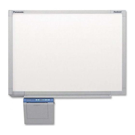
[Stand (option)]
The unit in this picture is UB-5315 series.
(Stand kit is optional.)
• To assemble this unit, please refer to the Installation Manual.
• Before operating this unit, please read these instructions completely and keep them carefully for future reference.
• Because of the nature of the print film, all the printed text will remain on the film.
[Wall-mounting]
Electronic Board
Operating Instructions
Model No.
English . . . . . . . . . . . . . . . . . .1–36
Français . . . . . . . . . . . . . . . .37–72
Deutsch . . . . . . . . . . . . . . .73–108
Español . . . . . . . . . . . . . .109–144
Italiano . . . . . . . . . . . . . . .145–180
Nederlands . . . . . . . . . . .181–216
Svenska . . . . . . . . . . . . . .217–252
中 文 . . . . . . . . . . . . . . . .253–288
Русский . . . . . . . . . . . . . .289–324
UB-5315
UB-5815
Advertisement
Table of Contents

Related Manuals for Panasonic Panaboard UB-5315


Summary of Contents for Panasonic Panaboard UB-5315
-
Page 1: Operating Instructions
[Stand (option)] [Wall-mounting] The unit in this picture is UB-5315 series. (Stand kit is optional.) • To assemble this unit, please refer to the Installation Manual. • Before operating this unit, please read these instructions completely and keep them carefully for future reference. - Page 2 Thank you for purchasing the Panasonic Electronic Board. For optimum performance and safety, please read these instructions carefully. Model number: _________________________ Serial number: _________________________ Dealer’s address: ______________________________________________________________________ • Thermal transfer film ....1 •...
-
Page 3: Table Of Contents
Table of Contents For Your Safety ........4 Before Precautions . -
Page 4: For Your Safety
A replacement fuse cover can be purchased from your local Panasonic Dealer. If the fitted moulded plug is unsuitable for the socket outlet in your home then the fuse should be removed and the plug cut off and disposed of safely. -
Page 5: Precautions
Precautions Never remove the cover, take apart or modify the product. This will void the warranty. Do not put drinks, other liquids or heavy items on the tray or screen. Do not use the electronic board in an excessively humid or dusty location. Do not position the electronic board in a location where it is unstable. -
Page 6: Cd-Rom
Precautions Do not lean against the screen or on the cover (lower), even if the electronic board is mounted on the wall. Confirm both sides of the screen are hung in the same height slots. Slot 3 Slot 2 Slot 1 ■... - Page 7 Installation • Do not install the unit where it may be exposed to direct sunlight, near heating equipment, or near air-conditioning vents as this may cause stretching and/or discoloration of the screen. • Do not install the unit in strong sunlight or strong lighting. Proper copying may become impossible.
-
Page 8: Part Names And Functions
Part Names and Functions Scanner Stand The stand is optional. Output Port This port holds up to 10 sheets of output paper. Printer Open Lever Push down this lever to open the printer door. USB Connector (See page 22.) Paper Cover Printer Door Open this cover to Open this door to load a... -
Page 9: Control Panel
■ Control panel Contrast/Remaining Film Indicator Contrast Key 2-Screen Copy Key Panel Name Contrast/ Remaining Film Indicator Contrast 2-Screen Copy Key Multi-Copy/ Error Indicator Multi-Copy/ Stop Key Copy Key Advance Advance Key Copy Key Description This lamp indicator notifies the user when the time to replace the thermal transfer film is approaching (estimated) and of the printing contrast used during copying. -
Page 10: Installing The Thermal Transfer Film
Installing the Thermal Transfer Film Install the thermal transfer film in the printer. Printer door Set the power switch to on ( I ). • “ ” will flash on the Multi-Copy/Error Indicator when the thermal transfer film has run out. Push down the printer open lever and open the printer door. - Page 11 Blue gear White shaft Blue gear Latches Installing the Thermal Transfer Film 3) Place the blue gear on the front right groove. 4) Place the white shaft on both sides of the back grooves. Tighten the film, then close the printer door. 1) Rotate the blue gear in the direction of the arrow to take up the slack on the film.
-
Page 12: Loading Copy Paper
Loading Copy Paper It is possible to load up to 40 sheets of A4 (Letter*) size copy paper (assuming a paper weight of 80 g/m Note that only A4 (Letter*) size paper may be used. When the unit is first used or when “ paper, load copy paper as described below. - Page 13 Guide Maximum paper limit Loading Copy Paper To prevent paper jams such as those caused by multiple sheets feeding at once, fan the paper thoroughly, square it, align it with the guide inside, and insert as far as it will go. Notes •...
-
Page 14: Making Copies
Making Copies This section describes how to copy text and illustrations drawn on the screen. Set the power switch to on ( I ). • “ ” will light on the Multi-Copy/Error Indicator to indicate that the unit is ready to copy. Press the Copy Key •... -
Page 15: Copy Types And Procedures
■ Copy types and procedures Copy Type Copying the front of Press the screen Copying the back of the screen Making multiple copies (up to 9) Making 2-screen Press copies • Copying the front and back of the screen on a single sheet of paper Copying chart Chart paper can be attached to the screen as shown in the figure... -
Page 16: Replacing The Thermal Transfer Film
Thermal transfer film is replaced as follows. Notes on Replacing Thermal Transfer Film • Only use the designated product (UG-6001) from Panasonic as the replacement film. (Note that using another type of replacement film may result in degraded printing quality or damage to the unit.) •... -
Page 17: Paper Jams
Paper Jams Remove paper jams by the following procedure when copy paper does not come out of the output port or when “ flashes on the Multi-Copy/Error Indicator. Jammed paper Push down the printer open lever to open the printer door. Remove the thermal transfer film with both hands. - Page 18 Paper Jams If the flashing “ ” does not go out after the foregoing procedure has been performed; this may indicate that the paper feeder is not functioning properly. Reload the copy paper by following the steps given below. Install the thermal transfer film. •...
- Page 19 Guide Maximum paper limit To prevent paper jams such as those caused by multiple sheets feeding at once, fan the paper thoroughly, square it, align it with the guide inside, and insert as far as it will go. Note • Do not stack more copy paper in the unit than the maximum paper limit indicated by the guide (see figure to the left) as this may result in paper jams.
-
Page 20: Screen Height Adjustment
Screen Height Adjustment The screen can be adjusted at 3 levels except for the lowest level. The lowest level of the board attachment frame is designed for installation of the screen, so the printer cannot be attached at this level. Adjust the level of the screen unit as follows. - Page 21 Height adjustment handles Step frame Board attachment (upper) Screen Height Adjustment Tighten the height adjustment handles. Height Be sure to tighten the height adjustment handles adjustment handles firmly after adjusting the level of the screen. Keep the step frame by hanging it on the board attachment (upper).
-
Page 22: Computer Interfacing
* If you connect the electronic board to a USB hub, it is not guaranteed to work. * Please note that if more than one Panasonic electronic boards are connected in a USB tree, only one of those electronic boards will perform the computer interfacing. -
Page 23: Installing The Driver And Software
■ Installing the driver and software Installing the USB and Printer driver Windows 98 Power on your computer and start Windows. Power on the electronic board, and connect the unit and your computer with a USB cable. When “USB Composite Device” is detected, click the [Next] button. - Page 24 Computer Interfacing Windows Me Power on your computer and start Windows. Power on the electronic board, and connect the unit and your computer with a USB cable. When “Panaboard-UB5 USB Device” is detected, click on the “Specify the location of the driver (Advanced)” check button and click the [Next] button.
- Page 25 Note Special Note for Windows 98/Me If your computer had Windows 98/Me pre-installed and the original Windows 98/Me CD-ROM or diskettes were not included. In this situation, please try to locate the necessary files by following the methods described below or refer to your computer’s User’s Guide for more details.
- Page 26 Computer Interfacing Windows 2000 Power on your computer and start Windows. • Log on as an administrator. Power on the electronic board, and connect the unit and your computer with a USB cable. When “Welcome to the Found New Hardware Wizard” dialog box appears, click the [Next] button.
- Page 27 When the installation of “Panaboard- UB5 USB Device Driver” is completed, click the [Finish] button. Computer Interfacing When “Panasonic Panaboard-UB5 USB Printer (A4/Letter)*” is detected, click on the “Install from a list or specific location (Advanced)” check button and click the [Next] button.
- Page 28 Computer Interfacing Installing Panasonic-DMS software and TWAIN driver When an old version of Panasonic-DMS is already installed, remove it and install the new version of the software in the same folder. Power on your computer and start Windows. • Log on as an administrator for Windows 2000 or Windows XP.
-
Page 29: Removing The Driver And Software
■ Removing the driver and software Removing Panasonic-DMS software and TWAIN driver If you need to remove the Panasonic-DMS software and TWAIN driver, perform the following steps. Power on your computer and start Windows. • Log on as an administrator for Windows 2000 or Windows XP. -
Page 30: Panaboard Operation Panel
Computer Interfacing ■ Panaboard Operation Panel It is possible to perform the same operations as with the electronic board control panel (page 9) from the following Panaboard Operation buttons. Note: While the Panaboard Operation Panel is displayed, the Copy Key and 2-Screen Copy Key on the electronic board control panel are used for scanning images into the computer. -
Page 31: Printing
Status Box The status box displays the status of the TWAIN driver and the electronic board. Stand by: The electronic board is stand by. Both of the Panaboard Operation Panel and the electronic board control panel are operational. Rotating: The electronic board is rotating the screen. -
Page 32: Daily Care And Maintenance
Daily Care and Maintenance Always turn off the power switch and unplug the power plug when cleaning outside and inside the unit. ■ Cleaning the screen and the unit ■ Caring for the eraser ■ Cleaning the printer head, platen roller and pick-up roller If black streaks appear on the copy, clean the printer head and the platen roller. - Page 33 Cotton swab Printer head (Gold) Pick-up roller Latches Daily Care and Maintenance Clean the Printer Head Dampen the tip of a cotton swab in ethyl alcohol and gently wipe the printer head. Note • Never touch the printer head or the surrounding area with your hands as this may disable copying.
-
Page 34: Help Troubleshooting
Troubleshooting Treat problems according to the information given in the table below. If problems still persist, call your dealer for service. Symptom Power switch is on but the indicator is off. Copied copy paper will not come out. Nothing is printed on the paper or copies are faint or blurred. -
Page 35: Meanings Of Error Codes
■ Meanings of error codes The following table describes the meaning of each of the symbols which may flash in the Multi-Copy/Error Indicator. Indication Data transfer error (Error) The screen will not move. (Screen) The printer door is not closed securely. -
Page 36: Specifications
Marker and eraser set: KX-B035 (contains one black, one red, and one blue markers and Letter size is for U.S.A. and Canada models. UB-5315 Refer to the name plate on the printer Refer to the name plate on the printer 1334 mm ×...