Advertisement
Quick Links
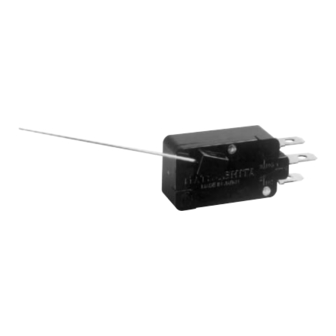
The AHR5 switch with actuating
lever and retainer assembled
CONSTRUCTION
Rotating
shaft
Handle
Pin
plunger
Restoration
spring
Stationary
contact
PRODUCT TYPES
Type
Retainer mounting direction
Standard (Silver alloy)
Low-level circuit type
(Gold clad)
Actuator lever
Remarks: 1. The retainer is provided with the switch body without assembled.
2. Actuating levers are available separately.
(AHR5801, length: 52.3mm 2.059inch)
3. As for International standard, please refer to the "Information".
SPECIFICATIONS
1. Contact rating (Resistive load)
Type
Standard (Silver alloy)
Low-level circuit type (Gold clad)
HIGH CONTACT PRESSURE
WITH LIGHT OPERATING
ACTION
FEATURES
• High contact pressure with light oper-
ating action
• Easy installation of the lever—Tools
or adhesives are unnecessary for at-
taching the actuating lever
• Low-level circuit type is also available
Actuating spring
Movable contact
Operating spring
Operating force (max.)
Counter-clockwise
Clockwise
0.1N•cm {10.2gf•cm}
Counter-clockwise
Clockwise
52.3mm
2.059inch
Solder and
Q.C. (187)
N.O. terminal
Common
terminal
N.C. terminal
Release force (min.)
0.013N•cm {1.3gf•cm}
—
Standard rating
5A 250V AC
1A 250V AC
11/2002
V-ROTARY
ACTION (AHR5)
SWITCHES
TYPICAL
APPLICATIONS
• Vending machines
SPDT .187 Quick-connect/
solder terminal
AHR5401
AHR5411
AHR540161
AHR541161
AHR5801
Low-level rating
6V DC 5mA
12V DC 2mA
24V DC 1mA
AHR5
75
Advertisement

Summary of Contents for Panasonic AHR5
-
Page 1: Typical Applications
(Gold clad) Clockwise Actuator lever 52.3mm 2.059inch Remarks: 1. The retainer is provided with the switch body without assembled. 2. Actuating levers are available separately. (AHR5801, length: 52.3mm 2.059inch) 3. As for International standard, please refer to the “Information”. SPECIFICATIONS 1. - Page 2 AHR5 2. Characteristics Type Mechanical (at O.T. rated) Expected life (min. operations) Electrical (at O.T. max.) Insulation resistance Between terminals Between terminals and Dielectric strength other exposed metal parts Between terminals and ground Contact resistance (initial) Vibration resistance (pin plunger)
- Page 3 = .028±.001 DIA. .020R 90° 4. Regarding switch mounting Mount the switch to a smooth surface us- ing M3 screws. Tighten the screw with 3 to 5 kg-cm torque. To prevent loosening of the mounting screws, it is recommended...